
A PL259 antenna system can work perfectly on a radio bench and still create problems when it is connected to a compact RF device. The reason is usually not the adapter itself. The failure often starts with a mismatch between connector direction, cable size, impedance, or the mechanical load placed on the smaller SMA interface.
This situation appears frequently when a traditional amateur radio antenna setup needs to connect with newer equipment such as SDR receivers, RF evaluation boards, wireless modules, or compact test devices. A PL259 to SMA adapter provides the physical transition, but the adapter only solves the interface problem. It does not correct an unsuitable antenna, wrong cable impedance, or excessive RF loss.
Before ordering an adapter, engineers and buyers usually need to answer several practical questions:
- Is the radio side PL259 or SO239?
- Does the SMA side need male, female, or reverse polarity?
- Is the system based on 50Ω coax?
These details determine whether a simple adapter is suitable or whether an adapter cable assembly is the safer choice.
How Does a PL259 to SMA Adapter Bridge Radio and RF Module Interfaces?
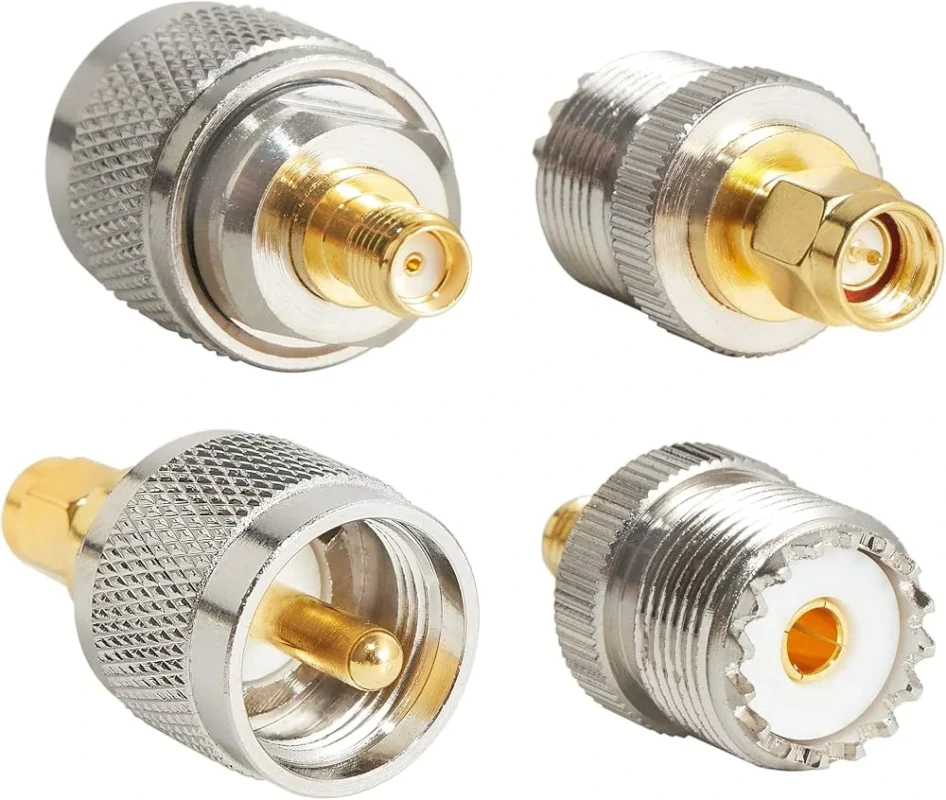
PL259 and SMA connectors were developed for different application environments. They can be connected together, but they usually appear in different parts of an RF system.
A PL259 connector is commonly found in traditional radio equipment. It is associated with the UHF connector family and is widely used in amateur radio stations, antenna tuners, HF transceivers, and coaxial antenna cables.
A connector that physically mates does not automatically guarantee good RF performance.
Explain why PL259 and SMA connectors appear in different RF systems
The reason these connectors often need conversion is simple: older radio equipment and newer RF electronics were designed around different priorities.
SMA systems usually prioritize:
- compact size
- higher-frequency operation
- PCB integration
- laboratory measurement compatibility
A small SDR receiver may only have an SMA input, while the antenna cable available from a radio installation may already be terminated with PL259. In this situation, a PL259 to SMA adapter becomes a practical bridge.
The adapter itself is simple, but the selection details are not.
Understand why adapter selection requires both connector and system matching
Many purchasing mistakes happen because buyers only check the connector names.
A request such as:
“Need UHF to SMA adapter”
is not enough information for production or sourcing.
The supplier still needs to know:
| Item | Required Confirmation |
| Radio-side interface | PL259 plug or SO239 socket |
| SMA-side interface | SMA male or SMA female |
| Polarity | Standard SMA or RP-SMA |
| Impedance | Usually 50Ω for RF systems |
| Cable connection | Existing cable type and diameter |
| Application | Antenna, SDR, testing, or production |
| Environment | Indoor, outdoor, vibration, repeated mating |
Two adapters may look almost identical but have different center contact structures. A wrong SMA polarity can result in a connector that appears compatible but cannot electrically connect.
This is especially common when replacing parts sourced from online listings where “SMA” is used as a general description.
Avoid using adapters to solve unrelated RF problems
A PL259 to SMA adapter can solve one problem:
Different connector interfaces.
It cannot solve:
- antenna tuning problems
- incorrect cable impedance
- excessive coaxial cable loss
- poor grounding
- damaged connectors
- incorrect operating frequency selection
For example, if an antenna system has a high SWR before the adapter is installed, adding an adapter will not remove the mismatch. The adapter only becomes another component inside the RF path.
The same applies to signal loss. A weak SDR signal may be caused by:
- long coax cable length
- unsuitable cable type
- poor shielding
- multiple adapter connections
not simply because a PL259 to SMA conversion exists.
How Do PL259, SO239, and SMA Interfaces Work Together?
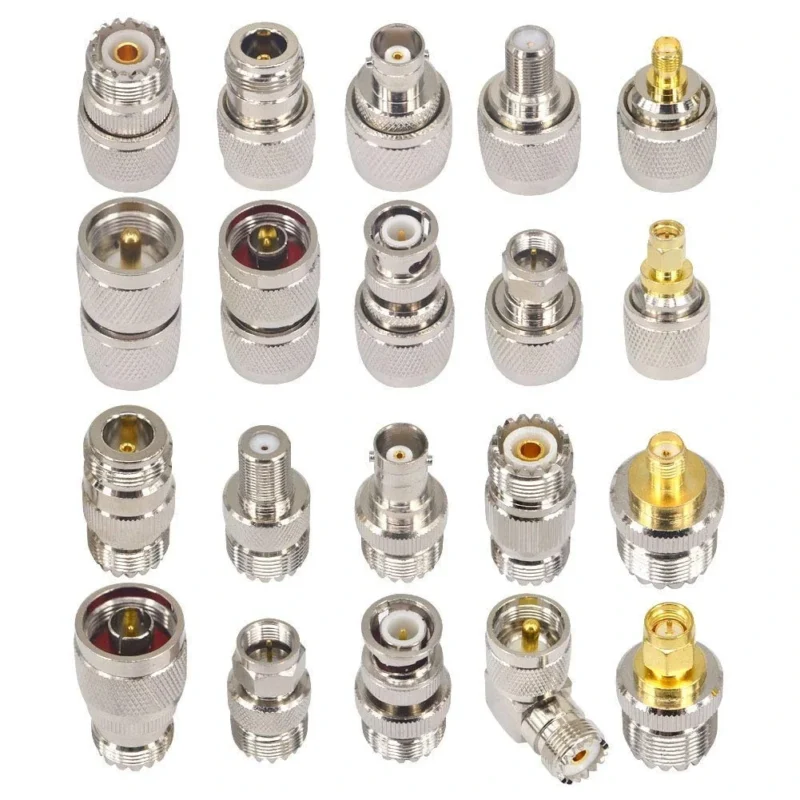
Before selecting an adapter, it is necessary to understand the relationship between PL259 and SO239.
The terms are often mixed together because both belong to the UHF connector family.
A simple rule:
- PL259 = plug side
- SO239 = socket side
A radio antenna cable commonly uses a PL259 plug, while a radio chassis or antenna tuner may provide an SO239 socket.
The adapter selection changes depending on which side is available.
For example:
- PL259 cable → SMA device → use a PL259 to SMA adapter
- SO239 equipment port → SMA cable → use an SO239 to SMA adapter solution
Using the wrong terminology during purchasing can result in receiving an adapter with the wrong mechanical interface.
Identify the relationship between PL259 and SO239 before choosing an adapter
A common mistake is assuming “UHF connector” means one fixed connector type.
In practice:
| Interface | Typical Role | Common Location |
| PL259 | Male cable connector | Antenna coax cable |
| SO239 | Female chassis connector | Radio equipment panel |
| SMA | Compact RF interface | SDR, RF module, test equipment |
The word “UHF” can also be confusing because it does not indicate modern ultra-high-frequency performance. It is a historical connector family name rather than a guarantee of RF capability.
For antenna systems, the complete RF path matters more than the connector label alone.
Compare traditional radio connectors with compact SMA interfaces
Different connectors exist because different systems have different mechanical and electrical requirements.
| Interface | Typical Application | Main Consideration |
| PL259/SO239 | Amateur radio antenna systems | Larger cable compatibility |
| SMA | RF modules, SDR, test equipment | Compact size and RF precision |
| BNC | Test equipment and instruments | Quick locking connection |
| N Type | Outdoor and communication systems | Environmental durability |
A PL259 to SMA adapter is therefore not replacing one connector with another. It is connecting two different equipment generations.
For a short bench test, the adapter may be the simplest solution.
For a permanent installation, especially with heavy coaxial cable, the mechanical design of the connection should be reviewed before final selection.
How Do You Choose the Correct PL259 to SMA Adapter Direction?
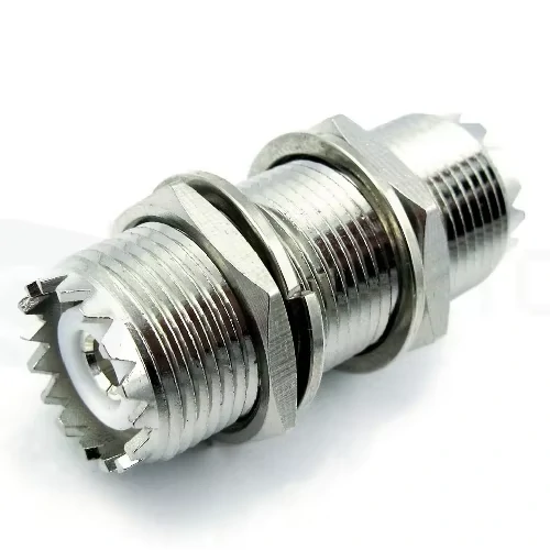
A right-angle PL259 to SMA adapter designed for connecting different RF connector standards. The angled structure helps reduce cable bending stress and improves installation flexibility in limited spaces.
The connector direction is one of the easiest details to overlook when purchasing an RF adapter. Many product listings use similar names, but the actual connection path may be completely different.
A PL259 to SMA adapter and an SMA to PL259 adapter describe the same connector family conversion, but the wording usually follows the signal path or the equipment side being connected.
For procurement, it is better to describe the two interfaces directly rather than relying only on the product name.
For example:
PL259 male to SMA female adapter, 50Ω, used to connect a radio antenna cable to an SDR receiver.
This description provides enough information for production because it identifies:
- PL259 side
- SMA side
- connector gender
- impedance
- application
Match PL259 cable side with SMA device side
In this case, the adapter must provide:
- PL259 female interface to accept the cable plug
- SMA interface matching the SDR device
The exact gender depends on the actual equipment interfaces. The adapter name alone does not always tell the complete mechanical configuration.
A practical sourcing method is to ignore the product title first and check the drawings or specifications.
Confirm:
- Thread type
- Center pin/socket structure
- Connector gender
- Mounting direction
- Cable clearance
This prevents a common mistake: receiving a physically similar adapter that cannot mate with the intended equipment.
Select SMA to PL259 adapters when the conversion direction is reversed
The phrase SMA to PL259 adapter is often used when the SMA device side is considered the starting point.
The RF conversion is the same, but the mechanical requirement may be different.
This matters when:
- connecting an SMA test port to a radio antenna
- building temporary measurement setups
- adapting laboratory equipment to field antennas
A buyer should specify the connection order clearly.
A better purchasing description:
SMA male to PL259 female adapter, 50Ω, for connecting RF test equipment to PL259 antenna cable.
is much clearer than:SMA UHF adapter
Avoid confusing SMA male, SMA female, and RP-SMA versions
SMA polarity is another frequent source of errors.
Standard SMA and RP-SMA connectors may look almost identical from the outside, but their center contact arrangement is different.
Standard SMA:
- SMA male usually has a center pin
- SMA female usually has a socket contact
RP-SMA:
- the center pin/socket arrangement is reversed
This difference is especially important for:
- Wi-Fi equipment
- wireless modules
- consumer RF devices
- antenna accessories
A PL259 to SMA adapter purchased with the wrong SMA polarity may screw onto the equipment correctly but fail electrically.
Before ordering, check:
| Check Item | Why It Matters |
| SMA standard or RP-SMA | Prevents incorrect center contact |
| Male/female interface | Ensures mechanical mating |
| Thread specification | Prevents incompatible connection |
| Device port drawing | Confirms actual interface |
How Does 50Ω Matching Affect PL259 to SMA Adapter Selection?
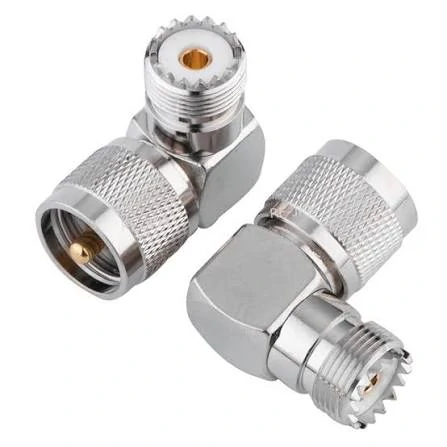
Internal structure and mechanical design of a PL259 to SMA RF adapter. A proper 50Ω impedance match is important for reducing signal reflection and maintaining stable RF performance in antenna and communication systems.
A connector conversion may look simple, but the RF path still needs to maintain the correct electrical environment.
Most amateur radio and RF module applications use a 50Ω system.
should maintain the same impedance throughout the connection.
If different impedance components are mixed, problems may appear as:
- higher SWR
- increased reflection
- signal reduction
- unstable measurement results
The adapter is only one part of the RF chain.
Keep radio antenna systems within the same impedance path
A common misunderstanding is that all coaxial adapters are interchangeable because they use similar threads.
They are not.
For example:
- 50Ω PL259/SMA adapter → suitable for many RF communication applications
- 75Ω coax accessories → commonly used in video or cable TV systems
The connector may physically connect, but the electrical design is different.
For antenna and SDR applications, buyers should confirm:
- system impedance
- cable impedance
- equipment specification
- operating frequency
before selecting the adapter.
Check cable type before selecting an adapter
The cable connected to the adapter affects both RF performance and mechanical reliability.
This is especially important when converting to SMA.
SMA connectors are compact and commonly mounted on smaller equipment. They are not designed to carry the mechanical load of a heavy outdoor coax cable hanging directly from the port.
Avoid mixing RF SMA adapters with unrelated coax accessories
A frequent field problem happens when an adapter is selected only by appearance.
The connection may look correct:
- threads match
- connectors tighten
- continuity test passes
but the RF result is poor.
Possible causes include:
- incorrect impedance
- unsuitable frequency range
- poor contact pressure
- damaged plating
- excessive adapter stacking
For low-frequency amateur radio use, a basic adapter may perform well.
When Should You Use a PL259 to SMA Adapter Instead of a Cable Assembly?
A common example is an existing antenna cable with a PL259 connector being connected to an SDR receiver, where the input interface is SMA.
For temporary testing, this solution is usually practical.
However, many RF connection problems appear after the first successful connection. The adapter works on the bench, but the final installation introduces new variables:
- cable weight
- bending force
- repeated mating
- outdoor exposure
- frequency requirements
The selection between an adapter and a cable assembly depends on how the connection will actually be used.
Use an Adapter When the Connection Needs Frequent Changes
A PL259 to SMA adapter is suitable for situations where flexibility is more valuable than permanent installation.
Typical applications include:
- SDR testing
- antenna comparison
- RF prototype development
- equipment troubleshooting
- temporary measurement setups
For example, an engineer may already have several antenna cables installed with PL259 connectors.
Replacing all existing cables is unnecessary. An adapter provides a faster way to connect different equipment.
The limitation is that the adapter becomes another component in the RF chain.
Every additional connection should be considered during troubleshooting because it introduces another possible point for:
- contact problems
- mechanical looseness
- impedance variation
- signal loss
For experimental setups, this trade-off is usually acceptable.
Choose a Cable Assembly When the Installation Will Stay in Place
A direct adapter connection is not always suitable for permanent applications.
The main concern is mechanical stress.
PL259 connectors are commonly used with larger coaxial cables. Some antenna cables are relatively heavy, especially outdoor cables designed for low loss.
SMA connectors are much smaller and are often mounted directly on compact equipment.
When a heavy cable hangs from an SMA port, the connector may experience continuous force.
The cable takes the mechanical load, while the SMA interface only performs the RF connection.
Avoid Using Too Many RF Adapter Conversions
One adapter is usually easy to manage.
Several adapters connected together create more uncertainty.
may still function, but every additional transition adds:
- another contact interface
- another mechanical joint
- another possible mismatch point
For low-frequency applications, the effect may be small.
For RF testing or systems operating closer to the upper frequency range, reducing unnecessary conversions is usually better.
A shorter RF path is easier to test and maintain.
Adapter or Cable Assembly? Practical Selection Reference
| Usage Condition | Recommended Choice | Reason |
| Temporary RF experiment | Adapter | Easy installation and removal |
| SDR receiver testing | Adapter | Flexible equipment switching |
| Heavy antenna cable | Cable assembly | Reduces SMA mechanical stress |
| Outdoor fixed installation | Cable assembly | Better long-term stability |
| Production testing | Cable assembly | Better repeatability |
| Occasional troubleshooting | Adapter | Faster replacement |
The important question is not simply whether two connectors can mate.
The better question is whether the connection remains stable after installation.
How Do PL259 to SMA Adapters Compare With Other RF Conversions?
PL259 to SMA is only one option in RF interface conversion.
Compare PL259 Conversion With SO239 to SMA Solutions
SO239 is the socket counterpart commonly paired with PL259.
If the equipment side provides an SO239 socket, the required adapter is different from a cable-side PL259 conversion.
How Can You Check a PL259 to SMA Adapter Before Installation?
A basic visual inspection should be completed before connecting the adapter into an RF system.
Check:
- connector threads
- center contact condition
- plating surface
- insulation material
- mechanical damage
A connector can look normal but still have contact problems.
Perform Basic Electrical Inspection
For incoming inspection or production use, basic tests include:
| Inspection Item | Purpose |
| Center continuity | Confirm signal path |
| Shield continuity | Confirm grounding |
| Insulation resistance | Detect unwanted connection |
These checks are useful, but they cannot replace RF testing.
A continuity result only confirms the electrical path exists.
It does not confirm:
- VSWR
- return loss
- insertion loss
Test RF Performance When Needed
For applications with higher RF requirements, additional measurement may include:
- VSWR test
- return loss measurement
- insertion loss measurement
A VNA test is commonly used when:
- the operating frequency is high
- the adapter is used in test equipment
- multiple RF transitions exist
- production consistency matters
PL259 to SMA Adapter Inspection Checklist
| Parameter | Confirmation |
| Conversion direction | PL259 to SMA / SMA to PL259 |
| PL259 interface | Plug or SO239 side |
| SMA interface | Male / Female / RP-SMA |
| Impedance | 50Ω |
| Cable compatibility | RG / LMR series |
| Frequency requirement | Confirm operating band |
| Mechanical condition | Pass / Fail |
| RF test requirement | VSWR / return loss if required |
This type of checklist is useful when preparing RF purchasing specifications.
How Should Buyers Request a PL259 to SMA Adapter?
Many sourcing mistakes happen because the request contains only connector names.Need UHF to SMA adapterThis description is incomplete.
FAQ
Is PL259 the same as a UHF connector?
PL259 is commonly used as the plug type within the UHF connector family. The matching socket is usually SO239.
The term “UHF connector” can be confusing because it does not indicate the actual operating frequency capability of the connector.
Will a PL259 to SMA adapter change antenna SWR?
A properly selected 50Ω adapter normally has little impact in suitable applications, but the complete RF path should be considered, including:
- antenna
- cable
- connectors
- installation method
Why does my radio signal become weaker after adding a PL259 to SMA adapter?
The adapter is only one possible factor. In many cases, signal reduction comes from the entire connection path rather than the adapter itself.
Check the following items:
- coaxial cable length and type
- connector contact condition
- number of adapters in the RF path
- antenna matching condition
- operating frequency range
For simple antenna connections, the effect may be small. For RF measurement or higher-frequency applications, additional testing may be needed.
How do I know whether I need a PL259 to SMA adapter or an SO239 to SMA adapter?
Check the connector that is already installed on your equipment.
A PL259 conay the plug attached to the coaxial cable. SO239 is the socket commonly found on radio equipment panels.
For example:
- Existing antenna cable with PL259 plug → choose a matching PL259 conversion solution.
- Radio equipment with SO239 socket → check for an SO239-based adapter option.
Many incorrect orders happen because “UHF connector” is used as a general description without confirming the actual interface.
Can a PL259 to SMA adapter be used with a thick antenna coax cable?
It depends on how the cable will be installed.
For short bench testing, a PL259 to SMA adapter may work well. However, a heavy coax cable can place continuous force on the SMA connector, especially when the SMA port is mounted directly on a small RF device.
