
A PL259 connector can screw onto a radio cable perfectly and still fail to solve the actual connection problem.
This happens often when a technician connects an older HF radio system to newer test equipment. The mechanical connection looks correct, but the BNC side may have the wrong gender, the cable impedance may not match, or the adapter may be used beyond the frequency range where the RF path remains predictable.
A PL259 to BNC adapter is not simply a plug converter. It is a transition component between two different RF interface families. The selection affects connector fit, cable stress, impedance consistency, and measurement reliability.
For ham radio users, antenna installers, RF engineers, and test engineers, the important questions are usually not only “does it connect?” but also:
- Is the PL259 side connected to the correct equipment?
- Is the BNC side male or female?
- Is the system 50Ω?
- Is the coaxial cable suitable for the application?
- Is an adapter better than replacing the cable assembly?
How Does a PL259 to BNC Adapter Connect Different RF Systems?
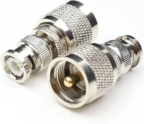
This image shows different PL259 and BNC adapter configurations used for coaxial cable conversion. Selecting the correct connector gender, impedance, and application ensures reliable RF signal transmission.
PL259, also associated with the UHF connector family, is widely used in:
- amateur radio equipment
- HF transceivers
- antenna tuners
- large coaxial cable assemblies
- traditional antenna systems
BNC connectors are more common in:
- RF test instruments
- oscilloscopes
- signal monitoring equipment
- portable measurement devices
- communication equipment
A typical connection path may look like:
Radio equipment → PL259 cable → PL259 to BNC adapter → BNC test equipment
or:
BNC instrument cable → BNC to PL259 adapter → radio antenna system
The adapter provides mechanical compatibility between these interfaces, but it does not automatically correct every RF mismatch.
Why Do Radio Users Convert PL259 and BNC Interfaces?
This creates a common situation:
A radio engineer needs to test an antenna cable using equipment with a BNC input.
Instead of replacing the entire cable assembly, a PL259 to BNC adapter provides a fast conversion method.
However, the adapter should be selected according to the actual RF path.
A common purchasing mistake is searching only for “PL259 to BNC” without checking the connector arrangement.
The actual requirement may be:
- PL259 male to BNC female
- PL259 male to BNC male
- SO239 female to BNC male
- BNC female to PL259 male
These are different products even though the search terms appear similar.
Why Does Adapter Selection Depend on Both Connectors and Applications?
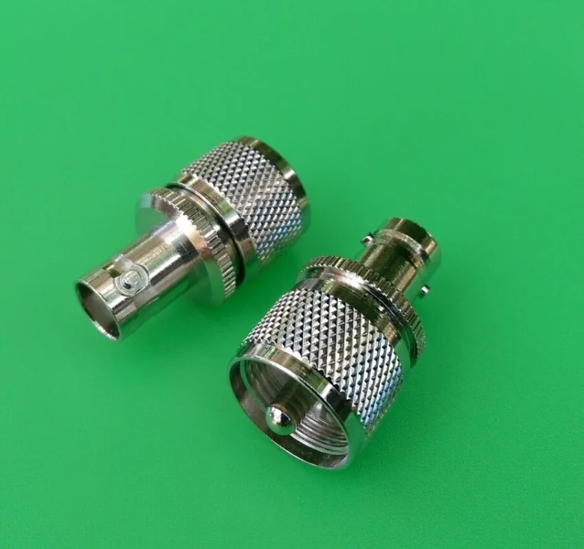
Connector names describe the interface family, but they do not fully describe the application.
Before ordering a PL259 adapter, confirm:
| Check Item | Question to Confirm |
| PL259 side | Is the equipment using PL259 plug or SO239 socket? |
| BNC side | Does the equipment require BNC male or female? |
| Impedance | Is the RF system 50Ω? |
| Cable type | RG58, RG213, LMR400 or another coax? |
| Frequency | What is the highest operating frequency? |
| Installation | Temporary test connection or permanent installation? |
A PL259 adapter used for a short laboratory test has different requirements from one installed outdoors on an antenna feed line.
For example, a small BNC instrument cable usually creates little mechanical load. A heavy RG213 cable connected through a small adapter may place continuous stress on the connector interface.
The connection may work electrically at first, but repeated mechanical force can loosen the interface over time.
Separate Mechanical Conversion From RF Compatibility
A connector adapter solves one problem:
Different physical interfaces.
It does not solve:
- incorrect impedance
- unsuitable frequency range
- poor cable selection
- antenna mismatch
- excessive adapter stacking
This distinction is important because RF failures are not always obvious.
A continuity test may show:
- center conductor connected
- shield connected
- no short circuit
But the assembly can still show unexpected VSWR or insertion loss at higher frequencies.
For RF applications, the complete signal path matters:
Connector + Adapter + Cable + Termination + Equipment
A PL259 to BNC adapter is only one part of that chain.
How Do PL259, SO239, and BNC Interfaces Work Together?
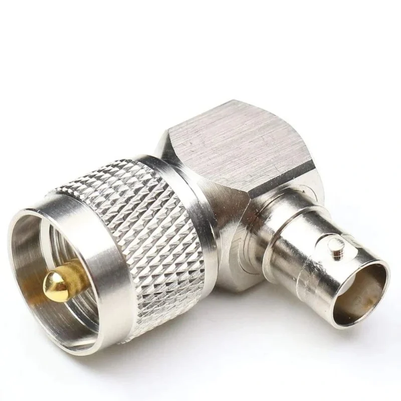
Understanding the relationship between PL259 and SO239 helps avoid one of the most common ordering errors.
PL259 and SO239 are normally used as a matching pair.
Identify the Relationship Between PL259 and SO239 Connectors
PL259 is generally the cable-side male connector.
SO239 is the matching female socket commonly mounted on equipment.
When someone asks for a “PL259 adapter,” they may actually need an SO239 conversion because the equipment side determines the connector interface.
This difference matters during procurement.
A buyer requesting:
“Need PL259 to BNC adapter”
may receive an unsuitable part if the supplier assumes the wrong direction.
Why Is PL259 Commonly Called a UHF Connector?
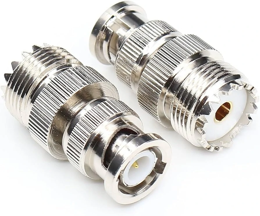
This image shows an SO239 to BNC adapter solution. SO239 connectors are commonly paired with PL259 plugs in HF radio applications, while BNC interfaces are widely used in RF test instruments and communication equipment.
The term UHF connector can create confusion.
Historically, the “UHF” naming came from older radio terminology.
Today, PL259 connectors are mainly associated with:
- HF radio
- VHF applications
- antenna systems
- general-purpose coaxial connections
The connector name alone should not be interpreted as a GHz performance rating.
For higher-frequency RF systems, engineers normally evaluate:
- connector structure
- dielectric design
- VSWR
- insertion loss
- cable compatibility
rather than relying only on the connector family name.
How Do PL259, SO239, and BNC Interfaces Work Together?
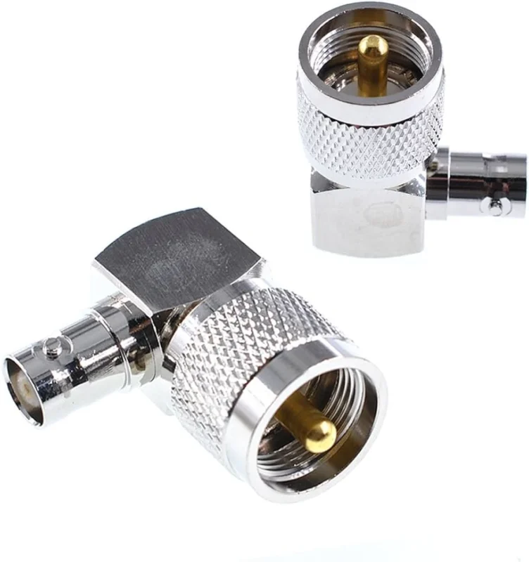
The difference between PL259 and BNC is not only the external shape. The locking method, mechanical structure, and typical installation environment are different.
A suitable adapter must maintain both sides of the connection correctly.
Compare BNC Connection Style With PL259/UHF Connection Style
PL259 and BNC are designed around different usage habits.
PL259 uses a threaded coupling mechanism. After connection, the outer shell is tightened to keep the connector mechanically stable.
BNC uses a bayonet locking system. The user only needs to push and rotate the connector to lock it.
This makes BNC convenient for test environments where connections are changed frequently, while PL259 is commonly preferred for antenna systems where a stronger mechanical connection is useful.
| Connector | Locking Method | Typical Application | Common Cable Usage |
| PL259 / SO239 | Threaded coupling | HF radio, antenna systems | RG58, RG213, LMR series |
| BNC | Bayonet lock | Test equipment, portable RF devices | RG58, RG174, small coax cables |
| SMA | Threaded coupling | RF modules, wireless equipment, test cables | RG316, RG178, semi-flex cables |
| N Type | Threaded coupling | Outdoor RF systems, higher power applications | RG8, LMR400, larger coax |
The adapter allows these connector families to work together, but the mechanical differences should be considered during installation.
For example, a PL259 cable connected to a lightweight BNC instrument through an adapter may create a hanging load. In bench testing this is usually acceptable, but in permanent installations the cable should be supported separately.
How Do You Choose the Correct PL259 to BNC Adapter Direction?
A large percentage of adapter purchasing errors come from choosing the connector name but ignoring the connection direction.
The phrase “PL259 to BNC adapter” describes two connector families, but it does not always describe which side is male or female.
Match PL259 Cable Side and BNC Equipment Side Correctly
Before selecting an adapter, identify what is already installed on both devices.
Examples:
| Existing Connection | Required Adapter |
| PL259 cable → BNC instrument port | PL259 to BNC adapter |
| BNC test cable → SO239 radio socket | BNC to PL259 adapter |
| SO239 panel socket → BNC cable | SO239 to BNC conversion |
| PL259 cable → BNC cable | Check both connector genders |
A supplier should receive a complete description instead of only a keyword.
For procurement documents, a specification such as:
PL259 male to BNC female adapter, 50Ω, nickel-plated body, for RF cable conversion
is much clearer than:
UHF converter
Select Reverse-Direction Adapters When the BNC Side Is the Cable Interface
The terms pl259 to bnc adapter and bnc to pl259 adapter often create confusion.
From an online search perspective, they appear to describe opposite products.
From a manufacturing perspective, the important factor is the physical mating arrangement.
For example:
A technician has a BNC cable from a signal generator but needs to connect it to a radio with an SO239 input.
The required solution is not determined by the search order. It depends on the actual connection path.
This is why experienced RF buyers usually provide:
- connector A
- connector B
- gender
- cable type
- application
instead of only naming the adapter direction.
PL259 to BNC Adapter Selection Matrix
The following table can help buyers quickly narrow down the suitable conversion method.
| Application | Recommended Choice | Main Consideration |
| PL259 antenna cable connected to BNC instrument | PL259 to BNC adapter | Confirm BNC gender and 50Ω system |
| BNC test cable connected to radio equipment | BNC to PL259 adapter | Check SO239 interface |
| Outdoor antenna installation | Cable assembly or fixed adapter solution | Reduce mechanical stress |
| SDR equipment connection | Check SMA/UHF transition | Connector family may differ |
| Temporary laboratory testing | Adapter | Fast conversion and easy replacement |
The table highlights an important point: an adapter is not always the best answer.
If the connection will remain installed for months or years, a dedicated cable assembly may provide better mechanical stability.
How Does Impedance Affect PL259 to BNC Adapter Performance?
A connector may fit physically while still creating an electrical mismatch.
For most radio antenna systems, impedance is a key specification.
Keep Radio Antenna Systems at the Correct Impedance
Most amateur radio and RF communication systems use a 50Ω signal path.
Every component in this path should be selected for the same impedance.
A PL259 to BNC adapter used in a 50Ω RF system should maintain the same impedance environment.
However, BNC connectors are also widely used in 75Ω video applications.
This creates a common misunderstanding:
A connector that physically connects does not necessarily mean it is electrically suitable.
Check Coax Cable Specifications Before Selecting Adapters
The coaxial cable behind the connector also affects the final result.
Before selecting a PL259 adapter, confirm:
- cable diameter
- cable impedance
- operating frequency
- power level
- installation environment
For example:
A PL259 connector used with a large RG213 cable has different mechanical requirements compared with a small RG58 cable.
The connector body, cable entry size, and strain relief must match the cable construction.
A visually similar adapter may not fit correctly when assembled with different coax sizes.
When Should You Use a PL259 to BNC Adapter Instead of Replacing the Cable?
A connector adapter is often the fastest way to solve an interface mismatch, but it is not always the right choice for a finished RF system.
In many radio projects, the adapter appears because the equipment was purchased at different times.
For example:
A user may already have an antenna cable with a PL259 connector installed years ago. Later, a new RF meter or analyzer arrives with a BNC input. Replacing the entire cable is unnecessary if the existing coax is still suitable.
In this situation, a PL259 to BNC adapter is a practical conversion method.
The decision changes when the cable is heavy, the connection is permanent, or the system will be exposed to vibration or outdoor conditions.
Use an Adapter When the Connection Needs Flexibility
For laboratory work, field testing, and temporary setups, adapters are useful because they allow existing RF equipment to be reused.
Typical cases include:
- connecting a ham radio antenna cable to BNC test equipment
- checking signal paths during troubleshooting
- switching between different measurement instruments
- testing equipment before building a dedicated cable assembly
A technician may have several cables available:
- PL259 terminated coax
- BNC test leads
- SMA measurement cables
Building a new cable for every test condition is inefficient.
An adapter kit solves this problem by allowing engineers to quickly change the connection path.
However, the adapter should be considered part of the RF chain, not just a mechanical accessory.
The signal path becomes:
Radio → Cable → PL259/BNCAdapter → Instrument
Every additional connection introduces another interface that may need inspection.
For normal radio work, this is usually acceptable. For precision measurement, the adapter quality and installation condition become more important.
Replace the Adapter With a Cable Assembly When Mechanical Stress Becomes the Problem
A common mistake happens with large coaxial cables.
A small adapter may electrically connect a large cable, but the mechanical load can become an issue.
Examples:
- RG213 cable hanging from a BNC adapter
- LMR400 cable connected through multiple transitions
- outdoor antenna cable exposed to wind movement
The connector is not only carrying the RF signal.
The cable manufacturer can match:
- connector type
- cable diameter
- termination method
- strain relief
- installation environment
This avoids forcing an adapter to handle a job it was not designed for.
Limit the Number of RF Adapter Conversions in One Signal Path
Using one PL259 to BNC adapter is normally straightforward.
The problem begins when multiple adapters are stacked together.
may work during basic testing, but every additional interface creates another possible variable.
Possible issues include:
- increased insertion loss
- additional reflection points
- loose mechanical connections
- difficult troubleshooting
This does not mean adapters should be avoided.
The practical approach is simple:
Use adapters to solve a specific connection problem. Avoid creating a long chain of conversions when a suitable cable assembly can provide a cleaner RF path.
Adapter or Cable Assembly? A Practical Decision Guide
| Application Condition | Recommended Option | Reason |
| Short laboratory connection | Adapter | Fast and reusable |
| Temporary antenna testing | Adapter | Easy equipment switching |
| Heavy coax cable | Cable assembly | Reduces connector load |
| Outdoor fixed installation | Cable assembly | Better mechanical protection |
| Repeated RF measurements | Cable assembly | More consistent test conditions |
This table is especially useful during purchasing.
A low-cost adapter may solve the immediate connection problem, but the installation environment determines whether it remains suitable after months of use.
How Do PL259 to BNC Adapters Compare With Other RF Adapter Options?
PL259 to BNC is only one type of coaxial conversion.
Different connector families exist because RF equipment has developed around different mechanical and electrical requirements.
Compare PL259 to BNC With PL259 to SMA Conversion
PL259 and SMA usually appear in different application areas.
However, the smaller size of SMA does not automatically mean it is suitable for every application.
The final performance depends on:
- adapter construction
- cable selection
- frequency range
- connector quality
- termination method
A connector conversion should always follow the requirements of the complete RF system.
Compare PL259 Adapters With SO239 Conversion Solutions
SO239 is the equipment-side counterpart commonly used with PL259.
This creates another common purchasing misunderstanding.
A customer may request:
“Need PL259 adapter.”
But the actual requirement may be:
- SO239 panel connector to BNC cable
- BNC cable to radio socket
- PL259 cable conversion
The supplier needs to know which side is installed on the equipment.
The correct specification should describe the actual connection:
Example:
SO239 female to BNC male adapter, 50Ω, for radio equipment connection.
When Should Buyers Consider a General RF Adapter Instead?
The term RF adapter covers a wide range of products, including:
- SMA adapter
- BNC adapter
- N type adapter
- TNC adapter
- UHF adapter
PL259 adapters are mainly found in radio and antenna applications.
Other RF adapters may be selected for:
- communication systems
- laboratory testing
- microwave applications
- wireless equipment
The connector family should match the operating environment.
A PL259 connection that works well in an HF antenna system may not be the correct choice for a GHz-level measurement setup.
Confirm Electrical Continuity Before RF Testing
Basic inspection should include:
- center conductor continuity
- outer conductor continuity
- insulation condition
- short circuit check
These checks are useful for incoming inspection.
Use RF Measurement When the Application Requires It
For critical RF systems, measurement equipment may be required.
Typical checks include:
- VSWR
- return loss
- insertion loss
A VNA test can show whether the adapter introduces unexpected reflection into the system.
For example, an adapter used only for HF communication may require less verification than one used in a controlled RF measurement setup.
The inspection standard should match the application risk.
PL259 to BNC Adapter Incoming Inspection Checklist
| Inspection Item | Record |
| Adapter Structure | PL259 / BNC type |
| Connector Gender | Male / Female |
| Impedance | 50Ω / Other |
| Cable Compatibility | RG / LMR series |
| Frequency Requirement | Operating MHz/GHz |
| Mechanical Condition | Pass / Fail |
| Continuity Test | Pass / Fail |
| VSWR Requirement | Measured value if needed |
| Application | Radio / Test / Antenna |
This type of checklist is useful for engineering approval and purchasing records.
How Should Buyers Describe PL259 to BNC Adapter Requirements?
Many RF purchasing mistakes start with incomplete descriptions.
A request such as:
“Need UHF adapter”
does not provide enough information.
The supplier still needs to determine:
- Which UHF connector?
- Which BNC gender?
- What impedance?
- What cable?
- What frequency?
FAQ
Is PL259 the same as UHF connector?
PL259 is commonly classified as part of the UHF connector family. SO239 is the matching socket. The name comes from older radio terminology and does not indicate modern high-frequency capability.
Will a PL259 to BNC adapter affect antenna SWR?
It can. Poor contact, incorrect impedance, damaged connectors, or unsuitable RF transitions may increase reflection and affect SWR results.
Is an adapter better than making a new coax cable?
For temporary conversion, an adapter is usually practical. For permanent installations, heavy cables, or repeatable measurements, a dedicated cable assembly is often a better choice.
Why does the adapter connect correctly but RF performance is poor?
Possible reasons include cable mismatch, impedance differences, damaged contacts, poor shielding, or limitations elsewhere in the RF path.
