
A connector can look perfectly acceptable on the workbench and still create problems after it is installed into a complete antenna system.
This happens often with SO239 connector assemblies. The PL259 plug threads in correctly, continuity checks pass, and the radio can transmit. The issue appears later when the system is operated at higher power, exposed to vibration, or tested for antenna matching. A loose mechanical fit, unsuitable coax cable, or incorrect adapter selection can introduce unexpected VSWR changes and signal loss.
For engineers and buyers, the key point is simple: an SO239 connection is not only a mechanical interface. It is part of the complete RF path.
Before ordering an SO239 connector, it is necessary to confirm how it will mate with the PL259 connector, what cable will be used, and whether the complete assembly matches the intended antenna application.
How Does an SO239 Connector Connect With PL259 in RF Systems?
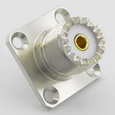
This image shows an SO239 female RF connector with a square flange mounting design. The connector provides a fixed RF interface for PL259 cable plugs in antenna and communication systems.
The SO239 connector and PL259 connector are normally used as a matching pair in radio and antenna systems.
An SO239 connector is the female socket side. It is commonly installed on equipment panels, radio chassis, antenna tuners, and RF accessories. The PL259 connector is the male plug side, usually terminated onto a coaxial cable.
A common sourcing mistake is to treat SO239 and PL259 as interchangeable names. They describe different sides of the same connector family.
When a buyer requests a “UHF connector,” a supplier still needs more information:
- Is the requirement for SO239 socket or PL259 plug?
- Is it for equipment mounting or cable termination?
- What coax cable diameter is required?
- What frequency range will the assembly operate at?
A connector that fits mechanically may still be unsuitable electrically.
Why Is the UHF Connector Name Sometimes Confusing?
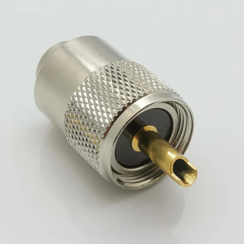
The term UHF connector creates confusion because the name comes from an older RF naming system rather than modern frequency classification.
In current RF applications, “UHF connector” commonly refers to the connector family containing:
- PL259 male plug
- SO239 female socket
The name does not mean the connector is designed specifically for today’s UHF frequency applications.
This distinction matters during RF selection.
A connector labeled “UHF” may physically connect a coax cable, but the final RF performance depends on several factors:
| Parameter | Why It Matters |
| Frequency range | Determines whether the connector is suitable for the operating band |
| Impedance | Prevents mismatch in the RF path |
| Cable type | Affects termination compatibility and loss |
| Installation method | Influences mechanical reliability |
| Antenna matching | Directly affects VSWR |
For example, an SO239/PL259 combination may be a practical choice for many HF radio applications, but it should not automatically replace connectors designed for higher-frequency microwave systems.
The connector family must be selected according to the complete application rather than the connector name alone.
How Should Engineers Separate Mechanical Compatibility From RF Performance?
A connector that mates correctly is only the first step.
During purchasing, many problems occur because teams check only physical compatibility:
- The thread size matches.
- The plug screws in.
- The cable can be attached.
- The assembly passes continuity.
However, RF performance depends on more than connection.
The complete signal path includes:
Radio → Connector → Cable → Adapter → Antenna
Any part of this path can affect the final result.
Important parameters include:
- impedance matching
- cable attenuation
- connector quality
- contact alignment
- installation stress
- operating frequency
- antenna tuning condition
For antenna systems, VSWR measurement is often more meaningful than a simple electrical continuity check.
A continuity test can confirm that the conductor is connected. It cannot confirm whether the RF energy is transferring efficiently at the operating frequency.
This is especially important when adapters are added.
For example, converting an SO239 interface to another RF connector through multiple adapters may solve a mechanical problem, but each additional connection introduces another possible mismatch point.
How Do You Match an SO239 Connector With the Correct PL259 Cable Plug?
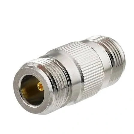
This image shows a UHF RF adapter used for connector conversion. When selecting an SO239 adapter, engineers should confirm connector gender, impedance, frequency range, and application requirements.
The rear body, clamp structure, and center conductor dimensions may be different.
For custom cable assemblies, the cable should be confirmed before the connector is selected.
This avoids a common production issue: the connector interface is correct, but the cable termination is not suitable.
For example, an SO239-compatible PL259 assembly for RG58 is not automatically suitable for RG213. The connector body, cable entry size, and mechanical support must match the cable construction.
SO239 / PL259 Connector Matching Matrix
| Application | Recommended Connection | Main Check |
| Radio equipment panel | SO239 socket + PL259 cable plug | Confirm interface and mounting |
| Antenna cable connection | PL259 terminated coax cable | Match coax diameter |
| Adapter conversion | SO239 adapter + target connector | Check impedance and frequency |
| RF equipment replacement | Same mounting style SO239 | Verify mechanical dimensions |
| Custom cable assembly | PL259 + selected coax cable | Confirm termination method |
| Outdoor installation | Weather-protected connection | Check environmental requirements |
This matrix can be used during RF purchasing discussions to avoid incorrect connector substitutions.
How Does Coax Cable Selection Change the Result of an SO239 Connection?
A PL259 connector may fit an SO239 socket perfectly, but the cable behind the connector often decides whether the assembly works reliably.
This is a point that is easy to miss during purchasing.
Many RF projects start with a connector request:
“Need SO239 connector.”
The missing information is usually the cable.
A connector designed for RG58 is not simply replaced with another PL259 connector designed for RG213. The front mating interface may look identical, but the rear section, cable entry size, and termination structure can be completely different.
During production, the cable and connector should be treated as one assembly.
The supplier needs to confirm:
- coaxial cable model
- outer diameter
- shielding structure
- termination method
- required bending condition
- installation environment
For SO239 and PL259 applications, common cable choices include:
| Cable Type | Typical Use | Selection Note |
| RG58 | Short antenna connections, general radio use | Flexible and easy to route |
| RG8X | Medium power radio applications | Smaller alternative to larger coax |
| RG213 | Lower-loss antenna feed systems | Requires larger connector rear structure |
| LMR series | Longer-distance RF connections | Cable specification must match connector |
The cable is often the limiting factor before the connector itself.
A connector with a suitable interface but incorrect cable matching can create problems such as weak mechanical retention, unstable contact, or inconsistent production quality.
Why Should the RF Path Be Checked Instead of Only the Connector Interface?
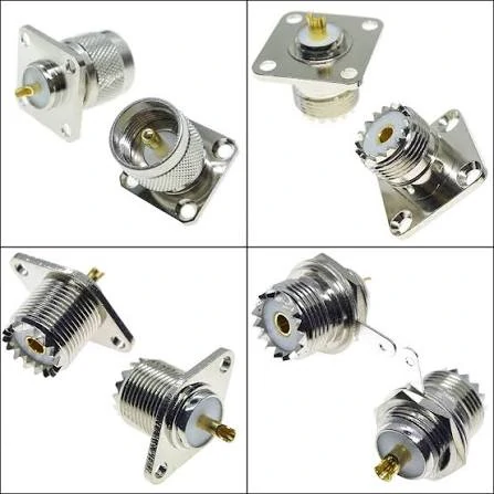
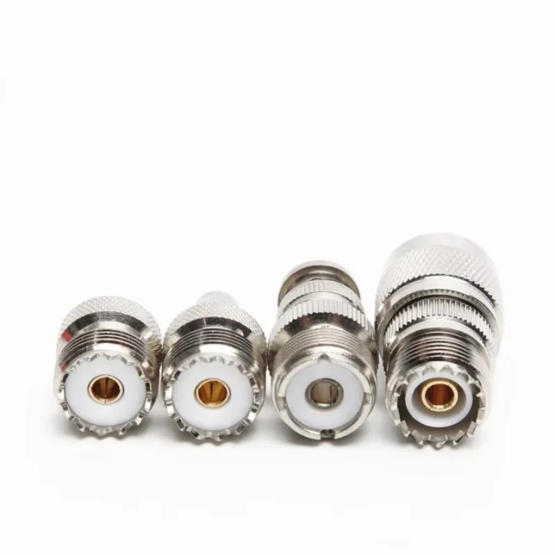
This image presents different views of SO239 panel mount connectors, including flange mounting styles and threaded connection structures. These connectors are widely used in radio equipment, antenna tuners, and RF accessories.
A common purchasing misunderstanding is assuming that matching connectors means matching RF performance.
It does not.
An SO239 connector only confirms one mechanical connection point. The actual RF path includes every component between the radio and antenna:
Transceiver → SO239 → PL259 → Coax Cable → Antenna
A problem in any section can affect the final result.
Typical causes include:
- incorrect cable impedance
- poor soldering or crimping
- damaged center contact
- excessive adapter stacking
- cable routing stress
- antenna mismatch
For traditional radio systems, maintaining a 50Ω path is usually the starting point.
However, impedance alone is not enough.
The engineer should also consider:
- operating frequency
- cable length
- connector quantity
- adapter quantity
- environmental conditions
A short cable assembly used for an amateur radio station and a long outdoor antenna feed line may use similar connectors but have very different requirements.
When Does an SO239 Connector Become the Wrong Choice?
SO239 remains popular because many radio systems were built around this interface.
That does not mean it fits every project.
The decision usually depends on the application.
For example:
A replacement cable for an existing HF transceiver may require a PL259 connector because compatibility with existing equipment is the priority.
A compact RF module operating at several GHz may require a smaller precision connector instead.
A measurement system may require a connector with more controlled RF characteristics.
The following comparison helps during initial selection:
| Connector Family | Common Application | Suitable Situation | Possible Limitation |
| SO239 / PL259 | HF radio, antenna equipment | Existing radio infrastructure | Larger size, limited high-frequency use |
| SMA | RF modules, test fixtures | Compact RF assemblies | Requires precise cable matching |
| BNC | Test equipment | Frequent connection/disconnection | Mechanical locking differs |
| N Type | Outdoor RF systems | Higher-frequency outdoor links | Larger installation size |
The important point is not replacing SO239 everywhere.
It is avoiding using it outside its practical application range.
How Do SO239 Adapters Help Connect Different RF Interfaces?
Existing equipment often creates situations where connector conversion is necessary.
Before selecting an RF adapter, confirm:
| Check Item | Reason |
| Connector gender | Prevent incorrect mating |
| Impedance | Maintain RF system compatibility |
| Frequency range | Avoid unsuitable operation |
| Mechanical size | Ensure proper installation |
| Application | Confirm whether it is for antenna, test, or equipment use |
A low-frequency antenna connection may tolerate a simple adapter solution.
A precision RF measurement setup usually requires fewer transitions.
How Should Buyers Describe an SO239 Adapter Requirement?
“Need a UHF adapter” is usually not enough information for production.
The term UHF can refer to the connector family rather than the exact interface required.
A supplier still needs to know:
- SO239 or PL259?
- Male or female?
- Cable mount or panel mount?
- What connector is on the other side?
- What frequency will the system operate at?
A practical RF specification should look closer to this:
SO239 female to SMA male adapter, 50Ω, for antenna equipment connection, confirm operating frequency before production.
For custom sourcing, the BOM information should include:
| Specification | Example |
| Interface A | SO239 female |
| Interface B | SMA male |
| Impedance | 50Ω |
| Application | Radio antenna system |
| Installation | Equipment panel |
| Frequency requirement | Confirm before order |
Clear specifications reduce the chance of receiving a connector that fits physically but fails in the actual RF application.
How Can Installation Problems Be Found Before Field Use?
Many SO239 connection issues are not discovered during assembly.
They appear after installation.
A connector may pass a basic continuity test but still have problems caused by:
- poor contact pressure
- damaged threads
- loose mounting
- cable pulling force
- moisture exposure
Before field installation, a practical inspection should include:
- Check connector body condition
- Verify PL259 and SO239 engagement
- Inspect center contact alignment
- Confirm cable termination quality
- Measure antenna system parameters when required
For antenna systems, VSWR testing is often more useful than checking only electrical continuity.
Continuity tells you the conductor is connected.
It does not tell you whether the RF energy is transferring correctly at the working frequency.
SO239 Installation Risk Check Table
| Inspection Item | Pass Condition | Possible Issue If Failed |
| Thread engagement | Plug fully tightened | Loose mechanical connection |
| Center contact | Proper alignment | Increased mismatch risk |
| Cable termination | Firm and stable | Pull-out or intermittent contact |
| Impedance | 50Ω system maintained | RF reflection |
| VSWR test | Within application target | Antenna system issue |
| Environmental protection | Suitable for installation area | Corrosion or moisture damage |
This checklist is useful before releasing an antenna cable assembly into production or field installation.
Where Does SO239 Still Make Sense Compared With Other RF Connectors?
A connector choice is often inherited from the equipment around it.
A radio manufacturer may have used SO239 for years. The antenna accessories, replacement cables, and service tools in the field are already built around that interface.
In this situation, changing the connector standard does not necessarily improve the system.
The replacement cable still needs to fit the existing radio.
The antenna tuner still needs the same connection.
The operator still needs accessories that are easy to find.
That is why SO239 and PL259 remain common in many HF and amateur radio applications.
However, when a new RF product is designed, engineers usually look beyond mechanical compatibility.
The connector size, frequency capability, installation space, and cable assembly method all become part of the decision.
A few typical comparisons:
| Connector | Where It Is Commonly Found | Practical Consideration |
| SO239 / PL259 | HF radio equipment, antenna systems | Good compatibility with existing radio products |
| SMA | RF modules, compact devices, test assemblies | Smaller size but requires more precise assembly control |
| BNC | Laboratory equipment, communication systems | Convenient for repeated connection and removal |
| N Type | Outdoor antenna systems, RF links | Better suited for many demanding environments |
For a repair project, keeping SO239 may be the most reasonable choice.
For a new microwave design, another connector family may be more suitable.
The decision depends on the equipment, not on which connector looks newer.
What Information Do RF Buyers Need Before Ordering SO239 Parts?
Many quotation problems are caused by missing details rather than product availability.
A customer may send:
“Need UHF connector.”
From a purchasing perspective, this request may seem complete.
From a connector supplier’s perspective, several details are still unknown.
The term “UHF connector” could refer to:
- SO239 socket
- PL259 plug
- complete cable assembly
- adapter product
The supplier also needs to know what happens after the connector is delivered.
Will it be:
- installed on a radio panel?
- terminated to coax cable?
- used with an adapter?
- installed outdoors?
A more useful RF request normally includes:
| Required Information | Example |
| Connector type | SO239 female / PL259 male |
| Cable | RG58, RG213, RG8X, other coax |
| Installation | Panel mount or cable end |
| System impedance | 50Ω |
| Application | Antenna, radio, test setup |
| Quantity | Prototype or production order |
This information affects the recommended structure.
For example, two PL259 connectors may look almost identical from the front side.
The difference may be inside the rear body.
One version may fit a smaller flexible coax cable. Another may be designed for a larger cable with different mechanical support.
The interface alone does not define the complete connector.
How Do Field Engineers Usually Find Problems in SO239 Connections?
A failed antenna system does not always point directly to the connector.
During troubleshooting, replacing parts randomly can become expensive, especially when the system contains several adapters and long coax runs.
A practical inspection normally starts from the complete connection path:
Radio equipment → Connector → Cable → Adapter → Antenna
Common field symptoms include:
| Problem Observed | Possible Reason |
| Connection becomes unstable after movement | Cable stress or loose mechanical fixing |
| VSWR changes after installation | Antenna tuning, cable issue, or contact problem |
| Connector cannot tighten smoothly | Thread damage or incorrect mating part |
| Different results between two assemblies | Termination consistency issue |
| Signal drops intermittently | Contact pressure or cable damage |
One situation appears frequently during maintenance:
The connector is replaced, but the problem remains.
The reason is that the original failure was not caused by the connector itself. It may have been caused by cable bending, poor strain relief, moisture entering the connection point, or an antenna adjustment issue.
A connector inspection should be part of the troubleshooting process, not the only step.
Why Does Continuity Testing Not Tell the Whole Story?
A continuity test is useful.
It confirms that the electrical path is connected.
For RF applications, however, it only checks the most basic condition.
A cable assembly can pass continuity and still show unexpected RF behavior.
The required test depends on the application.
A hobby radio installation may only require basic inspection and antenna tuning.
A production RF assembly may need documented testing before shipment.
The test method should match the risk level.
How Should SO239 Assemblies Be Documented for Repeat Orders?
Repeat purchasing becomes easier when the original assembly information is recorded.
Without records, a later order often turns into a new confirmation process.
Useful records include:
| Record Item | Example |
| Connector model | SO239 / PL259 specification |
| Cable model | RG58 or specified coax |
| Cable length | Finished length |
| Termination process | Solder / clamp type |
| Application | Radio antenna connection |
| Test requirement | VSWR or continuity |
| Production notes | Special assembly requirement |
This is especially useful when several similar connector versions exist.
A small difference in cable size, plating, mounting style, or termination method can affect whether the replacement part works directly.
SO239 Ordering Risk Review
Before releasing an order, review these five points:
| Review Point | Question to Ask | Risk If Ignored |
| Interface | Is it SO239 or PL259? | Wrong mating connector |
| Cable | Does the connector match the coax? | Poor assembly strength |
| RF requirement | What frequency is required? | Unsuitable RF performance |
| Installation | Indoor or outdoor use? | Environmental failure |
| Testing | What needs verification? | Problems discovered after installation |
This simple review is useful for both small replacement orders and larger cable assembly projects.
FAQ
Is SO239 a female connector?
Yes. SO239 is generally the female socket used on equipment, while PL259 is the matching male plug commonly installed on coaxial cables.
Why is SO239 also called a UHF connector?
The name comes from historical RF terminology. It does not mean the connector is designed for all modern UHF frequency applications.
Can SO239 be converted to SMA?
Yes. SMA to SO239 adapters and SO239 to SMA adapters are available. The impedance, frequency range, and intended application should be confirmed.
Does adding an adapter reduce RF performance?
An adapter adds another connection point in the RF path. For many general radio applications this may be acceptable, but sensitive RF measurements usually require fewer transitions.
Why does an SO239 connection show high VSWR?
The connector should be checked together with the complete RF path.
Is SO239 suitable for outdoor antenna systems?
It can be used in many outdoor radio applications, but environmental protection, sealing, and mechanical support should be considered according to the installation conditions.
Final Practical Note
SO239 remains in use because many RF systems were built around it.
Its value is not in replacing every modern connector. Its value is in providing a familiar and practical connection method for existing radio equipment and antenna systems.
For purchasing, the most useful specification is not only:
“Need SO239 connector.”
A better request includes:
- connector interface
- cable type
- impedance
- operating frequency
- installation environment
- required testing
When these details are clear, the connector selection becomes much simpler, and the final RF assembly is easier to control.
