
A TNC to SMA adapter often gets ordered after someone discovers that two RF parts almost mate — but not quite.
The antenna has a threaded TNC interface. The module, test board, receiver, or compact RF device has an SMA port. The product photo looks simple enough, so the buyer searches for a “TNC SMA converter” and expects the adapter to solve the connection. Mechanically, it may. Electrically, it may not. Direction, gender, polarity, impedance, frequency range, and port stress still decide whether the part belongs in the RF path.
That is the practical point of a TNC to SMA adapter. It does not improve a weak antenna match. It does not turn a poor cable into a low-loss assembly. It only converts one connector interface to another. The rest of the RF system still has to make sense.
How Does a TNC to SMA Adapter Connect Antennas and RF Modules?
A TNC interface and an SMA interface usually appear in different parts of a build.
TNC connectors are often selected where the threaded coupling helps resist loosening. That can be useful around antennas, field equipment, radio hardware, test fixtures, or systems exposed to vibration. SMA connectors are smaller and more common on compact RF modules, lab devices, wireless boards, small antennas, and instrument ports.
The adapter sits between those two worlds. One side mates with the TNC hardware. The other side mates with the SMA device or cable. In a clean bench setup, that sounds easy. In production or field use, several details start to matter.
A straight rigid adapter works best when the two ports are close, aligned, and not pulling against each other. If a heavy TNC cable hangs from a small SMA module port, the adapter becomes a lever. The signal may still pass, but the SMA jack can see side load, repeated bending, or solder joint stress. That is why a short TNC-to-SMA cable assembly is often safer when the mechanical angle is not controlled.
The adapter should also be treated as part of the RF path, not as a universal fix. If the antenna is poorly matched, the cable is too lossy, or the device frequency is outside the usable range, adding an adapter will not repair the problem. It may add another reflection point.
A common sourcing mistake is to check only the front interface. The buyer confirms “TNC on one side, SMA on the other,” then skips impedance and frequency. That may be enough for a rough low-frequency connection, but it is not enough for RF test, antenna validation, or production hardware. At higher frequencies, small geometry differences and extra interfaces can show up as worse return loss or unstable VSWR.
For a simple antenna-to-module connection, the basic chain should be checked like this:
| RF Path Item | What to Confirm | Why It Matters |
| TNC antenna or cable side | Male or female TNC, thread condition | Prevents wrong mating direction |
| Adapter | TNC-to-SMA direction, 50 ohm impedance | Keeps the interface and RF path consistent |
| SMA module or device side | Standard SMA or RP-SMA, male or female | Avoids center contact mismatch |
| Frequency band | Highest operating frequency | Prevents using a low-rated adapter near its limit |
| Mechanical load | Cable weight, angle, vibration | Protects the smaller SMA port |
This is not a long checklist, but it catches many wrong orders. The part may look correct in a catalog image and still be wrong once it is installed.
How Do You Choose the Correct TNC-to-SMA Direction?
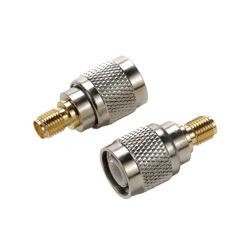
Start with the installed port, not with the keyword.
“TNC to SMA” and “SMA to TNC” are often used interchangeably in search, but the physical adapter must match the actual mating interfaces. Direction in the product name is less important than the connector gender on each side.
For the TNC side, check whether the existing port has a center pin or a center socket. Also check the threaded coupling. For the SMA side, do the same. Do not judge only by outer shape. SMA and RP-SMA confusion is especially common in antenna and wireless equipment. Standard SMA and reverse-polarity SMA may look similar in a small product photo, but the center contact arrangement is different.
The safest buying process is simple: write the two installed interfaces first, then write the adapter required between them.
If the equipment has a TNC female antenna port and the cable has an SMA male plug, the adapter is usually TNC male to SMA female. If the equipment has a TNC male cable end and the module has an SMA female jack, the adapter is usually TNC female to SMA male.
That sounds obvious, but it is where many procurement errors happen. A buyer may send “TNC to SMA adapter, 50 ohm” and assume the supplier knows the direction. The supplier cannot know it without the mating parts.
Use this matrix as a practical ordering reference:
| Installed TNC Side | Installed SMA Side | Likely Adapter Needed |
| TNC female antenna port | SMA male cable | TNC male to SMA female |
| TNC male cable | SMA female module | TNC female to SMA male |
| TNC female device port | SMA female test port | TNC male to SMA male |
| TNC male antenna lead | SMA male device lead | TNC female to SMA female |
| Unknown interface | Unknown interface | Inspect center contact before ordering |
The last row is the one that saves money. If the interface is unknown, do not guess from a search term. Ask for front photos, side photos, and a clear view of the center contact. For production orders, one wrong gender can stop the whole batch even if impedance and frequency are correct.
There is another small trap: adapters are sometimes named from the cable direction, while buyers think from the device direction. A “TNC male to SMA female” adapter and an “SMA female to TNC male” adapter may refer to the same physical part. The better habit is to list both sides clearly:
“TNC male to SMA female adapter, 50 ohm, straight body, for connecting a TNC female antenna port to an SMA male cable.”
That sentence removes most of the ambiguity. It tells the supplier the mating environment, not just the adapter name.
For low-volume testing, a small mistake may only delay a lab setup. For repeated production, it becomes more expensive. The wrong adapter can lead to rework, extra adapter stacking, mismatched BOM labels, and confusing test results. If a second adapter is added to “make it work,” the RF path becomes longer and harder to validate.
A clean TNC-to-SMA transition starts with the correct direction. After that, impedance and frequency decide whether the adapter belongs in the electrical path.
How Should 50 Ohm Matching Guide TNC to SMA Adapter Selection?
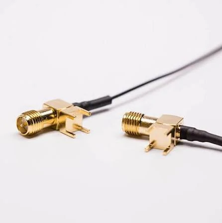
This TNC to SMA adapter cable assembly is designed for RF applications requiring conversion between TNC and SMA connector interfaces. The flexible cable structure helps reduce mechanical stress on compact SMA ports while maintaining stable signal transmission for antenna systems, wireless modules, and RF test equipment.
The adapter should not be the only 50 ohm part in the chain.
Most TNC and SMA RF adapters used for antenna, module, radio, and test work are specified as 50 ohm. That does not mean the whole setup is automatically matched. The cable, antenna, device port, test equipment, and any extra adapter in the path still need to belong to the same impedance system.
A 50 ohm TNC to SMA adapter can pass continuity and still sit in a poor RF path. The usual problem is not the adapter alone. It is the mix of parts around it: an antenna with unknown match, a long cable with avoidable loss, a module port using a different polarity, or a low-cost adapter stack added after the BOM was already finished.
For procurement, “50 ohm” should be written into the request, not assumed from the connector name. TNC and SMA are strongly associated with 50 ohm RF work, but that is not a reason to skip the line item. A clear BOM note is safer:
TNC male to SMA female adapter, 50 ohm, straight body, for external antenna to SMA RF module connection, target band DC–6 GHz.
That wording gives the supplier a much better chance of matching the part to the application.
The next question is what happens after the adapter is added. Every additional interface can create a small discontinuity. At low frequencies or in non-sensitive links, that may not matter much. In a measured RF system, it can appear as worse return loss, higher VSWR, or slightly more insertion loss.
That is why a TNC to SMA adapter should be tested in the same type of path where it will be used. A loose bench check does not represent a mounted antenna, a moving cable, or a production fixture that gets mated hundreds of times.
Use this table as a practical risk screen before approving the part:
| Condition | RF Risk | What to Check |
| Single adapter in a short antenna path | Low to medium | Confirm 50 ohm, gender, polarity, and frequency rating |
| Adapter used near upper frequency limit | Medium | Check S11, VSWR, and insertion loss at target band |
| Several adapters stacked together | High | Reduce adapter count or redesign the transition |
| Heavy TNC cable attached to small SMA port | High | Use a short cable assembly for strain relief |
| Unknown antenna match | Medium to high | Measure return loss before blaming the adapter |
| Mixed RF and video/CATV accessories | High | Confirm impedance and connector family before use |
The table is not a lab standard. It is a buying filter. If the setup falls into a high-risk row, do not approve the adapter from catalog photos only.
When Should You Use a TNC to SMA Adapter Instead of a Cable Assembly?
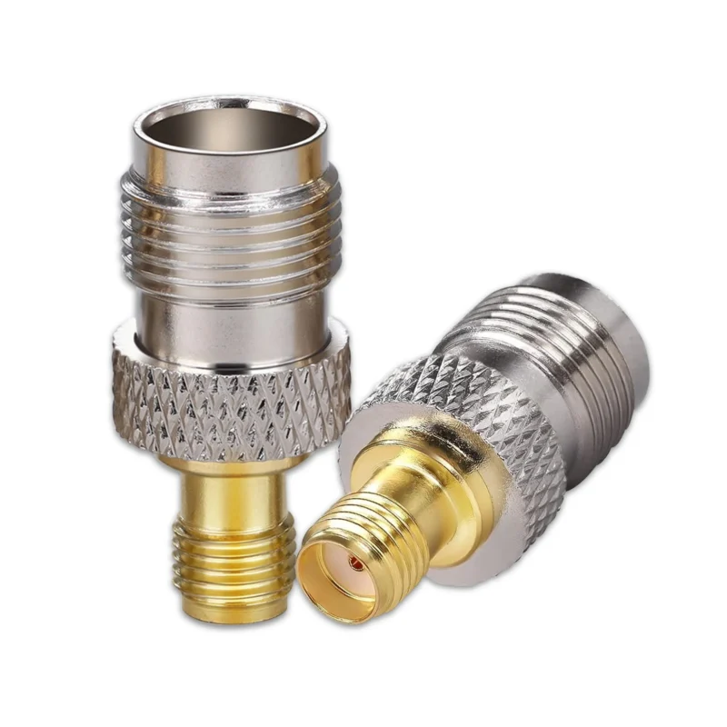
A rigid adapter is useful when the connection is short, straight, and temporary.
On a test bench, that can be exactly what you need. A technician may need to connect a TNC antenna port to an SMA test device for a quick measurement. The two ports are close. The cable is not pulling sideways. The adapter is easy to install, easy to remove, and does not introduce extra cable length.
That is the clean use case.
The risk begins when the adapter is asked to solve a routing problem. A rigid adapter cannot absorb movement. It cannot bend around an enclosure wall. It cannot relieve cable weight. If the TNC side is connected to a thick or semi-rigid cable and the SMA side is mounted on a small PCB, the SMA port may carry more mechanical load than expected.
The RF result may still look acceptable at first. The real issue appears after installation, transport, vibration, or repeated mating. The SMA nut loosens. The board connector tilts. The solder joint sees stress. The operator adds another adapter to change the angle. Now the RF path has more interfaces and the mechanical problem is still there.
A short cable assembly is usually the better answer in that situation.
The choice is not about which one is “better.” It depends on the job.
| Application Condition | Better Choice | Reason |
| Short, aligned bench transition | Rigid adapter | Fast setup with minimal extra length |
| PCB-mounted SMA module | Short cable assembly | Reduces leverage on the board connector |
| Outdoor antenna line | Cable assembly | Easier routing, sealing, and strain relief |
| Prototype testing with changing ports | Adapter | Quick conversion during development |
| Repeated production test | Cable assembly or fixed test lead | Better repeatability and less port wear |
| Unknown final mounting angle | Cable assembly | More tolerance for routing changes |
For a buyer, the most useful question is not “adapter or cable?” It is: where will the mechanical force go?
If the force goes into a strong metal panel, a rigid adapter may be fine. If it goes into a small SMA jack on a wireless module, use caution. SMA ports are compact for a reason. They are not meant to carry the weight and stiffness of every cable attached upstream.
There is also a test repeatability angle. In a production fixture, operators may connect and disconnect the RF path many times per day. A rigid adapter can be convenient, but it can also wear the device port if alignment is poor. A short cable test lead, properly supported, may protect the device and make handling more consistent.
Adapter stacks should be avoided whenever possible. One adapter may be reasonable. Two adapters may be a temporary fix. Three adapters in one antenna path usually means the BOM needs to be cleaned up. Each extra interface adds a possible looseness point, reflection point, and inspection question.
How Does Frequency Range Affect TNC to SMA Adapter Use?
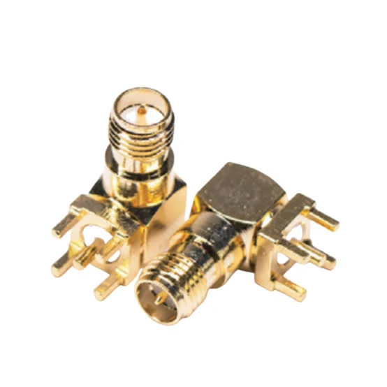
This right angle SMA PCB mount connector is designed for compact RF equipment and circuit board applications. The through-hole mounting structure provides mechanical stability and reliable RF signal transmission for wireless modules, test boards, and communication devices.
Do not assume the SMA side defines the frequency limit.
SMA connectors are often associated with higher-frequency RF work, but a TNC to SMA adapter is limited by the full adapter design, the TNC side, internal geometry, contact quality, plating condition, and the connected cable or device. A small SMA interface on one end does not turn the whole transition into a high-frequency precision adapter.
For common antenna and wireless work, many buyers are dealing with bands such as VHF/UHF, GPS, Wi-Fi, ISM, LTE, or general low-power RF module testing. The adapter only needs to support the actual band with enough margin. For lab measurements or sensitive validation, the margin should be higher, and the adapter should be checked with real measurement data.
A continuity meter only confirms that the center conductor and shield are connected correctly and not shorted. It does not confirm return loss. It does not confirm insertion loss. It does not show how the adapter behaves at 3 GHz, 6 GHz, or another working band.
That distinction matters. A part can pass the basic electrical check and still be a poor choice for a measured RF path.
A practical frequency margin rule can help during sourcing:
| Frequency Margin Ratio | Meaning | Buying Action |
| Below 1.0x | Adapter rating is below the operating frequency | Do not use |
| 1.0x–1.2x | Little margin | Use only with test data and low-risk application |
| 1.2x–1.5x | General margin | Acceptable for many antenna/module links |
| 1.5x–2.0x | Safer margin | Better for test setups and repeatable builds |
| Above 2.0x | Strong margin | Preferred for sensitive RF validation |
Frequency Margin Ratio = Adapter Rated Frequency ÷ Highest Operating Frequency
If a system operates at 5.8 GHz and the adapter is rated to 6 GHz, the margin is only about 1.03x. That may work in a simple link, but it leaves little room for assembly variation, connector wear, or measurement sensitivity. If the same system uses an adapter rated well above the operating band, the buyer has more practical margin.
This does not mean higher GHz is always better in every way. A higher-rated adapter still needs the correct gender, polarity, impedance, and mechanical fit. It also needs to come from a controlled source, not just a listing with an aggressive frequency claim.
For RF test use, ask for the measurement condition. A supplier saying “6 GHz adapter” is less useful than a supplier confirming the adapter type, impedance, sample test method, and whether S11/S21 can be checked at the target frequency. For production buying, the inspection requirement should match the real risk. A simple antenna adapter may only need visual inspection and continuity. A test fixture adapter may need documented RF performance.
The better habit is to specify the real operating band, not only the maximum catalog rating. Write “for 2.4 GHz antenna module connection” or “for DC–6 GHz RF test path” in the inquiry. That tells the supplier how strict the adapter selection needs to be.
A TNC to SMA adapter is a small part, but it is still part of the RF design. Treat it as a measured transition when the frequency, mismatch, or production repeatability matters.
How Do TNC to SMA Adapters Compare With Other RF Conversions?
TNC to SMA is not the same buying problem as every other RF adapter.
A TNC to BNC adapter usually appears when a threaded TNC port needs to connect with bayonet-style BNC test equipment or older RF hardware. That is often a test-conversion problem. A TNC to SMA adapter is more often an antenna-to-module or rugged-interface-to-compact-device problem.
The mechanical expectation is different. TNC keeps the threaded coupling. SMA keeps the compact RF interface. The adapter bridges them, but it also brings the risk of putting a larger, heavier connector path onto a smaller SMA port.
N to TNC is another different case. N-type connectors are larger and common around antenna feeders, base station equipment, outdoor RF hardware, and higher-power coax paths. TNC is smaller than N but still more rugged than many compact board-level interfaces. A TNC-to-SMA transition usually moves toward smaller hardware, not larger hardware.
Use this comparison before making substitutions:
| Adapter Conversion | Common Use | Main Risk |
| TNC to SMA | Antenna hardware to SMA module, compact receiver, or test board | SMA port stress and polarity confusion |
| TNC to BNC | TNC equipment to BNC instrument or test cable | Bayonet interface loosening in vibration |
| N to TNC | Larger antenna feeder or outdoor RF equipment to TNC device | Size, weight, and sealing mismatch |
| SMA to BNC | SMA device to BNC lab equipment | Frequency and adapter stack limitations |
| TNC to N | TNC equipment into larger RF cable infrastructure | Mechanical bulk and routing space |
The useful point is not memorizing adapter names. It is knowing what each transition does to the system. If the conversion moves from a larger connector to a smaller one, mechanical support becomes more important. If it moves from a threaded interface to a bayonet interface, vibration and locking behavior become more important. If it adds multiple adapters to reach the final port, the RF path probably needs to be simplified.
How Can You Test a TNC to SMA Adapter Before Use?
Visual inspection comes first because damaged connectors can ruin the test before the VNA is even connected.
Check the TNC thread, coupling nut, dielectric, center contact, plating, and body tightness. Then inspect the SMA side separately. A bent SMA pin, loose female contact, scratched dielectric, or contaminated interface can create intermittent behavior that looks like a device problem.
After that, run basic electrical checks:
- center conductor continuity
- shield continuity
- center-to-shield isolation
- obvious short-circuit check
These tests are useful, but they are not RF validation. They only tell you the adapter is electrically continuous and not shorted.
A practical acceptance checklist can look like this:
| Parameter | Record |
| Adapter direction | TNC male to SMA female / TNC female to SMA male / other |
| Impedance | 50 ohm |
| SMA polarity | Standard SMA / RP-SMA |
| Target frequency | MHz or GHz band |
| S11 / return loss | dB value if tested |
| VSWR | Measured value if tested |
| S21 / insertion loss | dB value if tested |
| Mechanical inspection | Pass / fail |
| Test equipment | VNA / fixture / signal generator |
| Final result | Accept / reject |
This checklist is more useful than a vague note such as “adapter tested OK.” It gives engineering, purchasing, and quality teams the same language. If a later batch behaves differently, the team can compare actual inspection records instead of guessing.
How Do You Use TNC to SMA Adapters in Antenna Systems?
Antenna systems are where this adapter is useful — and where it can be misused.
A TNC antenna may be mounted on a panel, radio enclosure, vehicle device, field instrument, or external cable. The SMA side may connect to a small RF module, receiver, test board, or internal coax assembly. The adapter makes that transition possible without rebuilding every cable.
But antenna systems are rarely just clean connector-to-connector drawings. Cable bend radius, vibration, enclosure routing, strain relief, sealing, and operator handling can all change the result.
If the TNC side is connected to a stiff cable, do not let the adapter hang directly from a board-mounted SMA jack. Support the cable. Use a short flexible assembly where needed. Avoid leaving the adapter as the only mechanical support between a heavy antenna line and a compact module port.
How Do You Specify the Right TNC to SMA Adapter for Procurement?
A complete inquiry should remove interpretation.
Do not send only “TNC SMA adapter.” That phrase leaves too many open questions. The supplier still needs to know the TNC gender, SMA gender, SMA or RP-SMA polarity, impedance, frequency range, body style, application, and quantity.
A better request looks like this:
TNC male to SMA female adapter, 50 ohm, straight body, standard SMA, DC–6 GHz, for connecting a TNC female antenna port to an SMA male cable in an RF module test setup. Quantity: 200 pcs. Please confirm interface drawing and available RF test data.
That is not long for a purchasing note. It is short enough to copy into an RFQ, but specific enough to prevent the usual mistakes.
Why Are TNC to SMA Adapters Still Useful in Modern RF Builds?
Modern RF products are rarely built around one connector family.
A rugged external antenna may still use TNC. A compact wireless board may use SMA. A lab test device may use another interface entirely. During prototype work, field service, validation, or low-volume production, an adapter can save time and prevent unnecessary cable rebuilding.
The adapter is useful because it gives flexibility. The limit is that flexibility can become messy. Once several adapters are stacked, or once a rigid transition carries too much mechanical load, the adapter is no longer solving the problem cleanly.
For stable RF builds, use the TNC to SMA adapter where it belongs: a controlled interface conversion with known impedance, known frequency range, correct gender, correct polarity, and acceptable mechanical support.
FAQ
Is a TNC to SMA adapter the same as an SMA to TNC adapter?
Not always. Search terms are often reversed, but the actual adapter must match the installed TNC side and installed SMA side. Always specify both connector genders instead of relying on the word order in the product name.
Will a TNC to SMA adapter affect VSWR?
It can. Any adapter adds another interface to the RF path. In simple low-risk links, the effect may be small. In higher-frequency or measured systems, check return loss, VSWR, and insertion loss at the target frequency.
Should I use a rigid adapter or a TNC to SMA cable assembly?
Use a rigid adapter for short, aligned, low-stress connections. Use a cable assembly when routing, vibration, port leverage, outdoor installation, or repeated production testing matters.
Why does my TNC to SMA connection pass on the bench but fail after installation?
The bench setup may not represent final routing. Possible causes include cable strain, adapter leverage on the SMA port, vibration, loose coupling, adapter stacking, poor antenna match, or changed cable bend radius after enclosure assembly.
Final Buying Guidance
A TNC to SMA adapter is a small RF part, but it should not be bought casually.
Confirm the installed interfaces first. Then confirm standard SMA or RP-SMA, 50 ohm impedance, frequency rating, body style, and mechanical load. If the adapter is used near the upper band, or in a production test path, ask for RF behavior instead of only continuity.
For a simple request, this format is usually enough:
TNC male to SMA female adapter, 50 ohm, standard SMA, straight body, DC–6 GHz, for antenna-to-RF module connection, quantity 100 pcs.
For a stricter RF build, add the test target:
Please confirm S11, VSWR, and insertion loss at the operating frequency, and provide interface drawing before sample approval.
That kind of request gives the supplier something concrete to check. It also gives your engineering and purchasing teams a cleaner record if the adapter is later used in a BOM, production fixture, or antenna assembly.
