
A cable can pass continuity, mate correctly, and still create unreliable RF measurements.
This often happens when a standard production jumper is placed between a signal generator and a device under test. The connection works, but the measured insertion loss changes after the cable is moved. Another sweep is taken after reconnecting the cable, and the result shifts again. The problem is not always the instrument or the DUT. The SMA male to male cable may be adding movement-sensitive loss, mismatch, or phase variation to the test path.
For a basic equipment connection, the requirements may be simple: two correct connector ends, suitable cable length, acceptable loss, and dependable workmanship. A laboratory or production-test link needs tighter control. The cable may also need repeatable connector mating, stable routing, full-band VNA data, defined bend conditions, or traceable serial numbers.
This guide explains how to specify an SMA male to SMA male cable between two female RF ports, when to use a flexible jumper instead of a rigid adapter, and how to qualify the assembly before it is released into a test fixture or volume production.
Prove That the Link Really Needs Two SMA Male Ends
Ordering by the words “SMA cable” is not enough. SMA gender is identified by both the coupling thread and the center contact.
A standard SMA male plug normally has an internally threaded coupling nut and a center pin. A standard SMA female jack normally has an external thread and a center socket. Reverse-polarity SMA uses a similar outer interface but changes the center contact arrangement.
That small difference causes a large number of sourcing errors.
An RP-SMA male connector may have an internally threaded coupling nut but a center socket rather than a pin. From a side-view product photo, it may look close to a standard SMA male plug. The wrong assembly may reach production before anyone notices that the center contacts cannot mate correctly.
Before purchasing an SMA male cable, record both equipment ports:
- Equipment name and port label
- External or internal coupling thread
- Center pin or center socket
- Standard SMA, RP-SMA, or another interface
- Nominal impedance
- Highest operating or test frequency
- Required cable-side connector
If both devices have standard SMA female jacks, a standard SMA male to male cable is normally the correct configuration.
Common paths include:
- Signal generator to device under test
- DUT to spectrum analyzer
- VNA port to filter or attenuator
- Female bulkhead port to female bulkhead port
- RF module to production fixture
- Female instrument port to female termination fixture
For dimensional inspection of the mating interface, the applicable SMA-series standard and supplier drawing should be used rather than a product photo alone. The IEC 61169-15 SMA interface specification is one reference for mating-face dimensions and inspection requirements.
When Does a Flexible Cable Beat a Rigid Male-to-Male Adapter?
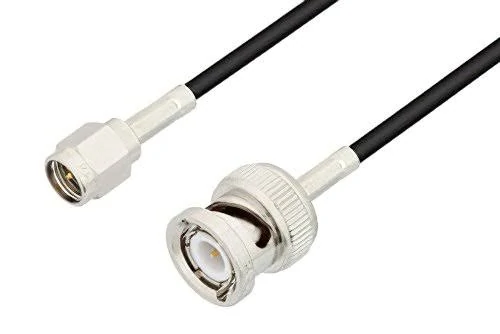
Flexible RF cable assembly with SMA male and BNC male connectors, suitable for laboratory testing, signal generators, analyzers, and production fixtures.
A rigid SMA male-to-male adapter is compact, but compact does not automatically mean mechanically safer.
If two ports are perfectly aligned, fixed in position, and mechanically supported, a rigid adapter can provide a simple direct connection. Problems start when the adapter bridges two devices that can move independently.
A small alignment error creates side loading. Instrument movement increases that force. The adapter then behaves like a lever attached to the SMA jack.
A simplified bending-moment estimate is:
- (M) is the bending moment applied to the port
- (F) is the cable weight, pull force, or side load
- (d) is the distance from the port to the point where the force acts
The formula does not replace a mechanical design analysis, but it shows why an unsupported adapter stack can damage a connector more easily than expected.
Use the following decision table before selecting the connection method.
| Installation question | If yes | If no |
| Are both ports precisely aligned and fixed? | Continue checking | Use a flexible cable |
| Will either device move during operation or maintenance? | Use a flexible cable | Continue checking |
| Will the link be disconnected frequently? | Prefer a replaceable test jumper or port saver | Continue checking |
| Is the rigid adapter mechanically supported? | It may be acceptable | Avoid the unsupported adapter |
| Is fixed geometry more important than movement tolerance? | Evaluate semi-rigid or phase-stable construction | Use a flexible jumper |
A short flexible SMA jumper cable can absorb port-position tolerance, operator handling, bench vibration, rack spacing changes, and minor routing errors. It also lets the cable weight be supported away from the instrument connector.
A rigid adapter remains useful in a designed fixture where both ports are aligned, the spacing is controlled, and the assembly is not carrying an unsupported mechanical load. For broader connector and adapter selection, see the SMA cable selection guide.
How Should a Production Jumper Differ From a Lab Test Lead?
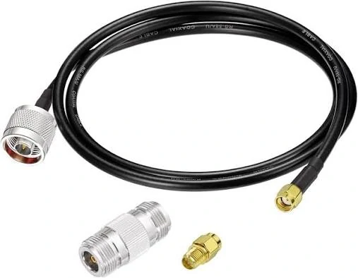
N male to SMA male coaxial cable shown with RF connector adapters for interface conversion, equipment testing, and flexible RF system integration.
A production jumper is normally selected to provide a repeatable electrical connection inside a product or test fixture. The main requirements may include correct connector ends, cable length, basic insertion loss, VSWR, flexibility, cost, and consistent assembly quality.
A test lead has a different job.
It may be connected and removed every day. It may be bent during calibration, fixture adjustment, or DUT replacement. Its loss and phase can directly affect the measured result. A cable that is acceptable for an internal RF connection may not be stable enough for measurement work.
An SMA male to male test cable may need requirements for:
- Amplitude stability during movement
- Phase stability
- Connector reconnection repeatability
- Shielding effectiveness
- Defined sweep range
- Controlled calibration plane
- Serialized VNA test data
- Mating-cycle records
- Approved routing geometry
The term “measurement-grade” has little value unless the supplier defines what was measured.
A credible specification should state the frequency range, S-parameter limits, bend condition, number of reconnection cycles, test fixture, calibration method, and permitted variation. Phrases such as “high precision,” “microwave quality,” or “premium test cable” do not establish an acceptance limit.
Decide Where the Calibration Plane Ends
The cable must be treated consistently during calibration and measurement.
In one workflow, the test cable is included during calibration. The calibration plane is moved to the far end of the cable. After calibration, the cable should remain connected and in a stable routing condition.
In another workflow, the cable remains part of the measured RF path. Its S-parameters, insertion loss, phase delay, or correction data may need to be recorded separately.
Moving, replacing, or reconnecting a cable after calibration can change the measurement condition. The effect may be small in a tolerant test and unacceptable in a phase-sensitive measurement. The procedure should define what operators are allowed to move after calibration.
Match the Coax Construction to the Cable’s Motion Profile
The cable should be selected by how it will be used, not only by its nominal impedance or outside diameter.
RG174 is compact and flexible. It can work in short, protected fixture links where routing space is limited and the loss budget is not demanding. It is less attractive for a frequently handled bench lead when the assembly needs stronger shielding, lower loss, or better dimensional stability.
RG316 is a common choice for short laboratory and production connections. It offers a small diameter, flexible routing, and heat-resistant dielectric construction. An RG316 SMA male to male cable is often practical for bench equipment changes, compact fixtures, and short RF links.
That does not make every RG316 assembly equivalent. Braid coverage, conductor construction, jacket material, connector termination, and manufacturing control vary by supplier.
Double-shielded flexible coax can improve isolation in a noisy fixture or near digital switching circuitry. The trade-offs are usually greater diameter, higher stiffness, larger termination hardware, and tighter routing requirements.
Semi-rigid and semi-flexible constructions are more suitable when geometry must remain controlled. They can be useful in fixed fixtures, calibration assemblies, multichannel comparison paths, and phase-sensitive links. They are not ideal for a cable that operators repeatedly bend or reposition.
| Cable construction | Relative flexibility | Typical strength | Main limitation | Suitable role |
| RG174 | High | Compact routing | Higher loss and limited handling stability | Short protected fixture link |
| RG316 | High | General bench and production use | Performance varies by construction and termination | Flexible SMA RF jumper cable |
| Double-shielded flexible coax | Medium | Better shielding potential | Larger and stiffer | Noisy fixtures and controlled routing |
| Semi-rigid or semi-flexible | Low | Stable retained geometry | Poor fit for repeated movement | Fixed and phase-sensitive fixtures |
Exact attenuation, bend radius, temperature rating, and shielding data should come from the actual cable manufacturer’s datasheet. A generic RG designation should not be treated as a complete performance guarantee.
For a broader comparison of coax families and general assembly requirements, refer to the RF cable assemblies guide.
How Much Error Can the Jumper Add to an RF Measurement?
Insertion loss is only one part of the problem.
A cable may have acceptable initial S21 and still create unstable measurements after it is moved. Connector mismatch, calibration residual error, reconnection variation, fixture repeatability, temperature change, and instrument noise may all contribute.
A simplified engineering uncertainty budget can be written as:
- is calibration residual uncertainty
- represents mismatch and contact variation
- s movement- or temperature-related cable variation
- is reconnection repeatability
- is variation introduced by the test fixture
This RSS calculation is suitable for an initial engineering budget when the terms are treated as approximately independent. It is not a substitute for a formal laboratory uncertainty analysis.
Measure the Change, Not Only the First Sweep
The first trace establishes the baseline. Qualification should also measure how the result changes.
Useful test states include:
- Initial connection
- After five reconnections
- After ten reconnections
- Cable moved to the left
- Cable moved to the right
- Cable placed at the minimum approved bend
- Cable installed in the final fixture route
The limits must match the application. A general production fixture may care mainly about insertion-loss and return-loss change. A phased or multichannel system may need phase and electrical-delay limits as well.
A cable that passes a single straight-state sweep has not yet demonstrated that it will behave consistently during real operation.
Set the Passband at the Cable’s Final Routed Shape
RF acceptance should cover the full operating band, not one convenient spot frequency.
The purchase or test specification should define:
- Sweep start and stop frequencies
- Number or spacing of test points
- Maximum insertion loss
- Maximum VSWR or minimum return loss
- Phase or delay requirement
- Test power level when relevant
- Calibration plane
- Cable routing condition
A cable may pass while lying straight and change after it is installed against a fixture wall. The final route can introduce a tighter bend near the connector, jacket compression, cable twisting, or strain at the termination.
At minimum, compare these states:
- Cable lying straight
- Cable in the approved service loop
- Cable at the minimum allowed bend
- Cable installed in the production fixture
The first bend should not begin directly at the connector tail. Define a no-bend zone, minimum straight section, strain-relief length, clamp distance, and allowed cable-exit angle.
Record the bend radius, bend angle, bend location, connector orientation, and support points. A routing photo is often more useful than a vague note stating that the cable was “bent during test.”
Detailed loss planning for longer SMA links is covered in the SMA RF cable length and loss planning guide.
Which Connector Geometry Reduces Port Damage?
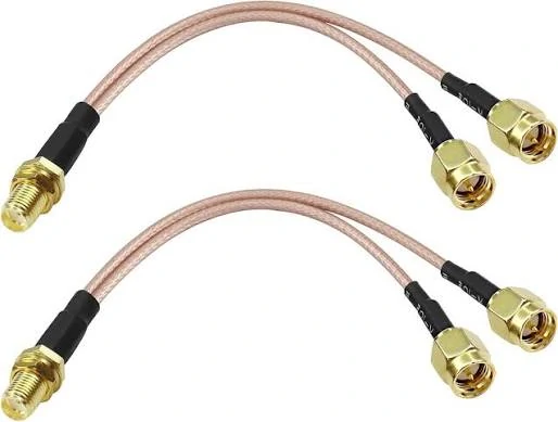
Flexible RF splitter cable assembly featuring an SMA female connector and two SMA male connectors for signal routing, test fixtures, and compact RF systems.
Straight SMA ends work well when the cable can leave the port axially and enough clearance is available. They are common on open test benches, front-panel instruments, and fixtures with generous cable-routing space.
A right-angle connector can reduce the need for a tight bend in shallow racks or compact fixtures. The assembly drawing must define the exit direction. Ordering “one right-angle end” without specifying its orientation can result in a cable that points toward a wall, door, or adjacent connector.
Controlled mating torque also requires enough access for the correct tool. Confirm:
- Coupling-nut style
- Wrench-flat dimensions
- Torque-wrench clearance
- Connector-body holding method
- Anti-rotation requirement
- Adjacent-port spacing
The cable weight should be supported by a clamp, rack tie point, service-loop bracket, or fixture support. The instrument SMA jack should not carry the full weight or repeated pulling force of the cable.
A port saver can be left on an expensive instrument connector when the port experiences frequent mating. The saver then becomes part of the RF path and should be included during calibration and test-path evaluation.
How Short Should the Link Be Without Restricting Movement?
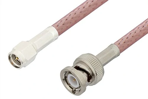
Flexible SMA male to BNC male RF cable assembly using RG316-style coax for compact routing, instrument connections, and test fixture applications.
The shortest electrical path is not always the best physical length.
A cable that barely reaches may pull the ports out of alignment, restrict instrument movement, or force an immediate bend behind the connector. A cable that is unnecessarily long may move during measurement, tangle with other leads, or create an uncontrolled phase change.
Start with the actual routed centerline rather than the straight-line distance between ports.
Include:
- Connector-body clearance
- Bend arcs
- Cable-support route
- Door or drawer movement
- Calibration access
- Maintenance space
- Operator service allowance
- Manufacturing tolerance
A practical worksheet uses:
The drawing should also state how length is measured. “500 mm cable” is ambiguous unless the reference is defined. Depending on the product, length may be measured mating-plane to mating-plane, connector-end to connector-end, or by exposed cable length.
Physical length and electrical length are not identical.
For an ordinary single-channel jumper, physical length is often the main production control. For phase-matched assemblies, specify electrical delay or phase tracking rather than assuming that equal cut length creates equal RF behavior.
When Do Several Cables Need Phase or Amplitude Matching?
Matched cable sets are used when channel-to-channel differences matter.
Applications include:
- Multichannel receivers
- Antenna-array testing
- Power-divider output comparison
- Phase-comparison measurements
- Synchronized RF systems
- Gain tracking between parallel channels
Two cables with the same nominal type and physical length can still differ because of dielectric variation, termination geometry, connector construction, and actual electrical length.
An estimated phase difference caused by electrical-length variation can be expressed as:
- is the estimated phase difference
- is operating frequency
- is the electrical-path difference
- is propagation velocity in the cable
The higher the frequency, the more phase error a given length difference creates.
A matched-set requirement should define:
- Frequency range
- Maximum amplitude difference
- Maximum phase difference
- Temperature condition
- Approved routing state
- Reconnection condition
- Test method
- Set identification
Keep the cables together through production and service. Use a set number, individual serial numbers, End A and End B labels, stored S-parameter files, calibration date, and an approved replacement policy.
Replacing only one cable in a matched set may invalidate the original tracking data.
How Should First Articles Be Qualified Before Volume Orders?
The first article should prove more than appearance and continuity.
Start with interface identity and workmanship:
- Correct standard SMA male ends
- Correct center pins
- Correct cable family
- Acceptable plating condition
- Secure ferrule or termination
- Correct heat-shrink position
- Accurate labels
- No visible jacket damage
- No loose connector body
Then verify the finished length, connector orientation, wrench access, body dimensions, fixture fit, bend clearance, and cable exit.
Electrical qualification may include DC continuity, center-to-shield isolation, full-band S21, S11, S22, movement stability, reconnection repeatability, phase, and delay.
| Test item | Test condition | Measurement | Acceptance basis | Required record |
| Interface inspection | Unmated | Visual and dimensional | Approved drawing | Inspection photos |
| Finished length | Free state | Defined mechanical reference | Drawing tolerance | Inspection sheet |
| Continuity | Straight and gently flexed | DC resistance | Project limit | Test log |
| Insertion loss | Full frequency band | S21 | RFQ limit | VNA file |
| Return loss | Full frequency band | S11 and S22 | RFQ limit | VNA file |
| Movement stability | Defined bend sequence | ΔS21 and Δphase | Project limit | Comparison plot |
| Reconnection repeatability | Defined cycle count | Maximum delta | Project limit | Cycle report |
| Pull retention | Approved fixture | Force | Mechanical limit | Test report |
| Label verification | Final assembly | Visual | Correct P/N and serial | Inspection record |
The IEC 61169-1 general RF connector specification can provide background on common connector test and measurement methods. Project-specific limits still need to be defined in the drawing or RFQ.
Prototype approval and production sampling should be separated.
Prototype assemblies may receive full dimensional, mechanical, and RF testing. The first production lot may use an increased RF sample size. Once the process is stable, inspection can move to a risk-based sampling plan. Measurement-critical cables may still require 100% serialized RF data.
How Do You Turn the Use Case Into a Complete Purchase Specification?
A complete part description should identify the two interfaces, cable type, length, frequency, and test requirement.
A useful format is:
End A + End B + Cable Type + Length + Frequency + Test Requirement
Example:
SMA Male Straight to SMA Male Straight, RG316, 500 mm, DC–6 GHz, Full-Band VNA Tested
The RFQ should not stop there.
Electrical requirements
Specify:
- 50-ohm impedance
- Start and stop frequency
- Maximum insertion loss
- Maximum VSWR or minimum return loss
- Phase or delay limit
- Shielding requirement
- Power level
- Calibration role
- Movement-stability limit
Mechanical requirements
Specify:
- Straight or right-angle connectors
- Right-angle exit orientation
- Cable family and outside diameter
- Finished length
- Length reference
- Length tolerance
- Minimum bend radius
- No-bend zone
- Strain relief
- Expected mating cycles
Documentation requirements
Request only the documents the application actually needs:
- Certificate of conformity
- Dimensional inspection report
- VNA plot
- Touchstone file
- Cable serial number
- Lot number
- Test frequency range
- Calibration-plane description
- Test fixture description
- Approved routing photograph
A practical RFQ can be written as:
End A: SMA male straight End B: SMA male straight Cable: RG316 Impedance: 50 ohms Finished length: 500 mm Length reference: Mating plane to mating plane Frequency range: DC–6 GHz Insertion loss: Customer-defined full-band limit Return loss or VSWR: Customer-defined full-band limit Movement condition: Occasional bench movement Reconnection test: Ten defined cycles Labeling: Part number, lot number, and serial number Test data: PDF VNA plot and Touchstone file Prototype quantity: [Enter quantity] Annual quantity: [Enter quantity]
This level of detail makes quotations easier to compare. It also reduces the chance that one supplier prices a basic connectivity jumper while another prices a serialized, movement-tested RF lead.
For general cable-family loss, bend, and ordering considerations, see the SMA to SMA cable guide.
FAQ
Can the same SMA male to male cable be used before and after VNA calibration?
Yes, but the calibration procedure must define whether the cable is inside or outside the calibration plane. If it is included during calibration, moving, replacing, or reconnecting it afterward may change the original measurement condition. High-repeatability procedures normally keep the cable connected and in a controlled routing state.
Should the test cable remain connected after a two-port calibration?
Keeping the cable connected usually improves repeatability because the connector contact and bend condition remain unchanged. When disconnection is unavoidable, the allowable measurement change should be established through a controlled reconnection test rather than assumed.
Is low VSWR enough if the cable phase changes when it moves?
No. Low VSWR indicates acceptable reflection behavior, but it does not prove stable insertion loss, phase, or electrical delay during movement. Phase-sensitive and multichannel systems need additional stability limits.
Can an RG316 male-to-male cable replace a semi-rigid fixture link?
It can replace one in a flexible, loss-tolerant connection, but the two constructions are not automatically equivalent. A fixed fixture may depend on retained geometry and phase stability that a frequently moved RG316 cable does not provide. Test the replacement in the final route before approving it.
Why does the measurement change after reconnecting the same cable?
The change may come from connector seating, mating torque, interface contamination, port wear, contact position, cable routing, or a shifted calibration plane. Controlled torque, clean interfaces, routing control, and reconnection testing help identify the normal variation.
When should a port saver remain attached to the instrument?
A port saver is useful when an instrument connector is expensive or experiences frequent mating. Once installed, it becomes part of the RF path. Include it during calibration and account for its loss, mismatch, and repeatability.
Do matched cable sets need equal physical length or equal electrical delay?
Phase-sensitive systems care more about electrical delay and full-band phase tracking. Equal physical length is only a starting control. Final matching should be verified by measurement and preserved through serial-numbered set management.
Specify the Cable as Part of the Test System
An SMA male to male coax cable used between two female ports is easy to describe badly.
The words “SMA male both ends, RG316, 500 mm” may be enough for a basic jumper. They do not define a stable RF test lead.
A measurement link should also describe how the cable will move, where the calibration plane is located, what frequency band must be swept, how much change is allowed after bending or reconnection, and what test data must accompany the assembly.
The most useful RFQ is not the longest one. It is the one that separates real requirements from assumptions.
For a TEJTE custom cable review, provide the two port interfaces, cable construction, finished length, frequency range, routing condition, insertion-loss or return-loss target, reconnection requirement, and required test records. That information allows the supplier to determine whether a general SMA jumper is sufficient or whether the application needs a more controlled test-cable construction.
