
A cable assembly can pass continuity testing and still fail when it enters an RF system.
This happens more often than many buyers expect. The connector mates correctly, the cable length looks right, and the first sample may work on a bench test. The problem appears later when the assembly is installed inside equipment, operated near the upper frequency limit, or compared against another batch from production.
A multimeter can confirm that the conductor is connected. It cannot tell whether the impedance is correct, whether energy is being reflected, or whether the signal loss becomes unacceptable at a specific frequency.
That is where RF testing becomes necessary.
For RF cables, connectors, adapters, attenuators, splitters, couplers, and termination components, engineers usually need more than a simple electrical check. They need measurement data that explains how the complete signal path behaves.
A practical RF validation process normally combines impedance analysis, reflection measurement, transmission measurement, and comparison against defined acceptance limits.
How Does RF Testing Verify a Complete Signal Path?
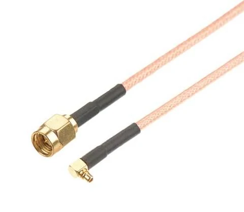
RF cable assembly featuring SMA and MMCX connectors with flexible coaxial cable. The assembly is commonly used in wireless communication equipment, RF modules, antenna systems, and laboratory test setups.
Evaluate the entire RF chain instead of a single component
This is especially important for applications using 50 ohm systems, where even small impedance changes can affect reflected energy.
For engineers purchasing RF assemblies, the specification should describe the complete configuration:
| Item | Information to Confirm |
| Connector Interface | SMA, N, BNC, TNC, 2.92 mm, 3.5 mm, etc. |
| Cable Type | RG316, RG174, RG58, low-loss cable, semi-rigid cable |
| Frequency Range | Operating frequency and required test band |
| Length | Cable length including tolerance |
| Measurement Requirement | S11, S21, VSWR, insertion loss |
| Application | Prototype, production, test fixture, field equipment |
A supplier providing only “cable passed continuity” is not providing enough information for many RF applications.
Understand why continuity testing is not enough for RF systems
Continuity testing is useful, but it answers only a basic question:
Is there an electrical connection?
A continuity test can detect:
- open circuit
- short circuit
- incorrect wiring
- obvious assembly damage
However, RF signals behave differently from low-frequency electrical signals.
At higher frequencies, engineers also need to evaluate:
- impedance
- reflection
- insertion loss
- frequency response
- phase behavior
A connector pin can have perfect DC contact but still create an RF discontinuity.
For example, an incorrectly positioned center contact inside an RF connector may slightly change the transmission structure. The assembly may pass a multimeter test, but a VNA measurement can show increased reflection near the operating frequency.
This is why RF buyers should separate two inspection levels:
| Inspection Method | What It Confirms | Limitation |
| Continuity Test | Basic electrical connection | Cannot verify RF behavior |
| Visual Inspection | Assembly appearance and mechanical issues | Cannot measure signal quality |
| VNA Measurement | Reflection and transmission characteristics | Requires proper calibration and setup |
| Production Test Record | Repeatability between batches | Depends on defined standards |
In practical sourcing, continuity testing is a first inspection step, not a final RF acceptance method.
Identify when RF testing becomes necessary
Not every RF product requires the same measurement depth.
A short cable used in a low-frequency application may only require basic inspection. A precision microwave assembly used for measurement equipment requires much tighter validation.
RF testing becomes more important in situations such as:
- production inspection
- customer qualification
- prototype development
- troubleshooting unexpected signal loss
- incoming inspection from suppliers
- high-frequency test equipment assembly
A practical example is a custom RF cable assembly.
A buyer may order an SMA cable based on connector type and length. However, the final result depends on several combined factors:
- whether the connector matches the cable diameter
- whether the termination process is correct
- whether the cable bend radius was exceeded
- whether the operating frequency is close to the assembly limit
The connector name alone does not define the RF performance.
For this reason, experienced RF buyers usually specify not only the mechanical requirements but also the validation target:
- operating frequency
- acceptable VSWR
- maximum insertion loss
- required test report
- sample approval method
- production inspection frequency
How Do Engineers Use a Network Analyzer for RF Validation?
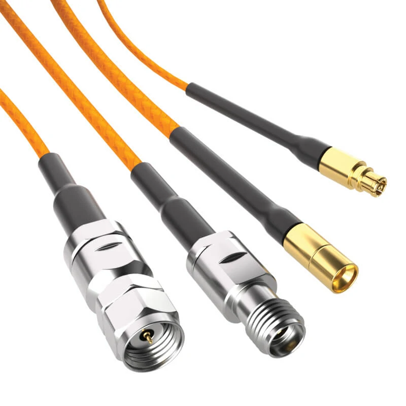
A high-frequency RF cable assembly with different connector interfaces used for RF testing and signal validation. VNA measurement can evaluate S parameters, insertion loss, and reflection characteristics to ensure reliable performance in RF systems.
Understand what a VNA measures in an RF system
A network analyzer, especially a vector network analyzer (VNA), is one of the primary instruments used for RF measurement.
Unlike a simple electrical tester, a VNA evaluates how RF energy behaves when it travels through a device under test.
Typical measurements include:
- S parameters
- reflection characteristics
- transmission characteristics
- phase response
For passive RF components, these measurements help engineers determine whether the device performs as expected across the required frequency range.
A VNA does not simply answer “connected or disconnected.”
It answers questions such as:
- How much signal is reflected?
- How much signal is transmitted?
- Where does loss increase?
- At which frequency does the behavior change?
These answers are important when validating:
- coaxial cable assemblies
- RF adapters
- attenuators
- splitters
- couplers
- RF loads
How Do Engineers Use a Network Analyzer for RF Validation?
Match the measurement setup with the device under test
A VNA measurement is only meaningful when the test setup matches the actual RF application.
One reason different laboratories sometimes obtain different results from the same RF component is not necessarily product variation. The difference may come from the measurement environment.
Before starting an RF measurement, engineers normally confirm:
- connector type
- frequency range
- calibration method
- reference plane
- test cable condition
- adapter configuration
- connection repeatability
For example, measuring a 3.5 mm connector assembly with a test setup designed for a lower-frequency connector system can introduce additional uncertainty. Similarly, a worn calibration kit or damaged test cable can affect the measurement before the device under test is even connected.
A VNA does not remove the need for good test practices.
The instrument measures what it sees at the reference plane. If losses, reflections, or mechanical errors exist before that point, the final result may include those effects.
Avoid confusing instrument capability with measurement accuracy
A common assumption is that a higher-frequency VNA automatically produces better measurement results.
The instrument bandwidth matters, but it is only one part of the measurement chain.
Actual RF measurement accuracy also depends on:
- calibration quality
- test cable performance
- adapter quality
- connector condition
- mechanical repeatability
- operator technique
For example, a VNA capable of measuring up to 50 GHz cannot compensate for a damaged adapter or an incorrectly assembled connector.
This becomes especially important in microwave applications.
At higher frequencies, small mechanical differences become more visible:
- center pin misalignment
- connector face contamination
- incorrect tightening torque
- excessive adapter stacking
- cable movement during testing
A stable measurement process requires controlling these variables.
For production environments, repeatability is often more valuable than a single impressive test result.
A supplier testing one sample under ideal conditions does not automatically prove that every production batch will behave the same way. The measurement method, acceptance standard, and traceability process are equally important.
How Do S Parameters Explain RF Component Behavior?
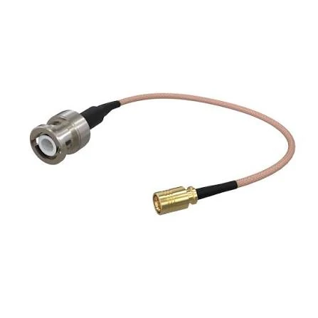
BNC to SMA adapter cable used for RF measurement and equipment connection. Proper connector matching, impedance control, and RF testing help reduce signal reflection and transmission loss.
Read S11 when you need to understand reflection
S parameters are commonly used to describe how RF energy interacts with a device.
For a two-port network, the most commonly discussed parameters are:
- S11 — input reflection
- S21 — forward transmission
S11 describes how much energy is reflected back toward the source.
A high reflection value often indicates problems such as:
- impedance mismatch
- connector transition issues
- incorrect termination
- damaged RF structure
In practical RF systems, reflection is not only a theoretical value.
Compare S11 and S21 before approving an RF component
During product validation, engineers should avoid approving components based on a single measurement.
Consider an RF cable assembly:
| Measurement | Possible Result | Meaning |
| S11 | Good | Impedance matching is acceptable |
| S21 | Poor | Excessive signal loss exists |
| S11 | Poor | Reflection issue may exist |
| S21 | Good | Transmission loss may be acceptable |
A cable may transmit a signal but still have a mismatch problem.
Another cable may have acceptable matching but excessive attenuation at higher frequencies.
The correct evaluation depends on the application requirement.
For example:
- A short internal connection may tolerate slightly higher loss.
- A VNA test cable requires tighter control.
- A high-frequency microwave assembly may require both low reflection and low insertion loss.
This is why RF specifications should define the measurement target before production begins.
How Can You Interpret Reflection and Matching Results?
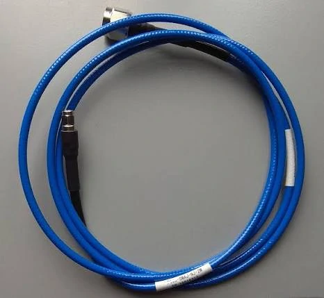
Blue low-loss RF cable assembly designed for signal measurement and microwave applications. Cable construction, connector quality, and frequency range all influence RF performance during testing.
Connect reflection coefficient with real RF problems
Reflection coefficient is useful because it directly describes the relationship between incident energy and reflected energy.
However, engineers usually do not evaluate reflection coefficient alone.
In practical testing, the same behavior is often converted into:
- VSWR
- Return Loss
These formats are easier to compare with product specifications.
For example, a customer may not request “reflection coefficient below a certain value.” Instead, they may specify:
- VSWR ≤ 1.5
- Return Loss ≥ 14 dB
- Insertion Loss ≤ specific dB value
The measurement format depends on industry practice and application requirements.
How Can You Interpret Reflection and Matching Results?
Relate VSWR and return loss without repeating separate guides
In RF testing, engineers often use VSWR and return loss to describe the same reflection behavior from different perspectives.
VSWR provides a ratio-based view of impedance matching.
Return Loss expresses reflected energy using decibels.
For example:
| Reflection Result | Engineering Meaning |
| Low VSWR | Better impedance matching |
| High Return Loss | Less reflected signal |
| Large Reflection Coefficient | Greater mismatch risk |
| Unstable measurement curve | Possible assembly or setup issue |
However, a good VSWR result alone does not guarantee that an RF assembly is suitable for every application.
Engineers still need to consider:
- operating frequency
- insertion loss
- cable length
- power level
- environmental conditions
- connector durability
A cable assembly used for a short laboratory connection and a cable installed inside outdoor communication equipment may require completely different acceptance standards.
Find the difference between acceptable mismatch and a real failure
Not every mismatch represents a product failure.
RF systems always have some level of loss and reflection. The key question is whether the measured result remains within the application requirement.
A practical evaluation should consider:
- frequency range
- application purpose
- specification limits
- measurement method
- repeatability
For example, an RF adapter may show slightly different results when measured at 1 GHz and 18 GHz.
The same component can be acceptable in one system but unsuitable in another.
This is why RF engineers normally define the measurement condition before judging the result.
A useful acceptance document should include:
- test frequency range
- equipment model
- calibration method
- connector interface
- cable configuration
- pass/fail criteria
Without these conditions, two test reports may appear different even when both products are within specification.
How Should You Test RF Components Before Integration?
Validate passive components with the right measurements
Different RF components require different validation methods.
Testing every product with the same measurement approach can waste time or miss important problems.
A practical test method depends on the function of the component.
| Component | Main Test Focus | Typical Measurement |
| Cable Assembly | Signal transmission and matching | S11 / S21 |
| RF Attenuator | Attenuation accuracy and matching | Attenuation / VSWR |
| RF Splitter | Distribution balance and loss | Insertion Loss / Isolation |
| RF Coupler | Sampling accuracy | Coupling / Directivity |
| RF Load / Terminator | Signal absorption | Reflection Measurement |
For example:
An RF attenuator may show acceptable VSWR but incorrect attenuation value.
A splitter may have acceptable input matching but poor isolation between output ports.
A terminator may look mechanically correct but create reflection if the internal resistance is inaccurate.
The test method should follow the electrical purpose of the component.
Separate product failure from measurement setup problems
When an RF test result is abnormal, replacing the product immediately is not always the correct first step.
A structured troubleshooting process helps identify the actual cause.
Only after the measurement setup is confirmed should the product itself be considered the source of the issue.
This approach is especially useful during customer complaints or supplier quality investigations.
A product that fails one test does not always mean the product design is wrong.
Record test conditions before comparing results
RF data without test conditions has limited value.
A professional RF test report should record the environment where the measurement was performed.
Important fields include:
| Field | Example |
| Product Model | SMA Cable Assembly |
| Test Equipment | Vector Network Analyzer |
| Calibration Method | SOLT / Other calibration method |
| Frequency Range | DC–6 GHz |
| S11 Result | Reflection curve |
| S21 Result | Transmission curve |
| VSWR | Measured value |
| Return Loss | dB value |
| Test Date | Production record |
| Result | Pass / Fail |
This information allows engineers, suppliers, and customers to compare results correctly.
It also improves production traceability when the same product is manufactured over multiple batches.
RF Testing Decision Tree: Select the Right Measurement Method
When engineers receive a new RF component, the following decision process can help determine the correct validation method.
| Question | Recommended Measurement |
| Need reflection information? | S11 / VSWR / Return Loss |
| Need transmission information? | S21 / Insertion Loss |
| Need attenuation verification? | RF Attenuator Test |
| Need signal distribution verification? | Splitter Test |
| Need sampling performance verification? | Coupler Test |
| Need terminal matching verification? | RF Load / Terminator Test |
This decision method prevents unnecessary testing and helps buyers communicate requirements more clearly with suppliers.
How Do You Build a Reliable RF Test Setup?
Keep impedance consistent through the complete measurement chain
A reliable RF test setup starts with impedance control.
For most commercial RF systems, the standard impedance is 50 ohms.
The complete path should maintain consistency:
Connector → Cable → Adapter → DUT → Load
Every transition can introduce additional reflection.
For example, combining multiple adapters to connect two instruments may solve a mechanical problem, but each additional interface creates another possible RF discontinuity.
Reducing unnecessary transitions usually improves measurement repeatability.
Minimize unnecessary adapters and connection points
Adapters are useful when different connector standards need to be connected.
However, they should not become a permanent substitute for the correct assembly.
Each additional connection point may introduce:
- additional insertion loss
- reflection changes
- mechanical tolerance variation
A direct cable assembly is often preferred over a chain of multiple adapters when the application requires stable RF performance.
This is especially important for:
- VNA test cables
- microwave measurement systems
- high-frequency modules
- precision RF fixtures
Control mechanical factors during RF measurement
RF performance is affected by mechanical details.
During testing, engineers should control:
- connector torque
- connector cleanliness
- cable bending
- fixture position
- repeated mating cycles
A connector tightened too much may damage the interface.
A connector tightened too loosely may create inconsistent contact.
A cable repeatedly bent beyond its recommended radius may change the internal structure and affect measured results.
RF testing is not only about instruments. It is also about controlling the physical conditions around the measurement.
How Can RF Testing Improve Production Quality?
Use RF testing during incoming inspection and mass production
RF testing is valuable not only in laboratories.
It also supports production quality control.For example, a buyer requesting an RF cable assembly should specify
A standard low-frequency cable may require basic inspection.
A precision microwave assembly may require complete RF measurement records.
Define acceptance limits before testing begins
A common mistake is measuring first and deciding acceptance criteria afterward.
The acceptance standard should be defined before production.
How Do You Choose the Right RF Test Method for Different Applications?
Select testing methods for communication equipment
Communication systems often include antennas, wireless modules, and RF front-end circuits.
Typical validation focuses on:
- impedance matching
- signal loss
- connector reliability
- frequency response
For these applications, RF testing helps confirm that the assembly performs correctly inside the final device.
Select testing methods for laboratory measurement systems
Laboratory environments usually require stricter repeatability.
Applications may include:
- VNA test cables
- spectrum analyzer connections
- signal generator paths
- calibration fixtures
In these cases, connector quality, cable stability, and measurement repeatability become major factors.
Select testing methods for custom RF assemblies
Custom assemblies require more communication between supplier and customer.
Important information includes:
- interface type
- frequency range
- cable structure
- length tolerance
- test standard
- acceptance criteria
A good RF supplier should understand not only how to manufacture the assembly but also how the customer plans to verify it.
How Can RF Testing Improve Production Quality?
Use RF testing during incoming inspection and mass production
RF testing is valuable not only in laboratories.
It also supports production quality control.
A standard low-frequency cable may require basic inspection.
A precision microwave assembly may require complete RF measurement records.
Define acceptance limits before testing begins
A common mistake is measuring first and deciding acceptance criteria afterward.
The acceptance standard should be defined before production.
How Do You Choose the Right RF Test Method for Different Applications?
Select testing methods for communication equipment
Communication systems often include antennas, wireless modules, and RF front-end circuits.
Typical validation focuses on:
- impedance matching
- signal loss
- connector reliability
- frequency response
For these applications, RF testing helps confirm that the assembly performs correctly inside the final device.
Select testing methods for laboratory measurement systems
Laboratory environments usually require stricter repeatability.
Applications may include:
- VNA test cables
- spectrum analyzer connections
- signal generator paths
- calibration fixtures
In these cases, connector quality, cable stability, and measurement repeatability become major factors.
Select testing methods for custom RF assemblies
Custom assemblies require more communication between supplier and customer.
Important information includes:
- interface type
- frequency range
- cable structure
- length tolerance
- test standard
- acceptance criteria
A good RF supplier should understand not only how to manufacture the assembly but also how the customer plans to verify it.
FAQ
Why can two laboratories measure different RF results on the same component?
Different measurement environments can produce different results even when testing the same RF component.
Common reasons include:
- different VNA calibration methods
- different reference planes
- different test cables
- different adapters
- connector torque variation
- connector cleanliness
- fixture differences
RF measurement results are only meaningful when the test conditions are clearly recorded.
A professional RF test report should include the equipment, calibration method, frequency range, connection method, and acceptance criteria.
What is the difference between S11 and S21 measurement?
S11 and S21 describe different aspects of RF behavior.
Both measurements may be needed before approving an RF assembly.
Can a better RF component fix a poor test setup?
No.
A measurement system is only as reliable as the complete test chain.
A structured troubleshooting process should verify the test environment first, then evaluate the device under test.
Why should RF test conditions be recorded with measurement results?
Because RF data without conditions cannot be compared reliably.
When should an RF supplier provide S parameter data?
S parameter data is especially useful for products where signal integrity directly affects system performance.
Typical applications include:
- high-frequency cable assemblies
- precision RF test cables
- microwave components
- RF adapters
- production validation projects
- customer qualification samples
For standard low-risk applications, basic inspection may be sufficient.
For higher-frequency or tighter-tolerance applications, S11 and S21 data provide a clearer view of how the component behaves inside the RF system.
