
A cable can have the correct SMA connectors, pass continuity testing, and still be the wrong part for the RF path.
This often happens with an SMA male to female cable ordered only by connector gender and approximate length. The 30 cm sample works on an open bench, so purchasing changes the production order to 3 m for easier installation. The connectors still mate. The impedance is still listed as 50 ohms. Yet the longer assembly now consumes more of the link budget, forms a tighter bend near the enclosure, and places additional load on the device port.
Cable length is not a packaging detail. With an RG316 assembly, it affects attenuation, routing, connector strain, test results, and whether a published 0–6 GHz rating is useful in the real installation.
This guide explains how to select a practical length from 8 cm to 10 m without treating every available SKU as electrically equivalent.
Which Existing Ports Require a Male-to-Female Cable?
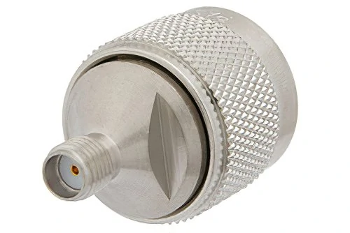
This image shows a compact SMA connector interface installed on a large knurled metal component. It supports the need to inspect the mating threads and center contact before selecting an SMA male-to-female cable or an additional RF adapter.
Start with the interfaces already installed in the system.A standard SMA male-to-female cable is commonly used when the device has an SMA female port and the antenna, jumper, test fixture, or panel component at the other end already has an SMA male interface.
A typical path looks like this:
Device With SMA Female Port→ SMA Male Cable End→ RG316 Cable→ SMA Female Cable End→ Existing SMA Male Antenna or Jumper That arrangement is useful for relocating an antenna, moving an RF test point, protecting a PCB-mounted connector, or adding distance between a radio module and an external cable.
It is not the correct arrangement when both fixed ports are SMA female. In that case, a male-to-male cable is normally required. When both fixed interfaces are male, the system may need a female-to-female assembly or another carefully reviewed coupling arrangement.
The connector gender also says nothing about RF signal direction. A passive cable assembly normally carries RF energy in either direction. “Male” and “female” describe mating geometry, not source and load.
SMA Cable-End Selector
| Existing Port A | Existing Port B | Recommended Cable |
| SMA female | SMA male | SMA male to female |
| SMA female | SMA female | SMA male to male |
| SMA male | SMA male | SMA female to female or reviewed coupler solution |
| RP-SMA present | Any SMA port | Stop and verify polarity |
| Unknown | Unknown | Inspect thread and center contact |
Do not rely on a product title such as “SMA extension cable.” Write both connector ends into the BOM.
For a broader comparison of connector-end combinations, see the SMA-to-SMA cable guide.
How Can You Confirm Standard SMA Before Ordering?
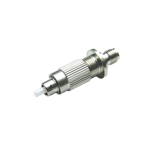
Close-up of a compact threaded connector adapter featuring a knurled metal body and a protruding ceramic ferrule. The image illustrates why connector families should be confirmed from interface drawings and front-facing photographs rather than identified only by their threaded appearance.
SMA and RP-SMA components can look deceptively similar in side-view product photos. Thread position alone is not enough.
For standard SMA:
- SMA male normally has external threads and a center pin.
- SMA female normally has internal threads and a center socket.
Reverse-polarity SMA changes the center-contact arrangement while retaining a similar threaded interface. This creates an expensive sourcing trap: the threads may begin to engage even though the center contacts cannot mate correctly.
Two pins can collide. Two sockets can leave the signal path open. A buyer may not discover the problem until the parts reach assembly.
Request front-facing photographs or an interface drawing whenever the polarity is not already controlled by an approved part number.
Keep the Complete Path at 50 Ohms
The phrase 50 ohm SMA cable should describe the complete RF path, not just the cable jacket.
Confirm the nominal impedance of:
- The radio or test-equipment port
- Both SMA connectors
- The RG316 cable
- The antenna or load
- Any bulkhead connector
- Any inline or right-angle adapter
A 50-ohm cable does not correct a mismatched 75-ohm component elsewhere in the path. Nor does continuity testing confirm impedance behavior.
SMA Identity Verification Card
The RP-SMA versus SMA guide provides a more detailed polarity check for buyers handling Wi-Fi and antenna products.
How Should 8 cm to 10 m Cable Lengths Be Compared?
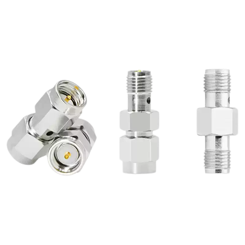
This image shows several straight SMA gender adapter configurations, including male-to-male, female-to-female, and male-to-female arrangements. It supports the recommendation to specify the correct cable-end combination in the BOM and avoid unnecessary adapter chains in an RF installation.
The shortest available assembly is not automatically the best electrical choice, and the longest assembly is not automatically the safest mechanical choice.
An 8 cm jumper may create very little cable attenuation but leave no room for connector access or a controlled bend. A 10 m assembly may solve the physical reach problem while consuming an unacceptable amount of RF margin.
A useful first step is to group the lengths by installation role.
These ranges are a planning framework rather than a universal industry standard. The correct boundary changes with frequency, acceptable insertion loss, transmitter power, receiver sensitivity, and installation geometry.
Compare Reach and RF Cost Together
For each candidate SKU, record:
- Required route length
- Connector access allowance
- Bend allowance
- Service slack
- Estimated cable attenuation
- Existing adapter count
- Expected port strain
- Maintenance access
- Whether the cable will be fixed or moved
A 50 cm assembly with two unnecessary adapters may be worse than a purpose-built 60 cm cable with the correct ends. The extra interfaces add mismatch opportunities, mechanical length, and another pair of surfaces that can loosen or become contaminated.
Define the Measurement Reference
“1 m cable” can mean several things depending on the drawing:
- Reference plane to reference plane
- Connector tip to connector tip
- End of body to end of body
- Cable-jacket length only
The difference matters most on short assemblies. On an 8 cm jumper, two connector bodies may occupy a large portion of the stated length.
Specify the measurement method and tolerance before approving production.
What Is the Maximum RG316 Length for the Loss Budget?
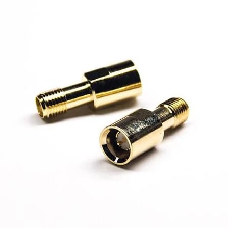
Two compact gold-plated inline RF adapters are shown from different angles. The image illustrates why cable-length calculations should include every connector transition, because additional adapters can introduce mismatch points, mechanical leverage, and extra insertion loss.
RG316 is compact, flexible, and widely used for short RF assemblies. It is not a zero-loss conductor.
Cable attenuation increases with length and normally becomes more significant as operating frequency rises. The attenuation value must come from the confirmed cable specification used in the finished assembly—not from a generic number copied from an unrelated RG316 datasheet.
The basic cable-loss calculation is:
ILcable = α(f) × L
Where:
- is estimated cable insertion loss in dB.
- is RG316 attenuation at the operating frequency in dB/m.
- is cable length in meters.
The result is only the cable contribution. The finished path also contains connector transitions and possibly other interfaces.
Extra interfaces may include:
- Inline adapters
- Panel feedthroughs
- Right-angle adapters
- Antenna adapters
- Test-fixture transitions
- Connector savers
Solve Backward From the Permitted Loss
When the maximum acceptable loss is known, calculate the longest theoretical cable length:
This is more useful than asking whether RG316 “works” at a certain frequency.
The formula can answer practical questions:
- What length stays below a 1 dB total-loss limit?
- Is a 3 m assembly acceptable at 900 MHz but unsuitable at 5.8 GHz?
- How much margin remains after including two adapters?
- At what point should the cable family change?
- Which standard SKU is the longest option that still passes?
The calculated value is not the final purchasing length. A standard SKU should be selected below the theoretical maximum so that production variation, bending, remating, and measurement uncertainty do not consume the entire margin.
Maximum Length Calculator
The Keysight paper on cable length and VNA system performance also highlights why cable length, movement, and mechanical condition matter during RF measurement.
When Does RG316 Stop Being the Right Cable?
RG316 remains a strong option when routing space, flexibility, small outer diameter, and temperature resistance matter more than minimum attenuation.
Typical applications include:
- Compact radio enclosures
- Short antenna extensions
- Internal RF module links
- Laboratory fixtures
- Panel-to-PCB connections
- Short cables that require repeated handling
The decision changes when length begins to dominate the link budget.
Review another cable family when:
- The selected length exceeds the calculated loss limit
- The operating frequency moves toward the upper end of the assembly rating
- Receive sensitivity is critical
- Several meters of routing are required
- Higher RF power is involved
- The installation is fixed and can accept a larger cable
- Outdoor feeder performance matters more than compact routing
Cable-Change Trigger Matrix
A cable substitution also changes the connector termination.
Moving from RG316 to RG58, LMR-200, or another cable requires a fresh check of:
- Cable outer diameter
- Center conductor size
- Ferrule and crimp dimensions
- Connector rear-body geometry
- Bend radius
- Jacket material
- Power rating
- Finished assembly frequency
- Pull-force requirement
An SMA connector described only by its front interface is not automatically compatible with every coaxial cable. The body, center contact, dielectric support, and ferrule must match the selected cable construction.
For a broader cable-family comparison, refer to the RG cable guide.
How Short Is Too Short for Mechanical Reliability?
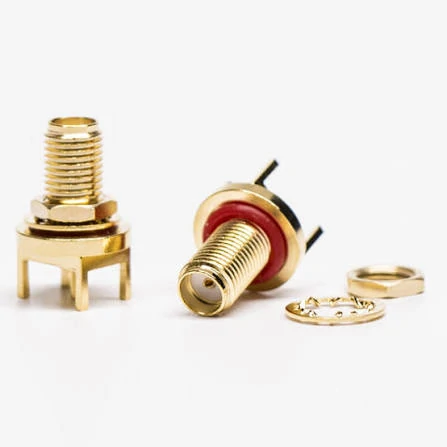
Gold-plated SMA female connectors are shown in PCB-mount and bulkhead-style configurations, together with mounting hardware. The image supports the article’s guidance to identify the installed device port before specifying the connector ends and length of an SMA extension cable.
Ordering the exact straight-line distance is a common cause of damaged RF ports.
The required length should include more than the distance between two connector faces:
Lrequired =Lroute+ Lconnector access+ Lbend allowance+ Lservice slack A cable that is too short may cause:
- Axial pull on the SMA connector
- Side loading at the PCB port
- A sharp bend immediately behind the connector
- Connector loosening during vibration
- Cable-jacket deformation
- Stress on solder joints or PCB pads
- Difficult installation and maintenance
Keep the First Bend Away From the Connector Exit
Review:
- Required straight exit length
- Minimum permitted bend radius
- Heat-shrink or boot length
- Enclosure-wall position
- Clamp location
- Wrench or finger access
- Direction of connector rotation during mating
A technically acceptable bend radius may still be wrong when it begins too close to the connector body.
Support the Cable Independently
Do not use the SMA connector as a cable clamp.
Possible strain-relief methods include:
- Nylon cable clamps
- Tie mounts
- Panel brackets
- Service loops
- Strain-relief sleeves
- Bulkhead transitions
For an external antenna connection, a panel-mounted pigtail may be safer than routing the external cable load directly into a PCB-mounted SMA port.
Mechanical Fit Worksheet
Can a 0–6 GHz Label Apply to Every Length?
The same connector type may appear on an 8 cm cable and a 10 m cable. That does not make the assemblies electrically equal.
A 0–6 GHz statement may indicate that the connector design and assembly construction are intended for use through 6 GHz. It does not mean:
- Every length has the same insertion loss
- Every SKU is low loss at 6 GHz
- Every assembly has been individually tested
- A 10 m cable preserves the same link margin as an 8 cm cable
- Connector bandwidth replaces finished-assembly verification
“Works at 6 GHz” and “meets a specified loss limit at 6 GHz” are different claims.
Treat the Complete SKU as the Rated Object
A useful specification format is:
A weak specification is:
RG316 Cable, 0–6 GHz
The weak version does not identify the assembly length, the connector interfaces, the loss limit, or the inspection method.
IEC 61169-15 defines dimensional and inspection requirements for the SMA interface. It does not replace the need to verify the complete cable assembly at its actual length. The relevant standard can be reviewed through the IEC SMA interface publication.
Frequency-Claim Approval Gate
The SMA connector frequency-range guide explains the difference between connector ratings and complete-system performance in more detail.
How Should the Finished Cable Be Verified With a VNA?
Continuity testing is useful, but it only confirms that a DC electrical path exists.
A cable can pass continuity and still have:
- Poor braid contact
- Incorrect strip dimensions
- A damaged dielectric
- Center-pin misalignment
- Excess solder
- An unstable crimp
- Impedance discontinuities
- High insertion loss near the upper band
- Poor return loss
A two-port VNA measurement is more suitable for evaluating the finished assembly.
Place the Calibration Planes at the Cable Interfaces
Record:
- VNA model
- Calibration method
- Calibration kit
- Frequency sweep
- Port adapters
- Test cables
- Connector torque
- Cable position during measurement
- Ambient condition when relevant
Unrecorded adapters between the calibration plane and test cable become part of the result. This can make a good assembly appear worse or hide repeatability problems in the fixture.
Measure S11 and S21
Typical acceptance data may include:
- Input return loss
- Output return loss, when required
- Insertion loss
- Worst frequency
- Band-edge results
- Unit-to-unit variation
- Phase data, when relevant to the application
Repeat After Remating and Controlled Flexing
A practical sequence is:
- Measure the initial assembly.
- Disconnect and reconnect both ends.
- Repeat the sweep.
- Bend the cable to a documented representative radius.
- Repeat S11 and S21.
- Compare the change.
- Inspect the connector exits if the result moves unexpectedly.
This test can expose a marginal center contact, incomplete shield termination, or mechanically unstable crimp.
SMA Cable Acceptance Standard
| Test Item | Method | Acceptance Field |
| Connector A | Visual and drawing | Correct or incorrect |
| Connector B | Visual and drawing | Correct or incorrect |
| SMA/RP-SMA polarity | Contact inspection | Pass or fail |
| Nominal impedance | Documentation | 50Ω |
| Overall length | Dimensional inspection | Target ± tolerance |
| Center continuity | DMM | Pass or fail |
| Shield continuity | DMM | Pass or fail |
| Center-to-shield isolation | Resistance test | Project limit |
| Return loss | VNA | Minimum ___ dB |
| VSWR | VNA | Maximum ___:1 |
| Insertion loss | VNA | Maximum ___ dB |
| Remating variation | Repeat sweep | Maximum change |
| Flex variation | Controlled bend | Maximum change |
| Final decision | Review | Approve or reject |
What Must the Drawing and RFQ Specify?
“SMA extension cable” is not a production-ready description.
A normalized description should include the two interfaces, cable family, impedance, length, and frequency target:
SMA Male to SMA Female Cable RG316, 50 Ohm 1,000 mm Overall Length DC–6 GHz
That still requires measurable acceptance fields.
Lock the Mechanical Definition
Specify:
- Connector A interface and polarity
- Connector B interface and polarity
- Overall length
- Length reference points
- Length tolerance
- Cable outer diameter
- Straight exit length
- Minimum bend radius
- Heat-shrink length
- Boot or strain-relief dimensions
- Cable-marker position when required
Add Electrical Limits
Record:
- Nominal impedance
- Operating frequency
- Maximum insertion loss
- Maximum VSWR or minimum return loss
- RF power requirement
- Test method
- Sampling level
- Whether a VNA report is required
- Whether test data must be linked to the production lot
Include Environmental and Packaging Requirements
Depending on the project, the RFQ may also need:
- Operating temperature
- Storage temperature
- Jacket material
- Flame-retardant requirement
- Humidity or salt-spray requirement
- Vibration requirement
- Pull-force requirement
- Mating-cycle requirement
- Individual bagging
- Dust caps
- Cable labels
- Lot traceability
When Should Another Architecture Replace the Extension Cable?
Some installations should not use a long inline RG316 extension at all.
Use a Bulkhead Pigtail to Protect the Enclosure
A panel-mounted pigtail is useful when:
- The external antenna cable will be connected repeatedly
- The enclosure should carry the mechanical load
- The PCB connector needs protection
- Vibration is present
- A sealed panel interface is required
- Internal cable routing must remain controlled
Use a Lower-Loss Feeder for Long Runs
Review a larger cable when:
- RG316 exceeds the loss budget
- Several meters are required at 5 or 6 GHz
- Receiver margin is limited
- Higher transmitter power is involved
- The installation is fixed
- A larger bend radius is acceptable
The larger cable may need a different connector series or a short transition pigtail at the equipment end.
Use a Rigid Adapter Only When Distance Is Not Required
A direct adapter may suit two adjacent ports in a controlled bench setup. It is usually a poor substitute for a flexible cable when alignment is imperfect or either device may move.
Rigid adapters can transfer torque and side load directly into the equipment connectors.
Remove Adapter Chains
Avoid paths such as:
SMA Port→ Gender Adapter→ Extension Cable→ Right-Angle Adapter→ Antenna Adapter→ Antenna A cleaner arrangement is:
SMA Port→ Purpose-Built SMA Male-to-Female Cable→ Antenna Fewer interfaces make the path easier to specify, test, install, and troubleshoot.
FAQ
Why can an 8 cm cable and a 1 m cable both be labeled for 6 GHz?
The SMA connector design may support operation through 6 GHz on both products, but the longer cable introduces more attenuation. The two assemblies therefore have different insertion-loss results even when the connector interfaces, cable family, and nominal impedance are identical. The useful specification is the measured or calculated loss of the complete length, not the connector frequency label by itself.
Can an SMA male-to-female cable carry signals in both directions?
Yes. A passive coaxial cable assembly is normally bidirectional. Male and female describe the mechanical mating interfaces. They do not define the direction of RF transmission. The system designer must separately identify the transmitter, receiver, antenna, load, or measurement-port direction.
Should the stated cable length include the connector bodies?
That depends on the drawing convention. Length may be specified from reference plane to reference plane, tip to tip, body to body, or by cable-jacket length. The difference is especially important on short 8 cm, 10 cm, or 20 cm assemblies. The purchase order and drawing should use the same reference method.
Why can a cable pass continuity but fail at 5 or 6 GHz?
A continuity test only confirms a conductive DC path. High-frequency performance also depends on impedance consistency, braid termination, dielectric condition, center-contact alignment, crimp geometry, connector mating, and cable routing. A defective assembly may show normal continuity while producing excessive insertion loss or poor return loss on a VNA.
Can a 10 m RG316 extension work if the transmitter has enough power?
More transmitter power does not recover receive-path loss, improve mismatch, remove noise, or correct a damaged link margin. It may also create power-handling or regulatory concerns. A 10 m RG316 assembly should be evaluated using the actual frequency and loss budget. A lower-loss feeder is often a more controlled solution.
When should a bulkhead pigtail replace an inline extension cable?
Use a bulkhead pigtail when the enclosure should carry external cable load, the internal PCB connector requires protection, the external antenna will be mated repeatedly, or the installation is subject to vibration. The bulkhead creates a defined mechanical boundary and allows the internal cable to be routed and clamped independently.
Does every production cable need an individual VNA report?
Not always. Precision test systems, low-margin RF paths, aerospace equipment, or high-risk programs may require individual test records. Mature high-volume assemblies may instead use approved first articles, process controls, and batch sampling. The RFQ should define the inspection level so the supplier can quote the correct test time and documentation.
Final Buying Guidance
Select the SMA interfaces first, but do not stop there.
For each SMA male to female extension cable, confirm the actual RG316 attenuation at the operating frequency, calculate the total path loss, include connector and adapter allowances, and then choose the shortest standard length that still provides safe routing and service slack.
Before releasing the order, the BOM should state:
- Standard SMA male on one end
- Standard SMA female on the other
- 50-ohm RG316 cable
- Defined overall length and tolerance
- Operating-frequency range
- Maximum insertion loss
- VSWR or return-loss limit
- Minimum bend radius
- Inspection and test method
- Packaging and labeling requirements
The available 8 cm to 10 m range gives buyers flexibility. It does not remove the need to calculate. Near the upper operating band, the cable may become the limiting part of the RF path long before the SMA interface itself does.
