SMA Female Connector Guide: Selection, Mounting & IP67 Specs
Oct 3,2025
The image shows how to verify whether a port is SMA female or RP-SMA female by checking the center contact (socket vs pin).
How do I verify I really need an SMA female (not RP-SMA)?
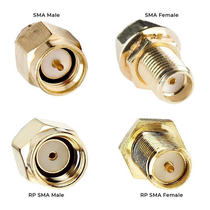
The illustration highlights why misidentifying polarity can cause Wi-Fi/IoT connectors to fail mating.
One of the first questions buyers ask is whether their device really requires an sma female connector or an RP-SMA female. At a glance, they look deceptively similar because both use external threads. The critical difference hides in the dielectric.
- SMA female → external thread + center socket (hole)
- RP-SMA female → external thread + center pin
This tiny detail determines whether your connector mates correctly. If you choose the wrong one, no amount of torque or adjustment will make the pair fit.
I’ve seen this mistake often in bulk orders for Wi-Fi routers and IoT modules. Boxes arrive at a factory floor, only for installers to realize the connectors won’t mate. A simple 10-second visual check with a magnifying glass could have saved an entire shipment from being stuck in storage.
Polarity ID by thread/pin
To stay clear of mix-ups, follow a quick three-step polarity check:
- Inspect the outer shell — external threads indicate female.
- Look at the dielectric — a socket (hole) means SMA female; a pin means RP-SMA female.
- Cross-check the datasheet. For instance, TEJTE SMA connectors always specify polarity in their mechanical drawings.
Plug-and-play pairs with SMA male
Remember, an sma male connector always mates with an SMA female. The male design uses internal threads and carries a pin, making it the standard partner in RF modules, antennas, and test instruments.
If you’re unsure, here’s a practical tip: grab a known 50 ohm SMA test cable from your kit. Try mating it with the port in question. If the connection couples smoothly without resistance or wobble, you’ve confirmed you’re dealing with a genuine SMA female.
How do I match 50 Ω vs 75 Ω and my band?
Impedance matching is the backbone of RF design. The sma female connector family comes in both 50 Ω and 75 Ω versions, and while they look identical on the outside, their applications couldn’t be more different.
- 50 Ω SMA → the standard choice for wireless communication (LTE, Wi-Fi, LoRa, 5G).
- 75 Ω SMA → mainly for broadcast video, satellite, and CATV setups.
From TEJTE’s spec sheets, many SMA connectors cover DC–18 GHz with VSWR values better than 1.2 at 6 GHz. In real-world terms, that means a stable, low-reflection connection across the frequencies most engineers care about.
Pairing with 50-ohm coax at 900/2.4/5.8 GHz
If your design involves 900 MHz cellular, 2.4 GHz Wi-Fi, or 5.8 GHz backhaul, stick with a 50 ohm sma cable such as RG316 or LMR-200. This pairing ensures efficient signal transfer and keeps link budgets healthy.
TEJTE’s stainless-steel SMA series, for example, is not only rated for high-frequency performance but also tested for RoHS compliance and outdoor IP67 sealing. That makes it practical for smart-home gateways, routers, and IoT base stations that must survive rain and dust.
Symptoms of impedance mismatch
What if you mix 50 Ω and 75 Ω by accident? The signs usually show up fast:
- Ripple on a network analyzer → increased return loss.
- Weaker antenna gain → your link budget shrinks, sometimes by several dB.
- More digital errors → packet retries, CRC failures, or noisy video streams.
I’ve seen installers dismiss a mismatch as “good enough for testing,” only to get service calls weeks later. Even temporary mismatches are risky. If you must bridge two systems, use a proper adapter — for example, TEJTE’s SMA to BNC adapter provides a safe impedance-matching path for test setups without permanently degrading the signal chain.
Should I choose straight or right-angle for my layout?
Space/strain in enclosures and racks
A straight SMA works perfectly when the cable exits freely. But when space is tight — for example, in handheld radios or compact IoT boxes — the cable may need to bend sharply right after the port. That kind of stress builds up over time and can crack the dielectric. I’ve personally opened radios with burnt traces simply because a straight connector forced RG174 into an unnatural bend.
By contrast, a right-angle SMA connector routes the cable neatly along the chassis or PCB surface. This reduces stress on the dielectric and solder joints, giving the connector a longer service life. The RF loss difference is minimal at common bands like 2.4 GHz and 5.8 GHz, so in most designs the mechanical benefit outweighs any tiny insertion loss.
When to switch to an extension cable
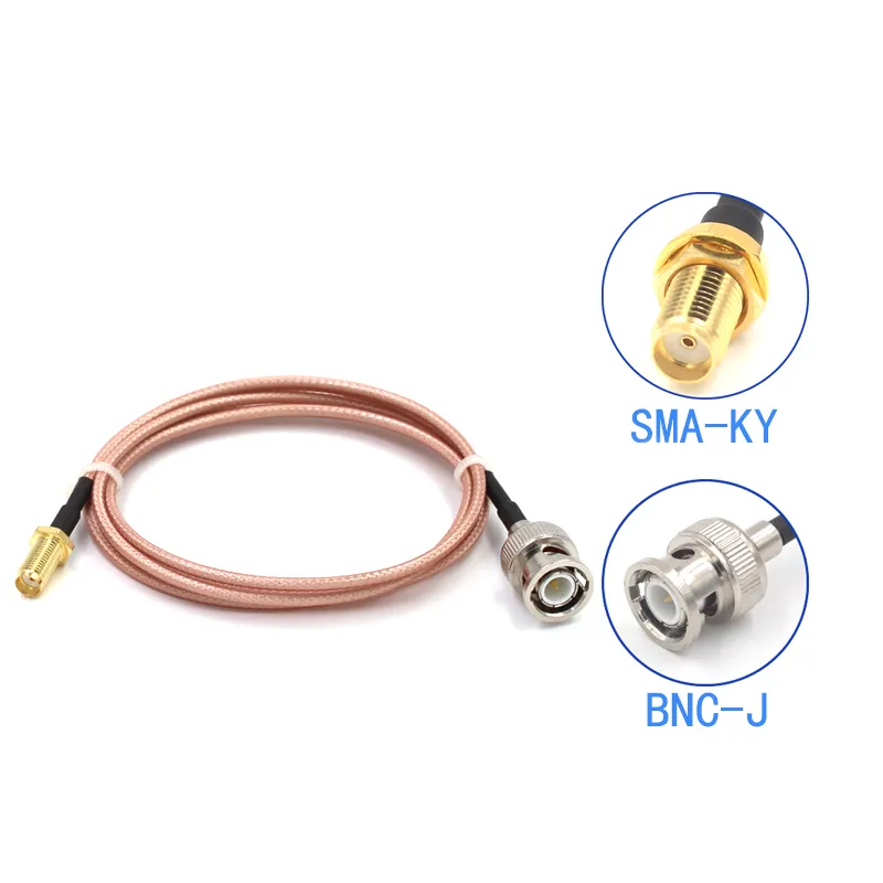
The image shows an SMA extension cable used instead of stacking adapters, offering better impedance control and reduced stress.
Sometimes neither option is ideal. If you’re working inside a crowded enclosure or need to bring the interface out to a panel, an sma extension cable makes more sense. A short RG316 jumper moves the port to where it’s accessible, without stacking adapters or forcing cable bends.
Compared to adding multiple couplers, a well-made extension introduces less cascade loss and keeps impedance under control. TEJTE’s SMA antenna extension cable guide explains how short jumpers not only simplify routing but also help with IP67 sealing when the port is exposed outdoors.
Do I need a connector, an adapter, or a jumper instead?
Using SMA adapters (M-F, to BNC) wisely
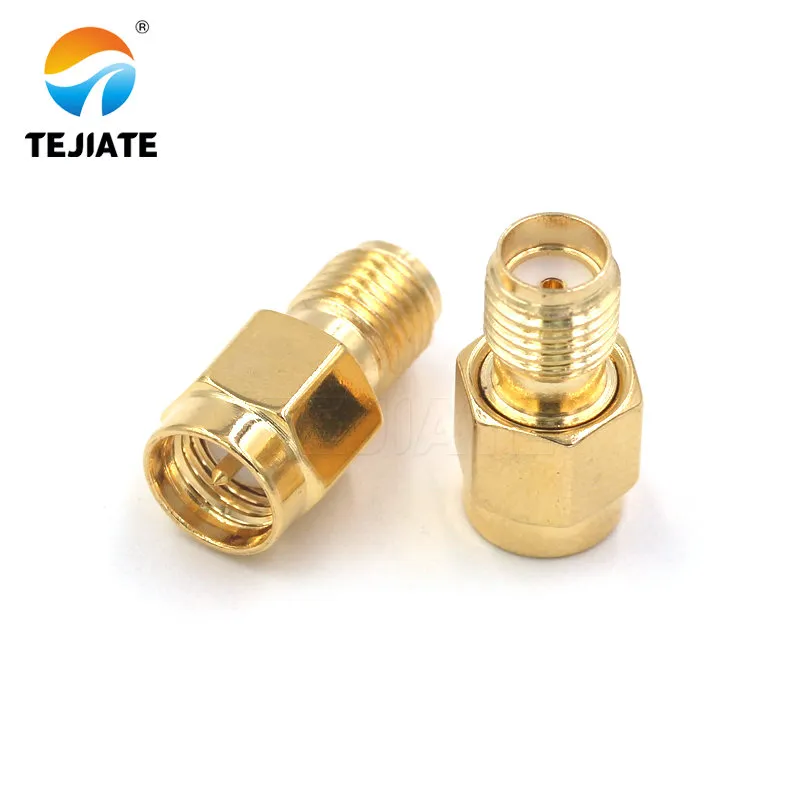
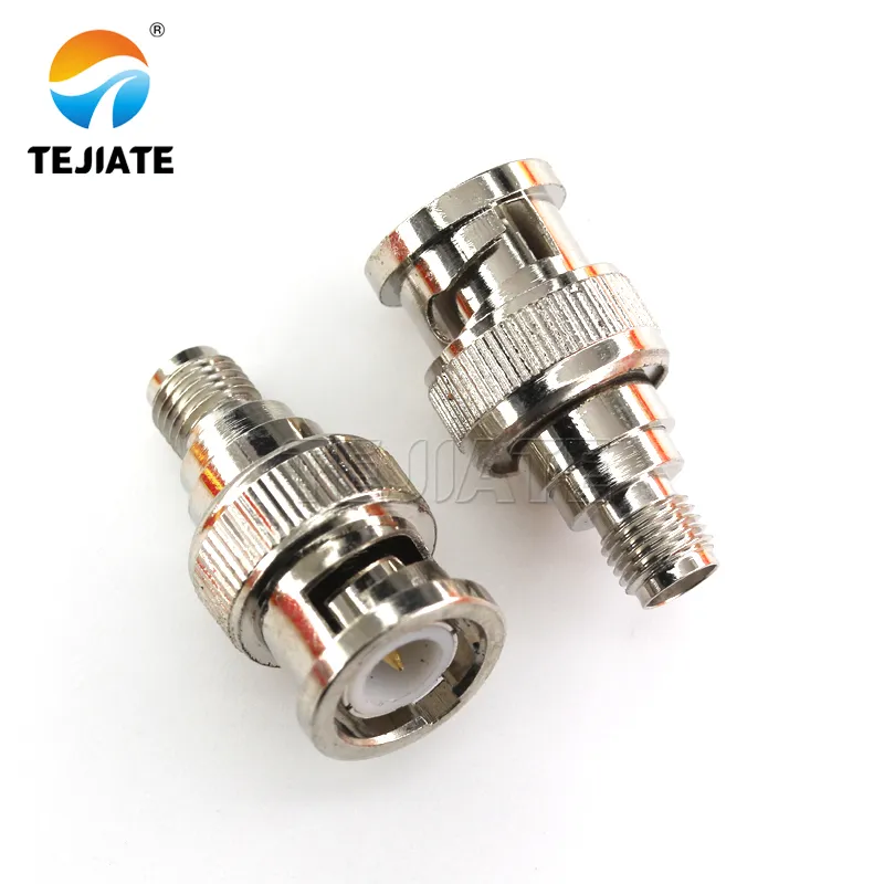
Adapters are quick problem-solvers. An sma male to female adapter lets you correct a gender mismatch without rewiring. Similarly, an sma to bnc adapter bridges modern SMA-based radios to older lab gear still using BNC.
That said, every adapter comes with a trade-off. Even high-quality parts introduce a small insertion loss — TEJTE’s testing shows values as low as ≤0.15 dB at 6 GHz — and repeated use can loosen the mechanical fit. For temporary setups, that’s acceptable. For permanent installations, try to keep adapter count to a minimum.
If you’d like to see how different adapters are applied in real cases, TEJTE’s RF adapter catalog includes both straight and right-angle types designed for lab and field use.
Short jumpers to reduce cascade loss
The comparison illustrates that a short SMA jumper outperforms two or three stacked adapters in both durability and electrical performance.
The image shows a right-angle SMA female jack, useful in handheld radios and IoT boxes where straight connectors would force cable bending.
The image shows a waterproof inline SMA female-to-female adapter with sealing cap, ensuring IP67 performance for outdoor antennas and CPE.
I’ve done this myself on test benches — swapping three adapters for one short jumper instantly cleaned up the VSWR trace on the analyzer. The improvement was obvious.
As TEJTE notes in their blog on SMA jumper assemblies, short jumpers not only control impedance better but also ease cable routing in tight enclosures. The rule of thumb is simple:
- Use connectors when the connection is permanent.
- Use adapters sparingly and intentionally.
- Use jumpers whenever more than one adapter would otherwise be required.
How do I mount PCB/bulkhead/antenna SMA female correctly?
PCB keep-outs and reflow window
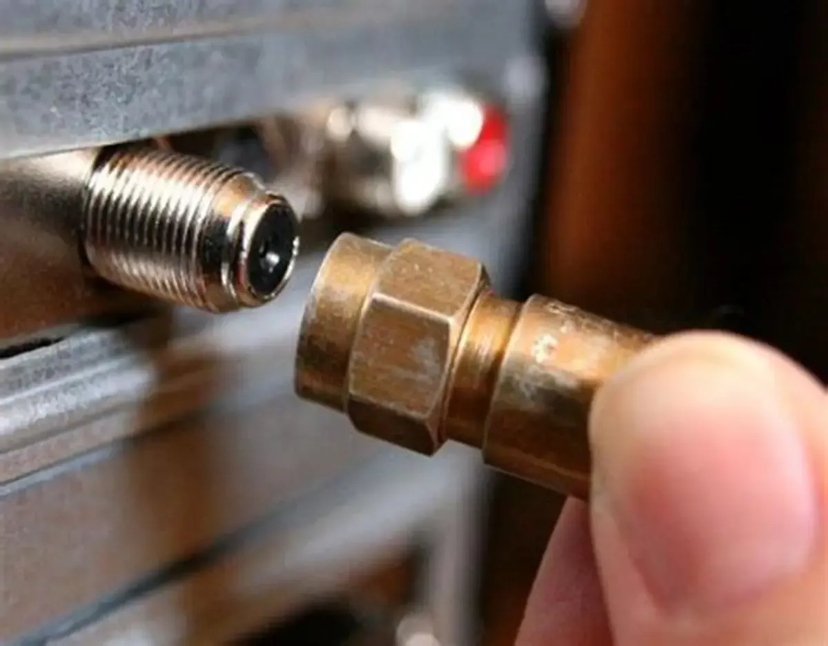
Bulkhead designs are more forgiving, yet cutout accuracy still matters. Most sma female bulkhead connectors require a 6.2–6.5 mm hole. Too loose, and the O-ring won’t seal; too tight, and you risk damaging the plating during installation. Always compress the silicone O-ring evenly for reliable IP67 sealing.
Another detail many forget: grounding. The threaded barrel must bond to chassis ground. If it floats, EMI leakage and coupling issues show up, especially above 2.4 GHz. I’ve seen field failures traced back to this oversight more than once.
These mounting details may feel like small things, but they often decide whether a connector lasts 500+ cycles or fails within months. Paying attention at this stage avoids expensive rework later.
What torque and materials should I specify?
Torque vs Material Table
| Material | Recommended Torque (N·m) | Cycle Life (mating cycles) | Wrench Size (mm) |
|---|---|---|---|
| Brass, gold-plated | 0.45 – 0.56 | ≥500 | 8 |
| Stainless steel | 0.79 – 0.90 | ≥1000 | 8 |
Notes from the field
- Too little torque → higher contact resistance, unstable VSWR.
- Too much torque → stripped 1/4–36 threads or a cracked PTFE dielectric.
- Always use an 8 mm torque wrench; relying on “finger feel” is risky.
I’ve seen engineers tighten SMA connectors “by feel,” assuming experience is enough. The outcome? Loose connections that drift in performance tests or, worse, a cracked dielectric after repeated cycling. A $50 torque wrench is far cheaper than replacing dozens of failed connectors in a deployed system.
For more context, TEJTE’s SMA male connector guide also emphasizes torque as a critical spec, right alongside plating material and dielectric choice. It’s a reminder that mechanical details often matter as much as the RF specs printed in a datasheet.
How do I crimp/solder tails to pass QC?
Crimp/Solder Spec Card
| Step / Parameter | Spec (mm/N) | Pass Criteria |
|---|---|---|
| Jacket strip length | 6.0 ± 0.3 | Within tolerance |
| Braid strip length | 3.5 ± 0.2 | No stray strands |
| Dielectric strip length | 2.0 ± 0.1 | Center pin fully seated |
| Conductor exposure | 1.0 ± 0.05 | Smooth, concentric |
| Hex crimp height (RG316) | 1.37 - 1.47 | Matches crimp gauge window |
| Minimum pull strength | ≥ 45 N | No slip at threshold |
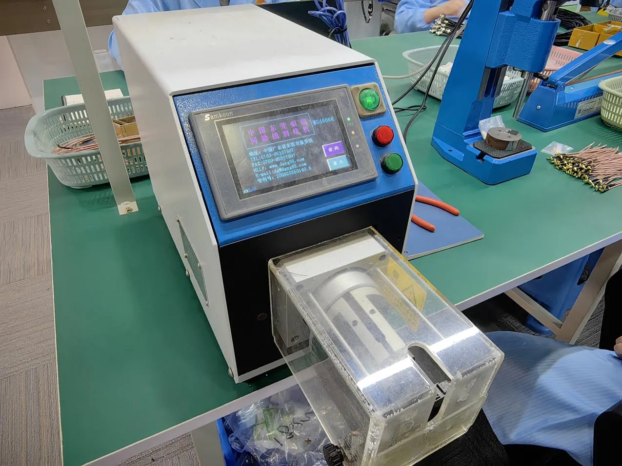
The image shows SMA female crimping with automatic tooling, following strip length and pull-force specs to pass QC.
Tooling and sampling plan
Use a calibrated hex crimp tool with locator dies. Don’t skip the step of checking against a go/no-go gauge. For batch quality, an AQL sampling plan works well—for example, one destructive pull test per 200 assemblies.
From personal experience: a single bad crimp can ruin hours of RF testing. I’ve seen entire production runs delayed because one operator used worn-out crimp dies, raising VSWR above acceptable limits. TEJTE’s RF cable assembly guide explains why consistent tooling matters just as much as following strip dimensions.
The bottom line? Treat crimping and soldering as precision steps, not afterthoughts. Get those right, and most SMA assemblies will pass QC on the first attempt.
How do I protect against outdoor/IP67 and corrosion?
Stainless steel vs brass gold-plated
TEJTE offers both brass-gold and stainless-steel SMA jacks. Brass is lightweight and cost-effective, ideal for controlled environments. Stainless steel, on the other hand, brings extra durability: it withstands torque values of 0.79–0.90 N·m, endures up to 1000 mating cycles, and resists corrosion in salt fog testing. In coastal or industrial deployments, stainless quickly pays for itself.
I’ve worked with teams who tried to cut costs by using brass connectors outdoors. Six months later, the plating was flaking, and the connectors seized from corrosion. Replacing them cost far more than choosing stainless from the start.
Waterproofing strategy: O-ring + cap + panel seal
A proper outdoor bulkhead SMA uses a silicone O-ring compressed evenly against the panel surface. Pair that with a protective waterproof cap when the port isn’t active. Finally, route the coax with a small drip loop so water doesn’t track straight into the connector.
Skipping even one of these steps can undo the IP67 rating. I’ve seen field units pass the lab’s salt-spray test yet fail outdoors simply because the installer forgot the O-ring. For a practical example, TEJTE’s SMA antenna extension cable guide shows how proper sealing and cable routing extend service life in harsh environments.
In short: for outdoor projects, think beyond the connector itself. It’s the combination of material, torque, and sealing practices that determines whether the assembly lasts years—or just a season.
What specs must I submit before ordering, and how do I accept parts fast?
Spec checklist before order
When preparing an RFQ, specify:
- Polarity (SMA vs RP-SMA)
- Gender (female vs male)
- Angle (straight vs right-angle)
- Impedance (50 Ω or 75 Ω)
- Frequency band (e.g., 2.4 GHz Wi-Fi, 5G sub-6 GHz)
- Material & plating (brass-gold, stainless steel)
- Packaging (bulk bag, tape-and-reel)
- Compliance (RoHS, REACH)
- Quantity (MOQ: often 100 pcs per bag in TEJTE’s supply chain)
I’ve seen buyers skip details like plating or compliance, only to realize later their connectors weren’t RoHS-certified—forcing costly rework. A 30-second checklist upfront prevents weeks of back-and-forth later.
For reference, TEJTE’s SMA connector catalog lists all these fields directly in the drawings, making it easier to copy into your purchase order.
IQC checklist — 5-minute incoming inspection
| Category | What to Check | Method |
|---|---|---|
| Visual | Threads, plating, dielectric quality | Loupe / naked eye |
| Dimensional | Thread gauge, cutout fit (Ø6.2-6.5 mm) | Plug gauge, caliper |
| Electrical | Continuity, insulation ≥5000 MΩ, VSWR | Multimeter, analyzer |
| Mechanical | Pull ≥45 N, torque check | Force gauge, wrench |
With these four quick checks, you’ll catch 90% of issues: eccentric pins, plating flakes, oversized holes, or crimps out of spec.
From my own experience on production floors, the fastest way to avoid headaches is to train IQC staff to use a torque wrench and pull gauge right at receiving. TEJTE’s inspection guidelines highlight exactly this approach—fast, simple, and effective.
FAQ
How do I connect RG316 coax to an SMA female bulkhead without failing pull-test?
The key is preparation. Strip the jacket, braid, and dielectric to the exact dimensions: 6.0 mm, 3.5 mm, and 2.0 mm. Crimp the ferrule at a height of 1.37–1.47 mm using a calibrated tool. During the pull test, don’t let the panel take the force—support the bulkhead body with a wrench so the load goes into the crimp. TEJTE’s guide on SMA pigtails and RG316 walks through these steps in detail.
What torque should I use for brass-gold vs stainless SMA female jacks?
For brass-gold SMA connectors, tighten to 0.45–0.56 N·m. Stainless types need more—0.79–0.90 N·m. Both use an 8 mm wrench. Don’t rely on finger-tightening; it’s almost always too loose. I’ve seen technicians “snug it by feel,” only to discover rising VSWR during testing. A simple torque wrench prevents that headache.
How do I tell SMA female from RP-SMA female at a glance?
Look at the dielectric. A socket (hole) means SMA female. A pin means RP-SMA female. Both have external threads, which is why so many people confuse them. When in doubt, check the datasheet—TEJTE’s SMA basics blog has clear diagrams to help.
When is a right-angle SMA female better than using a straight jack plus a bend?
If your cable exits the port and immediately needs to bend, a sma right angle connector is the safer choice. It relieves stress on the dielectric and solder joints. Forcing a sharp bend with a straight connector may look fine at first, but over time it can crack insulation or even lift PCB traces.
Can I mate a 50-ohm SMA female to a 75-ohm BNC system temporarily?
You can, but expect performance to drop. Reflections increase, gain drops, and in digital links you’ll see more errors. It’s fine for quick bench checks, but don’t run a live system that way. Use a proper sma to bnc adapter designed for impedance bridging—TEJTE lists these in their RF adapter series.
How long does an SMA female last in high-cycle applications?
It depends on material. Brass-gold versions last around 500 cycles, while stainless steel types can exceed 1000. Signs of wear include loose thread engagement and higher VSWR. If you’re designing for test labs or frequent connect/disconnect cycles, stainless is the safer investment.
Should I use a coupler or a short jumper between a panel jack and equipment?
Go with a sma jumper cable. While couplers stack up insertion loss and mechanical play, a short jumper maintains impedance and relieves stress. On my own benches, replacing two couplers with a 15 cm jumper instantly improved the return loss curve. TEJTE’s adapter cable series shows practical jumper options that balance flexibility with performance.
Conclusion
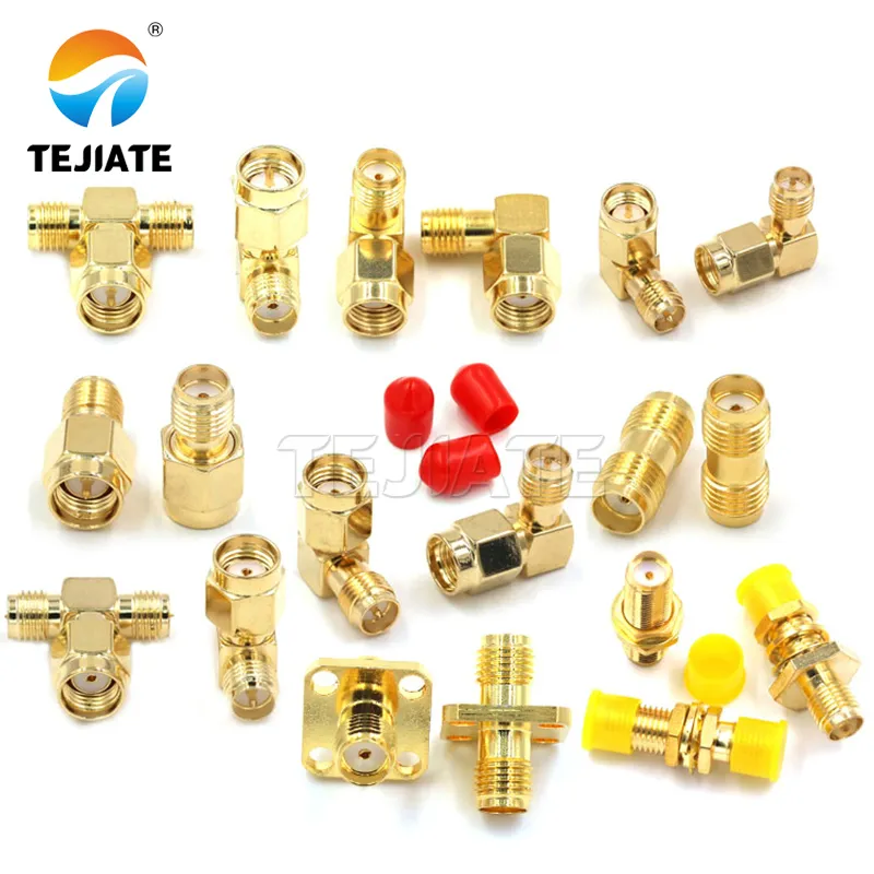
The image summarizes SMA female use in PCBs, bulkheads, extension cables, and outdoor IP67 systems, emphasizing reliability in RF links.
The sma female connector may look small, but it plays a big role in system reliability. From correctly identifying polarity versus RP-SMA, to matching 50 Ω impedance across 2.4/5.8 GHz bands, to applying the proper torque, each step matters. Even a minor oversight—like forgetting an O-ring or forcing a sharp cable bend—can shorten service life dramatically.
For indoor layouts, the choice between straight and right-angle connectors comes down to space and strain relief. Outdoors, an IP67-rated bulkhead with stainless housing and O-ring seal ensures resistance against water and corrosion. And during assembly, following proper strip lengths, crimp dimensions, and QC checks keeps rejection rates low and performance stable.
At TEJTE, our SMA portfolio covers PCB connectors, bulkhead types, extension cables, and adapters for both lab and field applications. The parameters highlighted here—DC–18 GHz bandwidth, ≤0.15 dB insertion loss, 500–1000 mating cycles, RoHS/REACH compliance—are backed by internal test reports and strict IQC inspections. On top of that, we maintain ample stock and offer customized solutions, from plating variations to cable assemblies built to your drawings.
If you’re planning your next RF project, use this article as a selection and acceptance checklist. And when you’re ready to specify or customize, explore TEJTE’s SMA female connector catalog and our RF connector blog library for practical data and real-world guidance.
In RF systems, the smallest details often decide success or failure. Choosing the right sma female connector isn’t just about ticking boxes—it’s about confidence in every connection you build.
Bonfon Office Building, Longgang District, Shenzhen City, Guangdong Province, China

A China-based OEM/ODM RF communications supplier
Table of Contents
Owning your OEM/ODM/Private Label for Electronic Devices andComponents is now easier than ever.
