SMA Extension Cable: Length, Loss & Outdoor Routing
Oct 29,2025
Preface
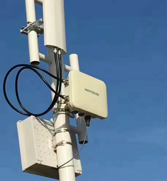
The image likely depicts a typical application scenario, such as connecting an indoor router or 4G/5G gateway to an outdoor antenna via an SMA extension cable, emphasizing the design goal of preserving signal integrity while ensuring mechanical reliability. It may include elements of TEJTE's precision-machined SMA connectors to minimize insertion loss and VSWR impact.
In wireless systems, a few decibels can decide whether your link runs clean or constantly retries. That’s why an SMA extension cable isn’t just a convenience—it’s an RF decision. Each added meter brings insertion loss, impedance shifts, and extra mated pairs that can nudge your VSWR off spec. TEJTE’s precision-machined SMA-KE/KHD bulkhead connectors, rated DC–6 GHz and tested < 0.15 dB insertion loss per pair, are designed to minimize that penalty.
Whether you’re extending a router’s antenna, linking a 4G/5G gateway to a roof-mounted panel, or routing a MIMO pair through an IP67 enclosure, the goal is always the same: preserve signal while staying mechanically sound. Let’s see when extension beats adapters, how long you can run before loss hurts throughput, and what happens if you mix SMA and RP-SMA ports.
Should you use an SMA extension cable or stack adapters?
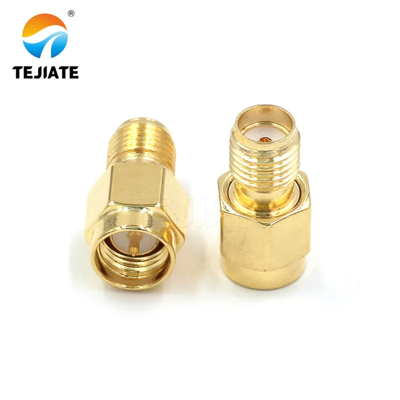
This image visually demonstrates the "adapter stacking" solution described in the document. It likely shows two or more SMA-to-SMA adapters (e.g., barrel or right-angle) connected in series, illustrating the potential risks of this approach: each adapter adds ≈ 0.1–0.3 dB loss and introduces additional points of contact resistance and mechanical failure, with performance degradation being more pronounced at high frequencies (e.g., 6 GHz).
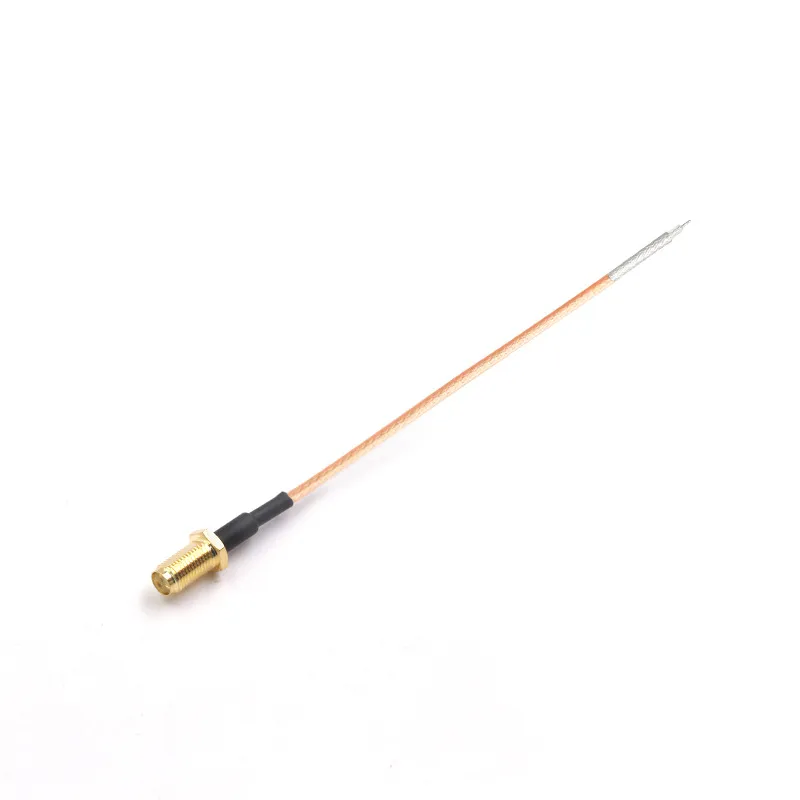
This image demonstrates the recommended "one continuous extension" solution. It likely features a close-up of a TEJTE pre-terminated assembly, including SMA connectors and cable (e.g., RG316), emphasizing its low VSWR (<1.2), high durability (500 cycles), and superior reliability and lower loss compared to adapter stacks.
Every engineer’s been tempted to stack a couple of SMA-to-SMA adapters to reach that last centimeter. It feels quick—but electrically it’s risky. Each adapter pair adds ≈ 0.1–0.3 dB loss and introduces another mating surface where contact resistance (≤ 5 mΩ typ. for TEJTE SMA-KE) can drift over time. Two extra interfaces might not kill a 2.4 GHz link, but at 6 GHz you could lose more than 1 dB before the signal even hits the antenna.
A short RG316 jumper often wins here. Its typical attenuation is ≈ 1.46 dB/m @ 2.4 GHz and 2.34 dB/m @ 6 GHz—small enough that a 0.5 m lead costs less loss than a two-adapter stack. Fewer interfaces also mean fewer mechanical failures; every added thread pair is another point that can loosen under vibration.
TEJTE offers factory-terminated extension assemblies (e.g., SMA male to female RG316 1 m) that combine low VSWR (< 1.2) with 500-cycle durability—far more reliable than field-stacked adapters. If you need a right-angle turn instead, see our related discussion on the Right-Angle SMA Adapter: Clearance, Loss & Strain Relief.
Rule of thumb: one continuous extension is almost always better than multiple adapters—both electrically and mechanically.
How long can an SMA extension be before loss kills throughput?
| Cable Type | Attenuation @ 2.4 GHz (dB/m) | Attenuation @ 6 GHz (dB/m) | Min Bend Radius | Notes |
|---|---|---|---|---|
| RG316 cable | 1.46 | 2.34 | 15 mm | High flexibility (PTFE insulation, 150 °C) |
| RG58 cable | 0.25 | 0.45 | 50 mm | Balanced for medium runs, PVC jacket ‑20 ~ 70 °C |
| LMR-240 cable | 0.16 | 0.27 | 61 mm loaded / 30 mm static | Low-loss foam-PE core for outdoor routing ‑20 ~ 80 °C |
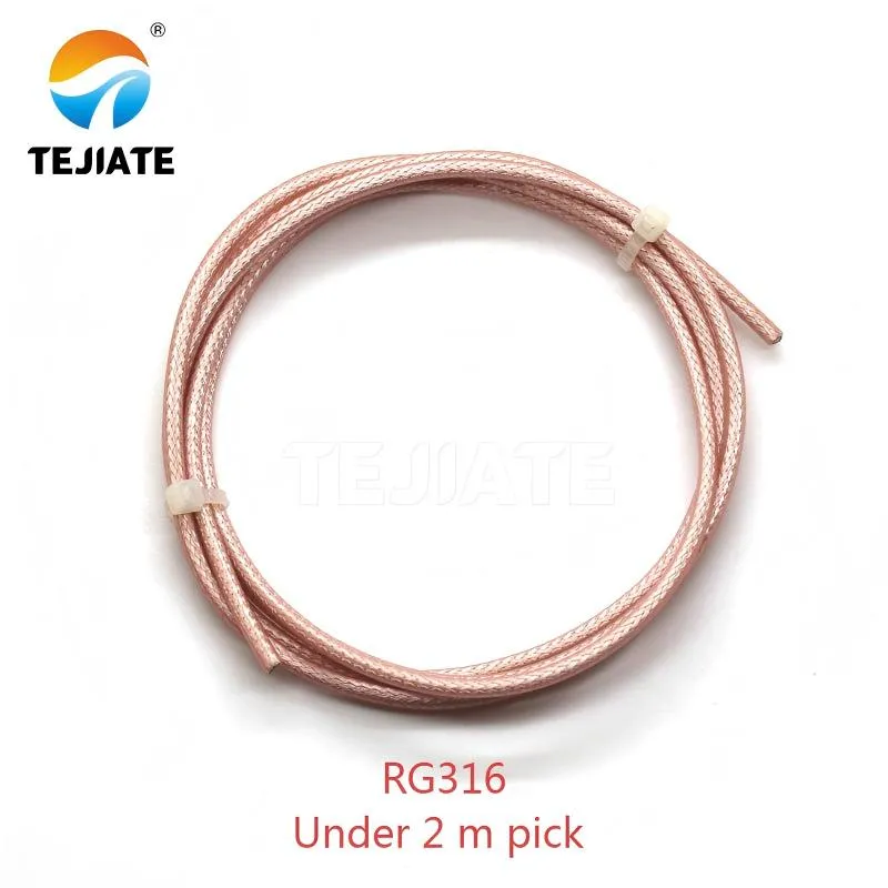
This graphic or product image aims to reinforce the recommendation in the document - "Under 2 m, pick RG316". It likely demonstrates the flexibility of RG316 cable, its silver-plated copper braid, or wiring examples in high-density equipment, emphasizing its irreplaceability in short-distance, high-frequency (despite higher loss) applications.
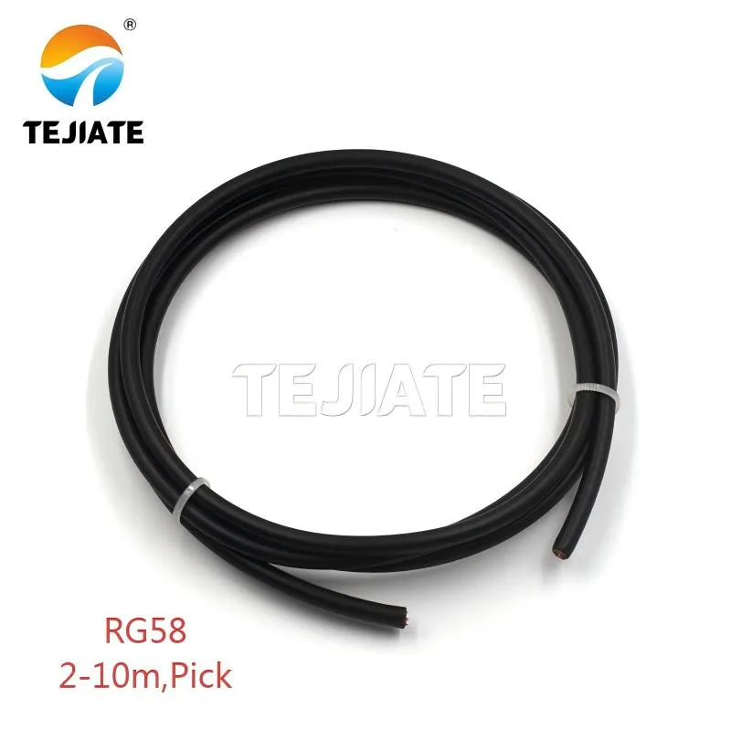
This image likely presents the relatively robust PVC jacket (5mm OD) of RG58 cable and its typical application environments, such as general indoor wiring or connections between equipment where high flexibility is not critical, visually conveying its "general-purpose" positioning.
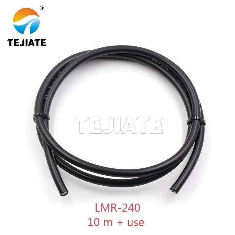
This image aims to show the robust appearance, thicker outer diameter (6.1mm) of LMR-240 cable, and its application examples in outdoor environments (e.g., rooftops, antenna masts), reinforcing its positioning as a long-distance, low-loss solution.
Suppose your 5 GHz router outputs 20 dBm and your antenna adds 5 dBi gain.
- With a 2 m RG316 run (≈ 4.7 dB loss total including two connectors), EIRP drops to 20.3 dBm—still acceptable indoors.
- Stretch that to 10 m of RG58 (≈ 4.5 dB loss) and you maintain similar performance.
- But 25 ft of RG316 (~12 dB loss) will cut throughput by half at 6 GHz.
For outdoor mounts or long roof runs, move to LMR-240, whose loss is less than half that of RG58 at the same length. The difference between 2.34 dB/m and 0.27 dB/m sounds small until you multiply by distance—then it’s the difference between a strong link and a dead SSID.
TEJTE’s LMR-240 assemblies use bare-copper inner conductor and double shield (aluminum foil + tinned-copper braid, 128×0.12 mm) for low EMI and superior UV resistance, ideal for rooftop and tower routing.
Can you mix SMA connector with RP-SMA connector safely on your router?
It’s a common mistake: the router has RP-SMA female ports, you grab a standard SMA male lead, and they thread perfectly—but no signal passes. The problem is polarity. An SMA male has a center pin; an RP-SMA female also has a pin. When joined, they short the signal path or leave it open.
Before ordering, inspect the center interface: pin vs hole tells the story. If your device has RP-SMA female ports (pin present), you need an RP-SMA male on the cable (no pin). Mixing these without adapters creates open circuits and mysterious RSSI drops.
For rugged installs or enclosures, you may prefer transitioning to an N-type bulkhead connector—its larger thread and O-ring seal simplify panel mounting and maintain IP67 integrity. TEJTE’s N-type to SMA bulkhead series is rated for 335 V working voltage and 1,000 V RMS withstand, matching the SMA-KE/KHD spec.
When mixing connectors is unavoidable, limit the count to one transition and re-check VSWR (< 1.1 typ.). Otherwise, even a small polarity mismatch can make a perfectly tuned 6 GHz chain behave like a detuned radio.
What cable should you pick for bend radius, heat, and outdoor routing?
Choosing the right SMA extension cable is a trade-off between flexibility, loss, and environment. Indoors, engineers usually favor RG316, a 2.5 mm FEP-jacketed coax that bends easily around compact router housings. It tolerates up to 150 °C and a 15 mm bend radius, so it’s perfect for IoT gateways or MIMO test fixtures. The cost is attenuation: about 1.46 dB/m at 2.4 GHz and 2.34 dB/m at 6 GHz.
For medium runs or mild outdoor exposure, RG58 provides a balance—PVC jacket, 50 Ω impedance, and roughly 0.45 dB/m loss at 6 GHz. It’s tough enough for internal cabinet routing but not ideal under UV or rain. Once a cable leaves the enclosure, switch to LMR-240, the workhorse of outdoor RF. Its foam-PE dielectric and double-shield (laminated aluminum + tinned-copper braid 128 × 0.12 mm) keep attenuation to ≈ 0.27 dB/m @ 6 GHz and ensure 90 dB shielding.
Routing near heat sources or on rooftops requires attention to mechanical strain. Always form a drip loop below the bulkhead to prevent water ingress, and use cable ties or anti-rotation clamps rated for UV. For long vertical masts, secure every 0.5 m to reduce connector torque stress. More field guidance appears in TEJTE’s LMR-240: Loss, Bend & Outdoor Routing post.
Will the extension break your IP seal or torque spec?
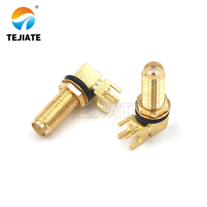
This image details the key components for ensuring the SMA extension cable maintains an IP67 rating when installed through a panel. It likely clearly shows the connector's brass gold-plated housing, PTFE insulator, and the silicone O-ring and locking nut used for compression sealing, emphasizing the importance of correct torque (≈ 0.56 N·m) for maintaining good contact resistance and preventing dielectric distortion.
Once the cable passes a panel, your RF performance is only as good as the sealing around it. TEJTE’s SMA-KE/KHD bulkhead connectors include a silicone-rubber O-ring (Grade 6146) and brass-gold-plated body rated for 335 V working voltage and 1000 V RMS withstand. When tightened correctly, the nut compresses the O-ring to maintain IP67 without distorting the dielectric.
Proper torque is crucial—around 0.56 N·m (5 in-lb) for standard SMA. Too loose and contact resistance rises; too tight and the PTFE insulator can creep, shifting pin height (± 0.05 mm tolerance). After every installation, visually confirm that the gold-plated pin sits flush with the mating plane. If it’s recessed, you risk intermittent VSWR spikes.
Heat-shrink boots or silicone sealing sleeves can reinforce the junction for long-term outdoor use. On rooftops or tower boxes, pair the bulkhead with a booted LMR-240 jumper—its 6.1 mm PVC jacket handles –20 ~ 80 °C swings while keeping moisture out. You can explore related waterproofing methods in TEJTE’s IP67 Connector: O-ring Sealing, Bulkhead Install & Outdoor RF.
How do you verify “works as expected” without lab gear?
Not everyone has a spectrum analyzer or network analyzer on the bench—but you can still sanity-check your RF cable loss and connector quality. Start simple: measure continuity with a multimeter to confirm the center and shield aren’t shorted. Then connect the cable to your router or LTE modem and observe RSSI or SNR change per chain. A loss increase of > 3 dB usually points to a bad crimp or loose bulkhead.
For MIMO systems, equal path length matters more than raw dB. If one 50 ohm coax cable run is 0.5 m longer than the other, you may see phase imbalance and fading. Keep both jumpers within ± 1 cm, or compensate by relocating the radio closer to the antennas instead of adding extra extension.
If you suspect mismatch, perform a quick return-loss sanity check using any USB SWR meter or even the modem’s diagnostic page. A healthy extension should maintain VSWR ≤ 1.2 up to 6 GHz for RG316 and RG58, or ≤ 1.1 for LMR-240. Beyond that, water ingress, loose torque, or polarity mix-ups are likely culprits.
By following these small checks—continuity, equal length, torque, and seal—you’ll confirm that your SMA extension cable assembly behaves just as precisely as its datasheet promises.
Can you order once and get the exact SMA extension you need?
| Device Port | Antenna Bulkhead | Length (m / ft) | Cable Type | Est. Loss @ 2.4 / 5 / 6 GHz (dB) | Sealing Option | Adapter Allowed? | Suggested TEJTE P/N |
|---|---|---|---|---|---|---|---|
| SMA Male | SMA Female | 1 m (3.3 ft) | RG316 | 1.5 / 2.0 / 2.3 | Heat-shrink | 0 | SMA-JK-RG316-1000 |
| RP-SMA Male | RP-SMA Female | 2 m (6.6 ft) | RG58 | 0.5 / 0.8 / 0.9 | Boot | 0 | SMA-JRP-K-RG58-2000 |
| SMA Male | N-Type Female (Bulkhead) | 3 m (10 ft) | LMR-240 | 0.4 / 0.6 / 0.8 | O-ring + Boot | 1 (Panel only) | SMA-JN-LMR240-3000 |
| SMA Male | SMA Female | 10 m (33 ft) | LMR-240 | 1.6 / 2.7 / 3.1 | O-ring sealed | 0 | SMA-JK-LMR240-10000 |
Each entry assumes TEJTE’s 50 Ω impedance standard and < 0.15 dB per connector insertion loss (per SMA-KE/KHD datasheet). Choose the shortest possible run that meets mechanical reach; avoid unnecessary adapters. For enclosure feed-throughs, use a bulkhead version with N-type connector for easier torque control and waterproofing.
You can browse equivalent assemblies under RF Cables – 50 Ω Extension & Jumpers on tejte.com.
How much loss will your run add at 2.4 / 5 / 6 GHz—should you change the layout?
Before ordering a longer line, it helps to estimate total RF cable loss across connectors and length. Use this quick Extension-Cable Loss Estimator, derived from TEJTE’s real attenuation data for RG316, RG58, and LMR-240.
Formula:
[ Loss_{total} = α(f,cable) × L + N × 0.2 ]
where α(f,cable) = loss per meter (dB/m); L = length (m); N = number of connector pairs.
| Cable | α @ 2.4 GHz (dB/m) | α @ 5 GHz (dB/m) | α @ 6 GHz (dB/m) |
|---|---|---|---|
| RG316 | 1.46 | 2.10 | 2.34 |
| RG58 | 0.25 | 0.40 | 0.45 |
| LMR-240 | 0.16 | 0.23 | 0.27 |
Example: A 5 GHz link using 3 m of RG316 with two SMA connectors:
Loss = (2.1 × 3) + (2 × 0.2) = 6.7 dB ≈ –6.7 dBm signal drop.
Switching to LMR-240 reduces it to (0.23 × 3) + 0.4 = 1.09 dB—an 85 % improvement.
If total path loss > 8 dB between radio and antenna, rethink your layout: relocate the radio closer or use a lower-loss cable type. For more budgeting techniques, see RF Cable Loss: Pick, Budget & Verify at 2.4 / 5 / 6 GHz.
FAQs
1. How long can a 5 GHz SMA extension be before performance drops?
With RG316, limit to ≤ 2 m indoors. At 5 GHz that’s ≈ 4 dB loss. For 10 m outdoor runs, use LMR-240 (≈ 2.7 dB loss) to keep signal within budget.
2. Is it safe to mix SMA and RP-SMA connectors?
Only if you use a proper adapter pair. Mixing a pin-to-pin combination creates an open circuit. Always verify pin polarity before assembly.
3. Which cable should I choose—RG316, RG58 or LMR-240?
- RG316: best for tight spaces and heat zones (150 °C).
- RG58: general purpose up to 10 ft.
- LMR-240: low-loss and UV-resistant for outdoor routing.
4. Will an SMA extension compromise my IP67 seal?
Not if you use a bulkhead connector with O-ring and apply correct torque (≈ 0.56 N·m). Seal boots or heat-shrink for extra protection.
5. What torque and pin-height checks prevent damage?
Torque within spec keeps contact resistance ≤ 5 mΩ; pin height ± 0.05 mm ensures stable VSWR (< 1.2). Over-tightening can crush the PTFE insulator.
6. When should I relocate the radio instead of adding a long extension?
If loss estimate > 6 dB or path > 5 m indoors, place the radio closer to the antenna to improve RSSI and cut power draw.
7. Do short right-angle adapters add more loss than a 0.5 m jumper?
Yes—each adapter adds ≈ 0.2 dB, so two of them equal a half-meter of RG316. Use a flexible jumper instead for better strain relief.
Final Note
The best RF systems aren’t the ones with the most power—they’re the ones that waste the least. Selecting the right SMA extension cable, using proper torque and sealing, and keeping length under control makes every decibel count. With verified loss data and field-ready components like TEJTE’s SMA-KE/KHD bulkheads and LMR-240 jumpers, you can route signals confidently—from the lab bench to the rooftop.
For related build guides and loss calculators, visit TEJTE Blog.
Bonfon Office Building, Longgang District, Shenzhen City, Guangdong Province, China

A China-based OEM/ODM RF communications supplier
Table of Contents
Owning your OEM/ODM/Private Label for Electronic Devices andComponents is now easier than ever.
