SMA Connector Dimensions: Cutouts & Thread
Sep 22,2025
Introduction
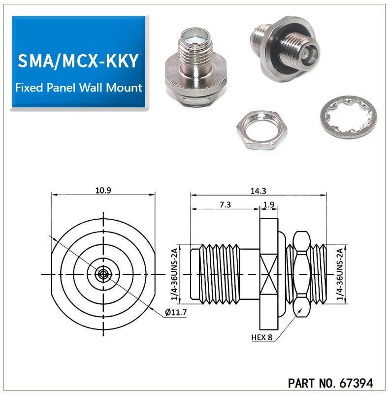
This is a technical drawing for a specific SMA panel mount connector (Part No. 67394). It provides critical dimensions such as the thread specification (1/4-36UNS-2A), the wrench flat size (HEX 8), overall lengths, and the recommended panel cutout diameter (Ø11.7mm). This image serves as a primary example for the document's discussion on ensuring mechanical compatibility between the connector and the enclosure panel.
Getting SMA connector dimensions right from the start saves more than production time—it prevents the kind of rework that frustrates engineers and delays shipments. A connector that’s a millimeter too short in thread length, a panel cutout that’s undersized, or a nut that doesn’t match the wrench can all stall assembly. I’ve seen teams waste hours redrilling panels or swapping parts just because these details were overlooked.
For both engineers and purchasing staff, the small numbers matter: 1/4–36 threads, 8 mm wrench flats, and even a 12.2 mm flange spacing. On paper they may look trivial, but in practice they decide whether the connector locks in smoothly or fights every turn.
At TEJTE, our SMA lineup includes bulkhead, flange, and PCB mount connectors. Each follows industry standards, but we also highlight practical details like washer stacks, O-ring compression, and torque values—things that often determine whether an install succeeds or fails. This guide walks through each critical parameter—threads, cutouts, flats, and seals—so you can check fit before ordering. Where needed, we’ll link to resources such as the RF connector families overview or deep-dive articles on plug, jack, and bulkhead styles.
Quick tip: Always double-check both the panel drawing and the datasheet. It takes five minutes and can save you from an afternoon of rework.
Confirm which SMA dimensions do you actually need for your design
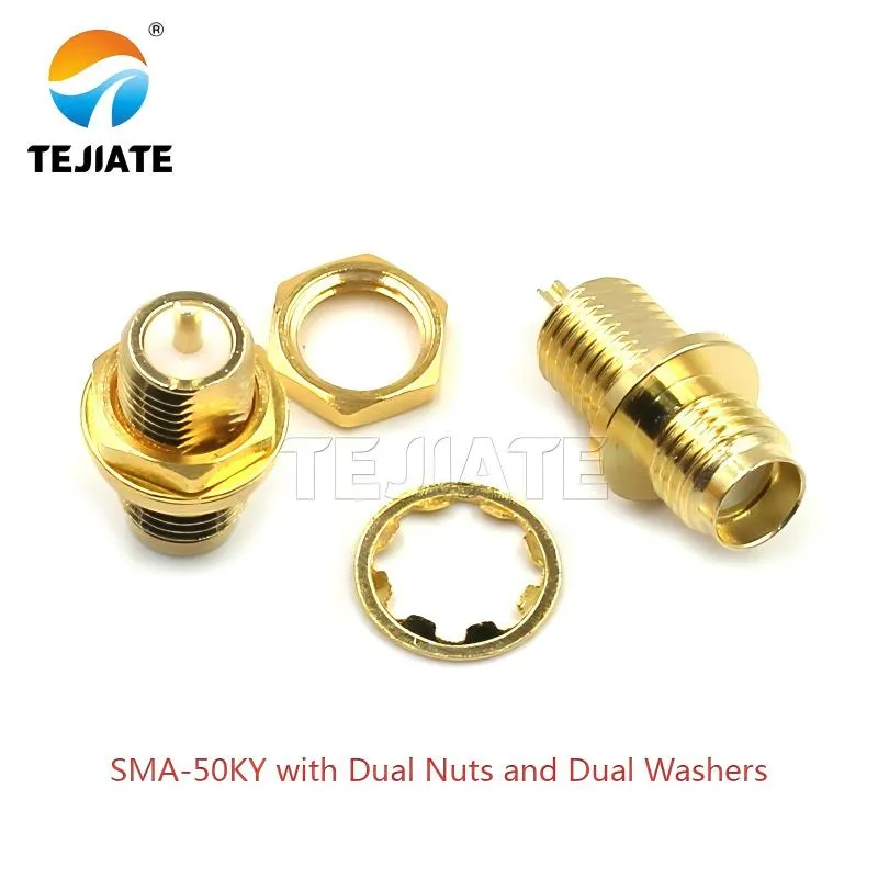
This image illustrates an SMA bulkhead connector (model SMA-50KY) configured with a dual-nut and dual-washer arrangement. This setup is typical for achieving a secure, vibration-resistant, and potentially weatherproof mount. The document uses this example to emphasize the importance of accounting for the total stack-up thickness (including washers and seals) when calculating the required thread length to ensure proper nut engagement.
Every design starts with a basic check: which SMA connector dimensions really matter for your application? The thread interface itself is standardized—1/4–36 UNS-2A, giving a 6.35 mm major diameter—but the details beyond that can vary widely, and that’s where mistakes usually creep in.
- Thread length: Options include 6.3 mm, 7.3 mm, 8.5 mm, and even 11 mm. For instance, TEJTE’s SMA-50KY specifies about 7.3 mm usable thread length, making it a reliable choice for 1.5–2.0 mm aluminum panels with paint. If you’re working with thicker panels, lean toward the 8.5 mm or longer versions.
- Panel cutout: A hole of Ø6.5–6.6 mm generally balances clearance with engagement. Undersized holes—say Ø6.3 mm—often scrape plating or threads during install.
- Wrench flats: Most bulkhead connectors rely on Hex 8 (≈8 mm across flats). Using the wrong tool here leads to either stripped nuts or scratched panel surfaces.
- Flange hole spacing: Expect 12.2 mm center-to-center for two-hole flanges and closer to 16.5 mm for four-hole designs. Mix them up, and your panel may need to be redrilled.
- Keep-out envelopes: SMA jack housings can stretch from 10.9 mm to 14.3 mm, while plugs protrude differently depending on nut and washer stacks. Crowding them near USB or RJ45 ports often causes fit issues.
- O-ring and washer stack: Waterproof builds add 1.7–1.9 mm in stack height, directly cutting into usable thread. Forget to account for it, and the nut may barely catch.
These aren’t throwaway details. They determine whether your connector locks in securely or shakes loose under vibration. For more on jack-specific sizing, you can review the SMA Female Connector: Panel, Flange & PCB Mount guide.
Avoid mixing optical “SMA 905/906” with RF SMA
Calculate your panel cutout and thread engagement before checkout
Before ordering, it’s worth doing a quick check on two details: the panel cutout size and how much thread engagement you’ll have left once everything is stacked. Too short a thread, and the nut barely bites; too long, and the connector feels loose or shifts under torque. I’ve seen both happen, and in most cases, a five-minute calculation would have prevented the issue.
Here’s a simple dimension checker for sma connector dimensions, using TEJTE’s SMA-50KY bulkhead as an example:
| Parameter | Value / Rule | Example (TEJTE SMA-50KY) |
|---|---|---|
| Panel_Thickness (mm) | Your panel thickness | 1.5 mm aluminum |
| Finish_Thickness (mm) | Coating or paint | 0.1 mm |
| Washer_Total (mm) | Stack of flat/lock/insulator washers | 0.5 mm |
| Nut_Engagement (mm) | Minimum thread bite | ≥2.0 mm |
| O-ring_Compression (mm) | 10–25 % of thickness | 0.8 mm |
| Product Thread Length (mm) | Connector spec | 7.3 mm |
| Thread Major Diameter (mm) | 1/4-36 UNS = 6.35 mm | 6.35 mm |
| Clearance (mm) | Recommended allowance | 0.2 mm |
| Flange_Hole_Spacing (mm) | Vendor datasheet | 12.2 mm |
Formulas to apply:
- Required_Thread_Length = Panel_Thickness + Finish_Thickness + Washer_Total + Nut_Engagement + O_ring_Compression
- Panel_Cutout_Diameter = Thread_Major_Diameter + Clearance
If Required_Thread_Length ≤ Product_Thread_Length → Pass.
If not, pick a longer thread version or trim down the washer stack.
For a standard 1/4–36 thread size, the calculation works out to 6.35 mm + 0.2 mm = 6.55 mm recommended hole. That extra clearance helps prevent galling without leaving the connector wobbly.
Quick tip: If you’re building a waterproof assembly, don’t forget O-ring compression. A compressed O-ring can “steal” 0.3 mm or more of usable thread. It’s one of the most common reasons why bulkhead SMA nuts feel like they’re only catching a turn or two. For examples of waterproof stack-ups, check the SMA Bulkhead Connector: Panel Mount, Flange Types & Waterproof Use.
Do your wrench flats and torque tools match the connector?

This diagram helps identify the correct wrench size (8 mm) and torque requirements to prevent nut damage or panel scratches.
The sma nut size is one of those details that often gets overlooked until you’re holding the wrong tool. Most SMA connectors use a HEX 8 nut, which translates to about 7.9 mm across flats (≈5/16 inch). On paper, it seems minor. In practice, using the wrong wrench can either round off the nut or leave scratches across the panel surface—both problems that are tough to fix once assembly is underway.
Torque matters just as much as the fit. Standard SMA connectors are designed to be tightened to 0.45–0.56 N·m. If you go lighter, vibration will eventually loosen the connection. Push harder, and you risk damaging the thread interface or even cracking the dielectric. Production teams often stick with torque wrenches to avoid these extremes—it’s about consistency as much as safety.
Here’s a quick field reminder: don’t reach for pliers or oversized spanners when you’re missing the right tool. It might “work” for one install, but by the second or third cycle the plating will show scars, and RF leakage isn’t far behind. The best practice is keeping a small 8 mm torque wrench in your kit. If you’d like to see how plugs compare on torque handling and mounting, check the SMA Male Connector: Plug, Panel & PCB article.
Convert inch specs to mm (1/4–36 thread, 5/16" flats) without mistakes
One of the easiest ways to derail a build is through sloppy unit conversion. Many American datasheets list sma connector dimensions in inches, while most CAD drawings and machining setups outside the U.S. expect millimeters. It sounds simple, but I’ve seen engineers round 5/16″ to 8.0 mm instead of the correct 7.94 mm. That tiny difference is enough to create loose wrench fits or cut threads during assembly.
Here are the numbers you need to keep straight:
- sma thread size: The standard 1/4–36 UNS-2A equals a 0.250″ major diameter (≈6.35 mm). The “36” means 36 threads per inch, which gives a 0.706 mm pitch.
- Wrench flats: 5/16″ = 7.94 mm. It’s tempting to round it off, but that shortcut usually backfires when tolerances are tight.
- Panel cutout: A safe calculation is Ø6.55 mm (6.35 mm thread + 0.20 mm clearance). That little buffer keeps the part from binding without letting it wobble.
A quick tip from the shop floor: always lock conversion factors into the actual drawing, not just a side note. One vendor may work to four decimals, while another rounds at two. Over a dozen connectors, those errors accumulate. For a broader comparison across connector families, check TEJTE’s RF Connector Guide.
What does “1/4–36” actually mean?
Here’s the breakdown:
- 1/4 → the nominal major diameter, 0.250″ (~6.35 mm).
- 36 → threads per inch (TPI).
- UNS-2A → Unified National Special, external thread, class-2A fit.
One mistake I see often is treating 1/4–36 as if it were metric M6×0.5. They look similar, but the pitch is different. An SMA nut on an M6 thread either binds or slips, and both cases ruin the connector. The lesson: don’t assume “close enough” is acceptable—thread standards are precise for a reason.
Should you choose bulkhead, flange or panel-mount for your enclosure?
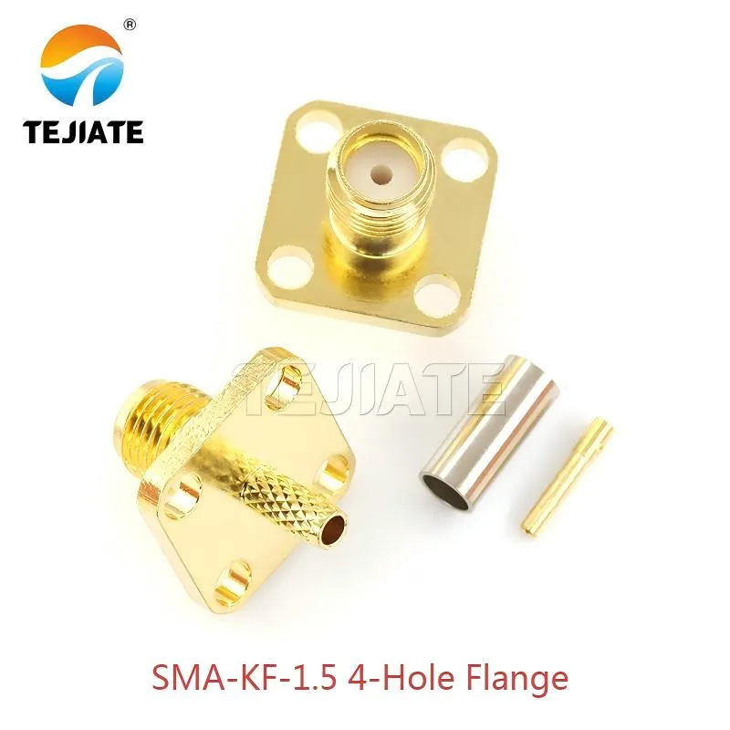
This technical drawing provides the precise dimensions for a 4-hole flange mount SMA connector (model SMA-KF-1.5). It clearly indicates the flange hole spacing (e.g., 16.5 mm pattern mentioned in text), which is critical for drilling accurate mounting holes in the panel. The document discusses flange mounts as a superior option for distributing stress and preventing rotation, especially in vibrating environments or on thin sheet metal.
Picking between bulkhead, flange, and panel-mount SMA connectors isn’t just a mechanical choice—it shapes how reliable and serviceable your final product will be. Each style has its place, and the differences often come down to wall thickness, torque distribution, and ease of access during assembly.
- Bulkhead SMA: The go-to option for many engineers. When reviewing sma bulkhead connector dimensions, you’ll notice common thread lengths of 6.3 mm, 7.3 mm, and 8.5 mm. TEJTE’s SMA-50KY, for example, provides a 7.3 mm thread length—perfect for painted 1.5–2.0 mm aluminum panels. For walls thicker than 3 mm, choose the longer 8.5 mm version so the nut can still grab securely.
- Flange-mount SMA: Better for thin sheet metal or when vibration is a concern. TEJTE’s SMA-KF-1.5 uses 12.2 mm hole spacing in its 2-hole version, while the 4-hole stretches to 16.5 mm. By spreading the load, the flange prevents torque stress from distorting the panel.
- Panel-mount SMA: A hybrid design that uses a rear nut and a flange face. This makes it easier to install or replace connectors in modular enclosures, especially when serviceability matters.
A quick reality check: think beyond catalog drawings. Ask yourself—can a technician actually tighten the nut inside a crowded rack? Will replacing a connector in the field mean dismantling the entire enclosure? For waterproof cabinets, always remember to factor in the O-ring and washer stack (see SMA Bulkhead Connector: Panel Mount, Flange Types & Waterproof Use). These little considerations decide whether your design is smooth to assemble—or a constant source of complaints.
Check plug vs jack envelopes and keep-out zones around the port
Not every SMA connector has the same body profile. The sma plug dimensions and sma jack dimensions differ enough that ignoring them often leads to assembly headaches.
- Plug: Typically shorter in body but sticks out beyond the panel. Standard lengths range from 10.9 mm to 14.3 mm, and most use knurled coupling nuts. That extra projection means you need finger clearance for tightening.
- Jack (female SMA connector dimensions): Usually recessed slightly, with the dielectric visible at the front. TEJTE’s SMA-KF-1.5 measures about 16.5 mm overall length, flange and barrel included.
- Envelope clash: Adjacent ports must be spaced at least 12 mm center-to-center so the coupling nuts can rotate without scraping each other.
- Washer stacks: Adding an insulating washer or lock washer increases stand-off height by 0.5–1 mm, which shifts the envelope outward. That tiny change can block a nearby USB, RJ45, or even another RF connector.
Practical tip: Always define keep-out zones in 3D CAD, not just 2D drawings. It’s one of those details you’ll regret skipping. Many engineers discover late in the process that SMA connectors collide with neighboring ports. If you plan to use female-to-female couplers, the SMA Female to Female Adapter Guide explains how spacing impacts usability—and when a short pigtail is the smarter move.
Will waterproof O-rings and washers change your stack-up?
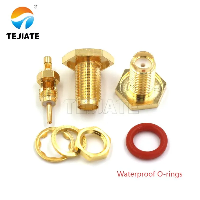
This image showcases a silicone O-ring, a key component for achieving waterproof (e.g., IP67) seals with SMA bulkhead connectors. The document specifically discusses how compressing an O-ring (typically by 10-25% of its thickness) consumes a portion of the available thread length (around 0.3 mm), which must be factored into the design calculations to avoid insufficient nut engagement.

This is a close-up image of a washer, a critical but often overlooked component in the installation stack-up. The document repeatedly stresses that the combined thickness of washers, seals, and panel coatings must be subtracted from the connector's available thread length to ensure the nut can engage sufficiently. This picture highlights one of these essential components.
The answer is simple: yes. Seals and washers have a direct impact on sma connector dimensions that actually work in your build. A bulkhead connector without a washer stack behaves very differently from a waterproof version that includes silicone O-rings and extra hardware.
Take TEJTE’s SMA-KF-1.5 as an example. The O-ring measures about 1.7 mm thick, and once compressed, it loses around 15–20% of its height. That means you’re giving up roughly 0.3 mm of usable thread engagement right away. Add in a flat washer or lock washer, and you can quickly eat another half millimeter. If you don’t allow for that in your calculations, the nut may only catch two turns—and that’s asking for trouble in the field.
Here’s a simple check engineers like to use: add panel thickness, finish, washer stack, and O-ring compression together. If that number comes too close to the connector’s thread length, you’re on thin ice. For a 2 mm aluminum panel plus 0.5 mm of washers and 0.3 mm O-ring compression, you’ve already consumed 2.8 mm before the nut even bites. On a short 6.3 mm bulkhead thread, the margin is slim.
Field tip: When sealing outdoor enclosures, always pick the longer 8.5 mm thread version. It gives you breathing room and avoids failures caused by over-compression. For more detail on gasket stacks and sealing practices, check our SMA Bulkhead Connector: Panel Mount, Flange Types & Waterproof Use.
Plan PCB edge/RA clearances for edge-mount and right-angle jacks
Board-mounted SMA connectors bring their own set of design rules, and ignoring them often leads to rework. The sma edge connector dimensions and right-angle footprints need extra clearance to avoid copper conflicts, blocked solder joints, or unstable impedance.
- Edge-mount SMA: The dielectric shoulder is typically 3.8 mm long, and you’ll need room for proper solder fillets. Expect the housing to hang 1–2 mm past the PCB edge, which can interfere with other boards or mounting brackets if not planned.
- Right-angle SMA: These add vertical rise. TEJTE’s catalog lists versions around 16.5 mm in total height, with the center pin soldered through plated vias. If tall components like RJ45 or USB-A ports sit nearby, spacing becomes critical.
- Keep-out rules: Leave at least 1 mm of solder mask opening around the launch pad, and surround it with a ground via fence spaced roughly 1.0 mm apart. This helps control impedance and keeps RF leakage low.
- Rework considerations: Think about the technician doing repairs. If the nut is too close to other tall components, there won’t be room for an iron tip or hot-air nozzle.
Practical advice: always run a 3D clearance check in CAD. A connector that looks fine on a flat drawing might block airflow, cables, or even heat sinks once assembled. For more examples of how PCB-mount SMA plugs are handled, take a look at our SMA Male Connector: Plug, Panel & PCB guide.
Avoid RP-SMA dimension pitfalls before ordering
At a glance, RP-SMA and SMA look almost identical, which is why mix-ups are so common. The threads are the same—1/4–36 UNS with a Ø6.5 mm panel cutout—but the internal contact layout is reversed. That single difference changes everything about how the connectors mate.
Here’s the breakdown:
- SMA plug → male pin inside.
- RP-SMA plug → female socket inside.
- SMA jack → female socket inside.
- RP-SMA jack → male pin inside.
From the outside, they share the same Hex 8 nuts (≈7.9 mm across flats) and similar housings. This is why many drawings look correct even when the wrong connector has been specified. The issue only shows up when parts arrive and nothing fits. Checking the rp-sma connector dimensions carefully against the BOM is the simplest way to avoid this headache.
Field reminder: always add a clear note in the documentation—“RF SMA, not RP-SMA”—especially if the order is going overseas or handled by multiple vendors. For high-volume production, it’s often safer to source through suppliers who label the difference clearly, such as TEJTE’s RF Adapter & Cable assemblies.
If you’re still unsure, do a visual check before committing parts to the line. Spotting the wrong pin type at the bench is a five-second task that can save days of rework. For more context on jack geometry and couplers, see our SMA Female to Female Adapter Guide.
Verify that N/BNC/TNC dimensions are not interchangeable with SMA
It’s a mistake I’ve seen more than once: engineers assuming that if connectors look similar, they’ll fit the same panel hole. In reality, sma connector dimensions are unique, and mixing them with other RF families leads to damaged hardware or failed assemblies.
Here’s how the sizes compare:
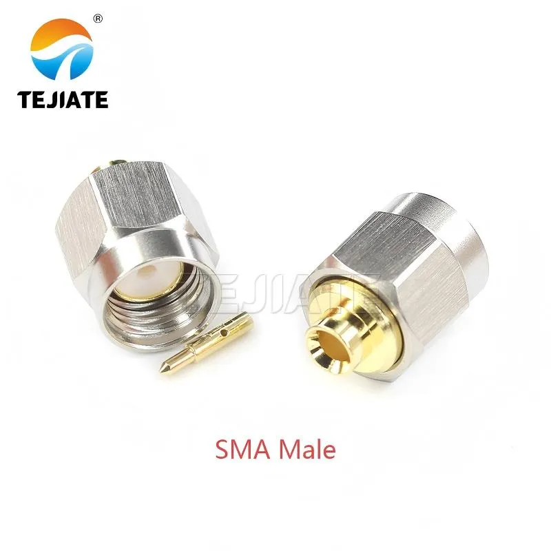
This is a product photo of a standard SMA male connector. It serves as a visual reference for the connector type being discussed throughout the document. The image helps contextualize the technical dimensions (like the 1/4-36 thread) by showing the physical connector they apply to. It is used in the section comparing SMA dimensions to other connector families like N-type.
- SMA → 1/4–36 thread, ~6.35 mm major diameter, fits a Ø6.5 mm cutout.
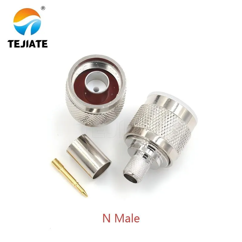
This image presents an N-type male connector. Its primary purpose in the document is for size comparison. The text explicitly states that N-type connectors have a much larger thread diameter (~11 mm) and are mechanically incompatible with SMA cutouts. This visual reinforces the warning against attempting to use SMA panel holes for larger connector types.
- N-type → much larger, about 11 mm thread diameter. Far too big for an SMA hole.
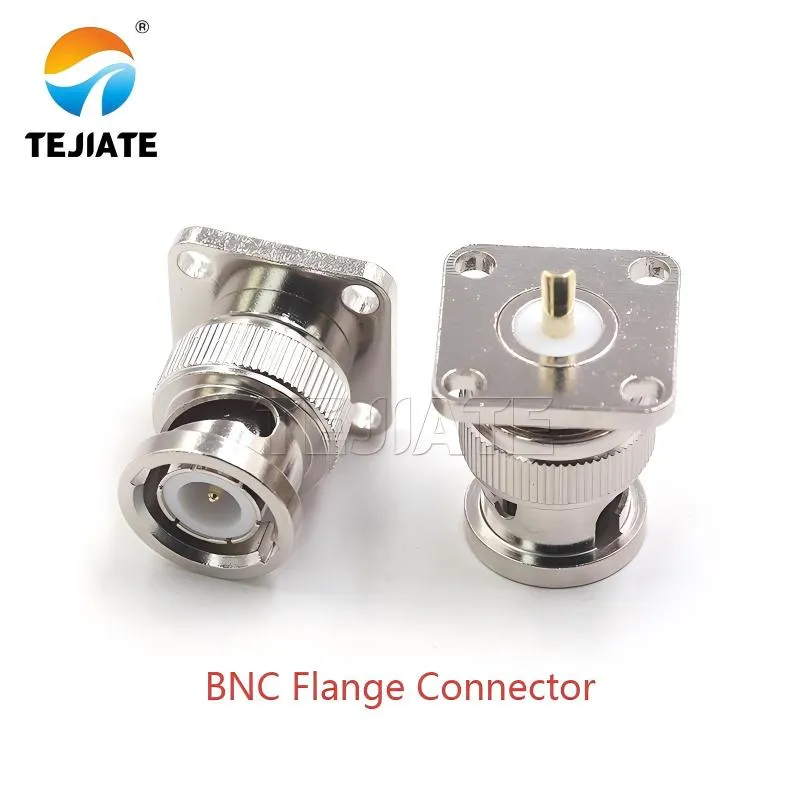
This figure depicts a BNC flange connector. The document uses it to illustrate another common RF connector type that is not mechanically interchangeable with SMA. It highlights that BNC connectors use a bayonet locking mechanism and have a body diameter around 14 mm, requiring a keyed slot rather than a simple threaded hole. This emphasizes the importance of using the correct panel cutout for each specific connector family.
- BNC → bayonet design, body diameter near 14 mm, requiring a keyed slot rather than threads.
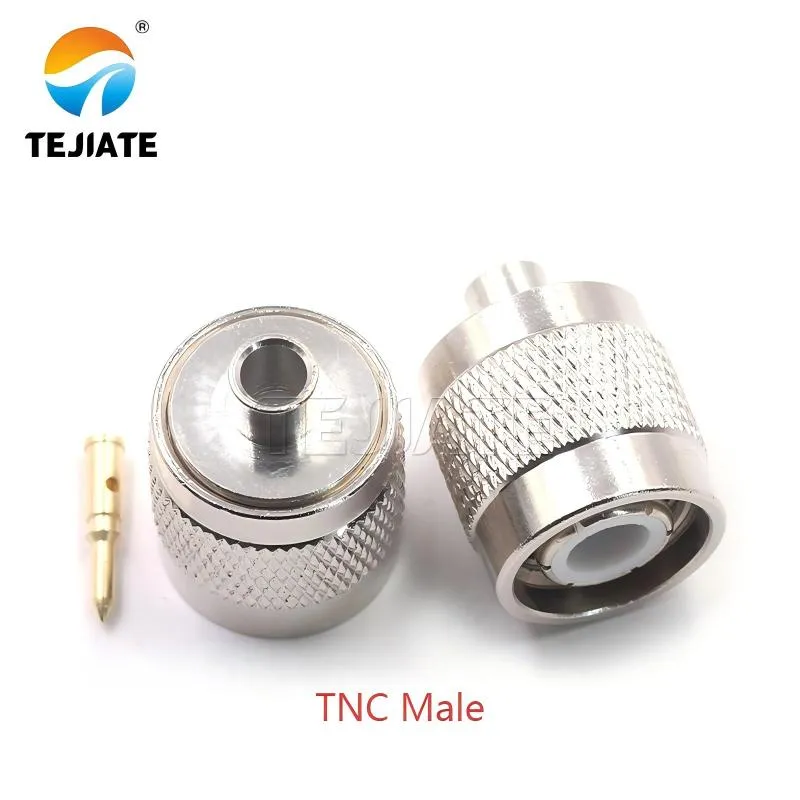
This image shows a TNC male connector. The document includes it as the final example in its comparison of different RF connector families. It notes that while TNC is a threaded version of BNC, it still has a larger major diameter (~9.7 mm) compared to SMA and is not compatible. The image helps visually cement the concept that each connector type has unique dimensional requirements.
- TNC → threaded cousin of BNC, around 9.7 mm major diameter, still incompatible with SMA.
The problem isn’t just diameter. Torque ratings, dielectric clearances, and sealing surfaces all differ. Oversizing a panel hole to “make it work” leaves you with threads that won’t bite and seals that won’t hold.
Practical takeaway: when cross-family connections are required, don’t modify panels—use adapters. TEJTE offers a range of RF adapters and cables that safely bridge SMA to N, BNC, or TNC while preserving both fit and RF performance. For a full comparison of connector families, check our RF Connector Guide.
The bottom line: “close enough” is never close enough with RF connectors. Each series was designed for a specific geometry, and treating them as interchangeable is asking for rework.
SMA Panel & Flange Dimension Checker
Before sending out a purchase order, it’s smart to double-check whether the sma connector dimensions you’ve chosen actually work with your panel thickness, coatings, and washers. Skipping this step often leads to connectors that don’t seat properly, flange holes that don’t align, or nuts that barely catch.
Here’s a structured checker you can adapt for your design:
| Field | Input (mm) | Example: TEJTE SMA-KF-1.5 | Pass/Fail Rule |
|---|---|---|---|
| Panel_Thickness | 2.0 | 2.0 mm aluminum | — |
| Finish_Thickness | 0.1 | Powder coat | — |
| Washer_Total | 0.5 | Lock + flat | — |
| Nut_Engagement | ≥2.0 | 2.0 mm | Minimum thread bite |
| O-ring_Compression | 0.3 | From 1.7 mm seal | 10–25 % |
| Product_Thread_Length | 7.3 | TEJTE SMA-50KY | Must ≥ Required |
| Thread_Major_Diameter | 6.35 | 1/4-36 UNS | +0.1–0.3 mm clearance |
| Clearance | 0.2 | Machining tolerance | — |
| Flange_Hole_Spacing | 12.2 | TEJTE SMA-KF-1.5 | Must match ±0.1 mm |
Formulas to use:
- Required_Thread_Length = Panel_Thickness + Finish_Thickness + Washer_Total + Nut_Engagement + O_ring_Compression
- Panel_Cutout_Diameter = Thread_Major_Diameter + Clearance
If Required_Thread_Length ≤ Product_Thread_Length → Pass.
If not, upgrade to a longer-thread connector or reduce the washer/O-ring stack.
Example: with a 2.0 mm panel, 0.1 mm paint, 0.5 mm washer, and 0.3 mm O-ring compression, the required total is 2.9 mm. On a 7.3 mm bulkhead thread, you’re safe. But if you’d picked the shorter 6.3 mm style, you’d likely fail.
Pro tip: always confirm flange hole spacing against the datasheet. TEJTE’s 2-hole SMA-KF-1.5 specifies 12.2 mm, while the 4-hole flange stretches to 16.5 mm. Confusing them during fabrication often leads to redrilling, wasted panels, and lost time.
FAQs
What panel hole size should I use for an SMA bulkhead with 1/4–36 threads?
Most designs work best with a Ø6.5–6.6 mm cutout. If the panel has paint or anodizing, choose the larger end to prevent scraping the finish. Undersizing the hole often damages threads during installation.
Are SMA and RP-SMA hex nuts the same wrench size?
Yes. Both use a standard Hex 8 nut (~7.9 mm across flats). The difference lies in the center contact, not the nut. A quick reminder: always check the pin/socket arrangement, not just the hex.
How much thread engagement is safe for a 2 mm painted aluminum panel?
Aim for at least 2.0 mm of thread bite. With TEJTE’s 7.3 mm bulkhead thread, you’ll still have about 2.5 mm engagement left after accounting for paint, washers, and O-ring compression. That margin is what keeps connections reliable under vibration.
Do 2-hole SMA flanges follow a standard hole spacing, or does it vary by vendor?
Most use 12.2 mm center spacing, but tolerances can vary slightly. Always confirm with the datasheet before drilling. TEJTE’s SMA-KF-1.5 is a good reference point for production panels.
Will adding an O-ring and insulating washer change the required thread length?
Definitely. O-rings and washers can add 0.5–1.0 mm to the stack. If you’re using a short-thread connector, consider stepping up to the 8.5 mm version to avoid under-engagement.
Is 1/4–36 UNEF equivalent to metric M6×0.5 for SMA panel cutouts?
No. Although they look close, the pitch is different. Mixing them causes cross-threading or loose fits. Stick with the specified sma thread size for accuracy.
Can “SMA 905” optical connectors share dimensions with RF SMA parts?
No. SMA 905/906 are optical standards designed for fiber ferrules. They are not mechanically or electrically compatible with RF SMA connectors.
Bonfon Office Building, Longgang District, Shenzhen City, Guangdong Province, China

A China-based OEM/ODM RF communications supplier
Table of Contents
Owning your OEM/ODM/Private Label for Electronic Devices andComponents is now easier than ever.
