
A connector can fit the panel, mate smoothly, and still be the wrong interface for the installed RF system.
This usually happens because the N Type connector is selected as an isolated part. The engineer confirms male or female, checks that the thread engages, and then moves on to the cable. But a field RF connection is not only a connector interface. It is a mechanical and electrical boundary between equipment, coaxial cable, antenna infrastructure, environmental exposure, and sometimes a smaller internal RF interface such as SMA.
That distinction matters once the installation leaves the bench.
A short jumper sitting straight on a test table places very little load on the connector. The same assembly installed inside an enclosure may be bent immediately behind the rear body, connected to a heavy feeder, or pulled sideways by outdoor cable routing. A mechanically convenient substitution can also introduce the wrong impedance or an unqualified transition.
Which System Boundary Should Define the N Type Interface?
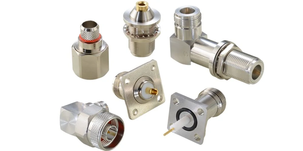
A selection of straight, right-angle, bulkhead, flange-mount, and cable-mount N Type connectors for field RF system integration.
Start With the Fixed Outdoor or Equipment Port
Start from the part of the system that is least flexible.
In an antenna installation, that may be the antenna feed point. In a radio enclosure, it may be the chassis opening. In test equipment, it may be the front-panel RF port. For field wiring, the fixed point may instead be a lightning protector, feeder entry, or bulkhead transition.
The location changes what the n connector has to do.
An N Type connector used directly on a flexible jumper has different mechanical requirements from an N bulkhead carrying a large outdoor feeder through a metal enclosure. The RF interface may look similar from the front, but the mounting method, rear geometry, cable support, environmental sealing, and service load can be completely different.
This is why connector selection should begin with the installed boundary rather than a catalog photograph.
Each arrow represents a point where electrical or mechanical behavior can change.
The internal connection may prioritize compact size and short routing. The chassis transition has to transfer mechanical load into the enclosure. The external feeder may prioritize lower attenuation, larger cable diameter, outdoor durability, and stronger strain control. The n type antenna connector sits at the boundary between those requirements.
Separate Internal RF Connections From Field-Facing Interfaces
Compact RF modules often use SMA because the interface is relatively small and works well with short internal coaxial assemblies. That does not mean the same interface should carry the external feeder.
A thick or stiff coaxial cable can generate bending moment at the port. If that load is transferred directly to a PCB-mounted SMA connector, the weak point may no longer be RF performance. It may become solder-joint fatigue, panel movement, connector rotation, or damage caused during installation.
A chassis-mounted N interface creates a cleaner mechanical boundary. The heavier external cable can be supported at the enclosure, while a short flexible coax section connects the bulkhead to the internal RF module.
This arrangement also helps production. The external cable configuration can change without forcing a redesign of the PCB interface, provided the approved RF transition remains controlled.
The key procurement point is simple: the connector description should identify where the interface is used, not just its gender.
“50 Ω N female bulkhead for enclosure feed-through” gives the supplier far more useful information than “N female connector.”
Define the Complete Signal Path Before Selecting the Connector
Before freezing a part number, trace the RF path from the radio to the antenna.
Check which interface is fixed, where the cable changes size, where adapters are introduced, where mechanical load enters the assembly, and which connection will be serviced in the field.
This avoids a common sourcing problem: approving the connector first and discovering later that the rear termination does not fit the selected cable, the feeder cannot meet the required bend radius, or an unnecessary SMA-to-N transition has been added simply to recover from the original interface choice.
The N Type connector should be selected as part of a controlled RF assembly, not as an independent hardware item.
How Do You Verify 50Ω or 75Ω Before Checking Mechanical Fit?
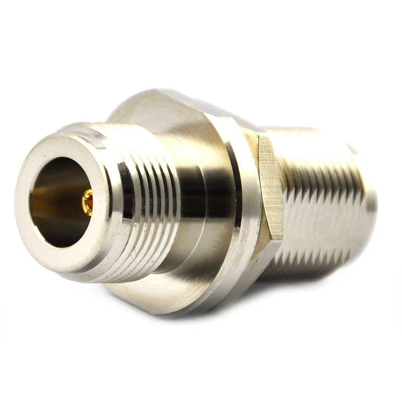
Panel-mount N Type female bulkhead connector used to create a controlled RF transition through an equipment enclosure.
Match Equipment, Connector, and Cable Impedance Together
If one item is different, stop the mechanical selection process and resolve the electrical architecture first.
A 50 Ω radio connected through a 50 Ω n type rf connector should normally continue into a 50 Ω coaxial path unless the system intentionally includes a designed impedance-transforming network. Substituting a different impedance because the connector shell looks similar is not an acceptable production shortcut.
The same applies to purchased cable assemblies. Continuity testing may show a good DC path while completely missing an RF mismatch.
At the operating band, the consequences may appear as poorer return loss, increased VSWR, unstable measurement results, or system behavior that differs between the bench sample and the installed unit.
That is the point where N Type integration becomes an engineering qualification task rather than a connector-matching exercise.
Which Cable and Rear-Termination Geometry Controls Fit?
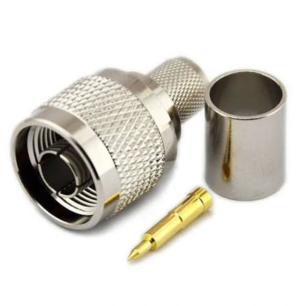
Disassembled N Type male crimp connector showing the connector body, crimp ferrule, and center contact used for coaxial cable termination.
The front interface is only half of an N Type connector.
Two connectors can mate with the same N port while having completely different rear bodies. One may be intended for RG58-size coax. Another may be designed for RG213, LMR-400, or a semi-rigid cable. If the buyer specifies only “N male connector,” the supplier still does not know what has to happen behind the coupling nut.
Select the N-Type Rear Body From the Actual Coax
Cable compatibility should be checked against the real cable part number, not only a cable family name.
For example, RG58, RG213, LMR-240, and LMR-400 differ substantially in outside diameter, dielectric size, center-conductor construction, shielding, and stiffness. A connector that accepts one cable cannot be assumed to accept another simply because both are 50 Ω.
These values determine whether the cable can actually be terminated with controlled contact pressure and repeatable geometry.
A loose ferrule can leave poor braid contact. An undersized rear entry can damage the jacket during assembly. A center pin designed for a larger conductor may not crimp or solder correctly to a smaller one. Those are assembly faults, but they often appear later as RF faults.
Choose Crimp, Clamp, or Solder From the Assembly Process
Termination style should follow the connector design and cable construction.
Crimp termination is attractive for repeatable production because tooling can be controlled. Clamp-style designs are common where the connector mechanically captures the cable structure. Solder may still be used for the center conductor or shield on specific designs, but soldering introduces another process variable: heat.
Too much heat can deform dielectric material, shift the center conductor, or create an inconsistent transition close to the RF interface.
How Should the N-Type Interface Carry Mechanical Load?
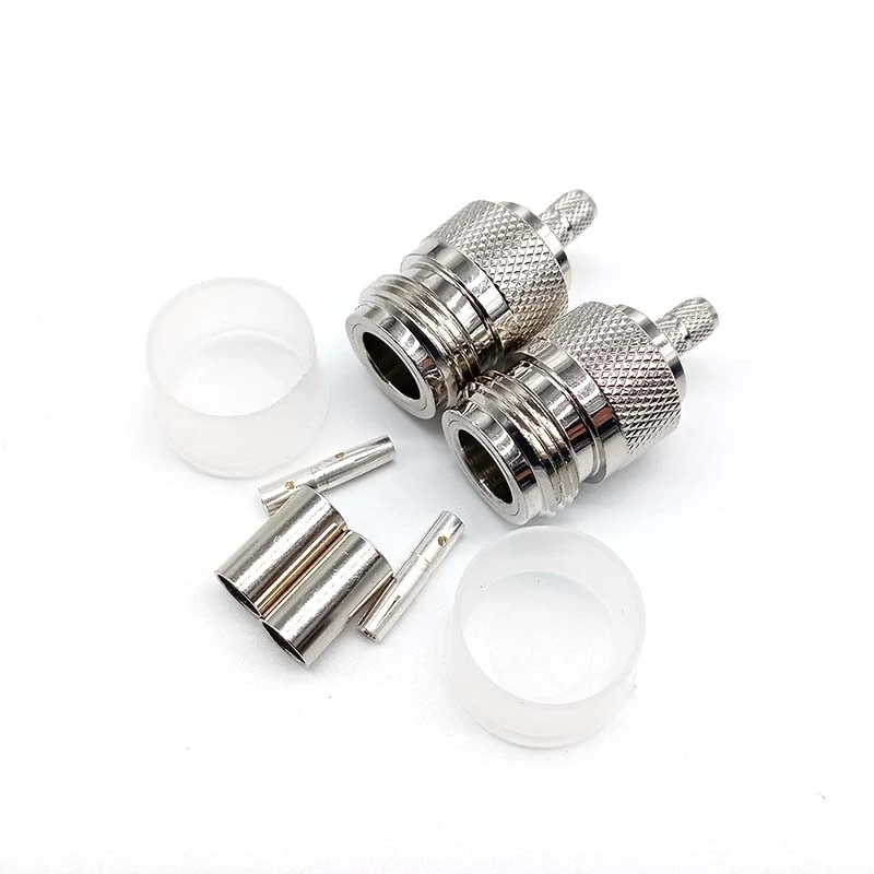
Two N Type cable connector assemblies with center contacts, ferrules, and insulating components for mechanically supported RF cable termination.
A heavy feeder should not use the RF contact as its strain-relief system.
Large coaxial cables can apply considerable pull force and bending moment, especially near outdoor equipment where the cable drops vertically, changes direction, or is tied to a support structure.
Keep Heavy Feeder Loads Off Small Internal RF Ports
This becomes particularly important when the external feeder is transitioned to a compact SMA connector inside the enclosure.
The SMA interface may be electrically suitable for the internal RF module, yet mechanically unsuitable for the full feeder load. If a stiff cable is routed directly to a PCB-mounted SMA port, the connector, solder joints, or PCB can become the load-bearing structure.
The enclosure now absorbs the external load.
The internal cable only has to accommodate routing, vibration, manufacturing tolerance, and service movement.
Add Strain Relief Before the Cable Bends
Connector damage often starts behind the connector, not at the mating thread.
If the first cable support point is too far from the rear body, the connector may repeatedly absorb bending force as the cable moves. This can loosen clamps, rotate the body, fatigue the braid termination, or change the cable geometry immediately behind the interface.
Cable support should therefore be evaluated in the final installed position.
A cable that looks acceptable on an open bench may be forced into a much tighter bend after the enclosure door closes.
That change matters because cable bend radius, connector orientation, and strain-relief position interact.
The installed geometry should be part of first-article approval, not left to the field technician.
When Should You Transition Between SMA and N-Type?
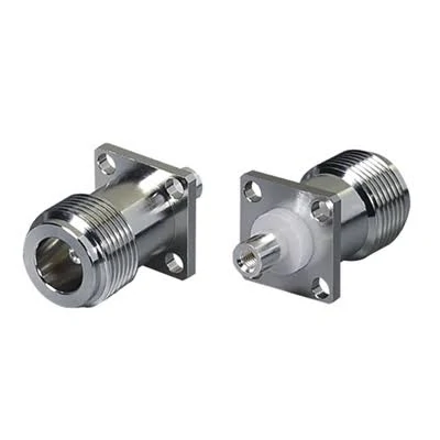
Front and rear views of an N Type female four-hole flange connector designed for equipment panels and controlled internal RF transitions.
SMA and N-Type often appear in the same system because they solve different packaging problems.
SMA works well around compact radios, PCBs, modules, and short internal cable assemblies. N-Type is more practical at many field-facing boundaries where the external cable is larger or where a stronger mechanical interface is needed.
The question is not whether the two connector families can be converted. They can.
The real question is how to make that transition without creating unnecessary RF and mechanical risk.
Use a Rigid Adapter Only When the Ports Are Mechanically Aligned
A rigid SMA-to-N adapter is reasonable when two ports are close, coaxially aligned, and mechanically stable.
The problem starts when the adapter is asked to compensate for offset.
A rigid adapter cannot absorb enclosure tolerance, vibration, or thermal movement. If two ports are slightly misaligned, tightening the adapter may force one connector sideways. The electrical path may work while the mechanical preload remains hidden.
That preload can later show up as loose mating, port damage, or unstable RF results after vibration.
Use a Flexible Cable Assembly When Offset or Vibration Exists
A short flexible SMA-to-N cable assembly is often safer when the two interfaces are separated or misaligned.
It can absorb:
- port offset
- enclosure tolerance
- vibration
- installation movement
- thermal expansion
The cable also reduces the mechanical leverage that a long rigid adapter stack can place on a small SMA port.
A permanent RF path should also avoid unnecessary adapter stacking.
may be convenient during prototyping, but every additional interface adds another potential mismatch, mechanical joint, inspection point, and maintenance location.
For production, count every transition in the RF budget.
The connector itself may have low loss, yet the complete assembly can still underperform after multiple adapters, a long coax run, tight routing, and imperfect termination are combined.
The production goal should therefore be simple: use the fewest justified transitions, support them mechanically, and verify the complete installed RF path rather than assuming each individual component will guarantee the final result
bration, service work, or repeated mating, inspect the interface again. Threads, center contacts, cable support, and sealing can change during use.
Which RF Tests Reveal Integration Problems?
Visual inspection can confirm assembly condition. It cannot prove RF behavior.
Use S11 to Evaluate Installed Reflection
For an installed N Type connector path, S11 measurement can reveal reflection problems caused by mismatch, poor termination, connector stress, or an unsuitable transition.
Useful acceptance metrics include:
- return loss
- VSWR
- impedance discontinuity
- stability across the operating band
The measurement should cover the actual application frequency rather than a convenient low-frequency point.
Use S21 When the Interface Is Part of a Cable Assembly
If the N connector is part of a complete cable path, S21 helps evaluate transmission loss through the assembly.
Testing the loose connector alone may miss cable attenuation, adapter loss, termination defects, or routing effects.
When that happens, check the installation before rejecting the connector itself.
Typical causes include cable routing, bend radius, mechanical stress, adapter transitions, poor mating, or changes introduced by the enclosure.
How Can You Qualify the Complete N-Type Boundary?
A practical release decision should combine electrical, mechanical, environmental, and sourcing checks instead of treating them as separate departments.
N Type Field Integration Matrix
| Verification Field | Engineering Input | Supplier / Drawing Data | Approval Rule |
| Interface | N male / female | Exact mating interface | Compatible |
| Impedance | 50 Ω / 75 Ω | Rated impedance | Must match |
| Cable | Exact cable PN | Approved cable range | Match |
| Rear termination | Crimp / clamp / solder | Connector design | Match |
| Frequency | Required band | Rated range | Fully covered |
| Mounting | Cable / bulkhead / panel | Mechanical drawing | Compatible |
| External load | Pull / bend / weight | Support design | Controlled |
| SMA/N transition | Adapter / cable / none | Approved configuration | Verified |
| Environment | Indoor / outdoor | Qualified condition | Suitable |
| S11 / VSWR | Project limit | Test result | Pass |
| S21 / loss | If required | Test result | Pass |
The value of the matrix is not complexity. It is visibility.
If one field is still unknown, the assembly is not fully defined.
How Should Buyers Freeze the N-Type Configuration for Production?
Once the first article passes, the approved configuration should become difficult to change accidentally.
If an SMA-to-N transition is used, record that transition as well.
Do not allow a supplier to replace a flexible cable transition with a rigid adapter, or substitute another cable that “fits the connector,” without engineering review.
Changes that should trigger requalification include connector PN changes, cable supplier changes, termination-process changes, panel redesign, added adapters, operating-band changes, or new environmental requirements.
Production control is where many apparently small substitutions become expensive.
The prototype may still work. The problem is repeatability across hundreds or thousands of assemblies.
FAQ
Can an N Type connector be electrically correct but mechanically unsuitable?
Yes. Impedance and frequency may be correct while cable stiffness, feeder weight, bend radius, or mounting geometry creates excessive stress.
Why can an N Type assembly pass on the bench but fail after installation?
The installed cable may be bent tighter, loaded by a heavier feeder, compressed by the enclosure, or connected through additional transitions.
Can 50 Ω and 75 Ω N connectors be treated as interchangeable?
No. Confirm impedance before mating. Mechanical similarity does not make the interfaces electrically or mechanically equivalent.
Should a large feeder connect directly to an SMA device port?
Not automatically. A chassis-mounted N interface with a short flexible internal cable can keep feeder load away from the smaller RF port.
When is an SMA-to-N cable better than a rigid adapter?
Use a flexible cable when ports are offset, separated, exposed to vibration, or affected by enclosure tolerance.