
Aviation Connector Selection for Industrial Equipment
In many industrial machines, the connector is installed in a place that is rarely noticed until something goes wrong.
A loose connection can stop a control system. A damaged contact can interrupt sensor signals. A connector that is difficult to maintain can increase machine downtime during production.
This is why many equipment manufacturers choose an aviation connector for industrial applications.
Although the name contains “aviation”, these connectors are not limited to aircraft-related systems. The circular locking structure has made them common in factory equipment, automation systems, measurement devices, and electrical control applications.
For industrial designers, the key question is not whether a connector looks strong. The real question is:
Can the connector maintain a stable connection under the actual working conditions of the equipment?
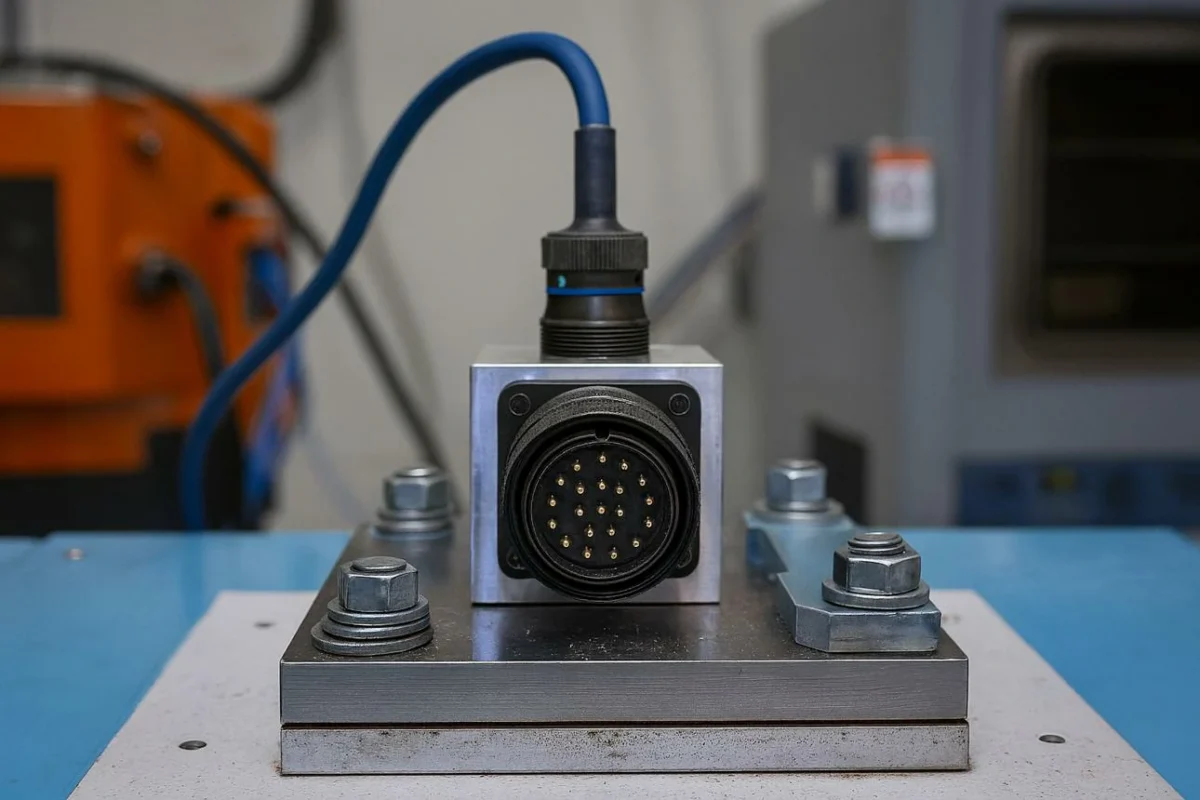
That depends on several factors:
- Connection frequency
- Mechanical vibration
- Required current and voltage
- Installation space
- Cable size
- Environmental conditions
A connector used inside a control cabinet may have completely different requirements from one installed on a moving machine.
How Should You Select an Aviation Connector for Industrial Equipment?
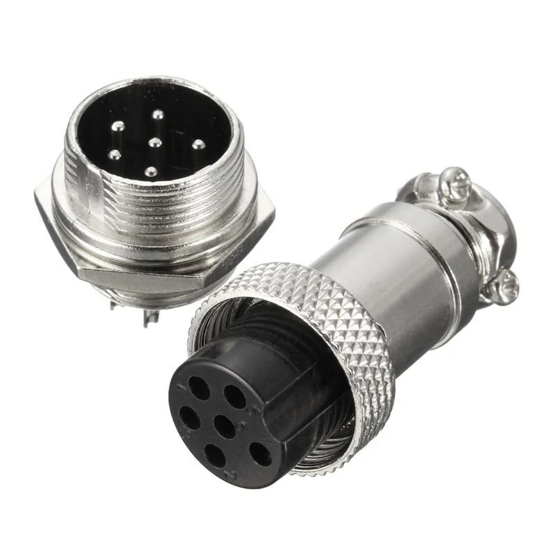
A GX16 5-pin aviation connector set consisting of a cable-side plug and panel-mount socket. The compact threaded connection is suitable for industrial control boxes, automation equipment, instruments, sensors, power circuits, and removable electrical interfaces.
Choosing an aviation connector usually starts with the equipment design rather than the connector itself.
Before requesting a quotation, engineers normally need to confirm where the connector will be installed and what signals it needs to carry.
For example:
A small sensor device may only require several signal contacts.
A motor control system may require:
- Power input
- Signal feedback
- Ground connection
- Control lines
Using the same connector solution for both situations may create unnecessary cost or reliability issues.
How Do Aviation Connectors Differ From Standard Industrial Connectors?
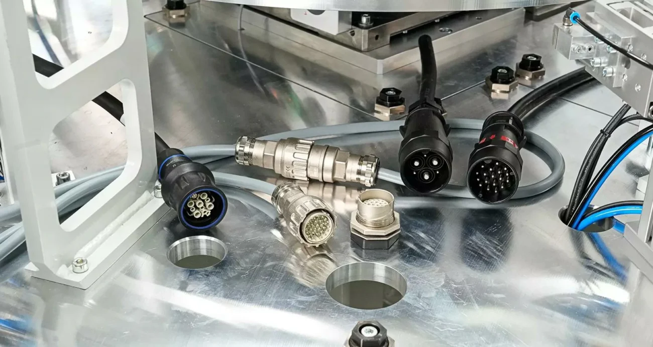
Industrial wiring can be completed in several ways.
The common methods include:
- Fixed cable connection
- Terminal block connection
- Circular connector connection
Each method has its own application area.
The difference is mainly related to maintenance and flexibility.
Compare Connection Methods Before Equipment Design
Industrial Connector Selection Comparison Table
| Item | Aviation Connector | Terminal Block | Fixed Wiring |
| Connection Method | Plug and socket | Screw terminal | Direct wiring |
| Maintenance Speed | Fast replacement | Medium | Slow |
| Vibration Resistance | Good with locking structure | Depends on installation | Depends on wiring |
| System Modification | Easy | Medium | Difficult |
| Suitable Application | Modular equipment | Control cabinet | Permanent installation |
In production environments, equipment changes are common.
A machine may require:
- Controller replacement
- Sensor upgrade
- Cable length adjustment
- Module maintenance
With fixed wiring, technicians usually need to disconnect and identify multiple wires manually.
With an aviation connector system, replacement is simpler because the interface remains standardized.
This is one reason circular connectors are widely adopted in industrial automation.
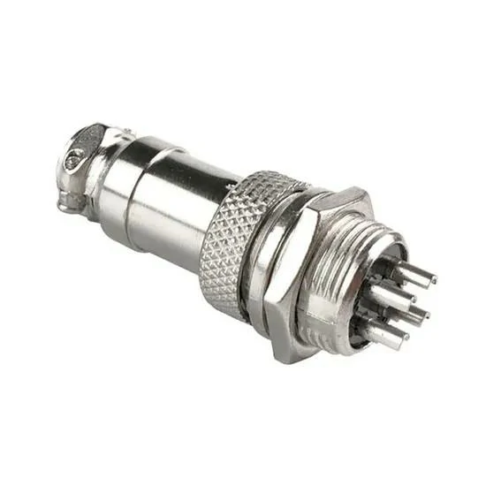
A close-up view of a metal GX series panel-mount aviation connector featuring multiple solder pins, a threaded housing, mounting nut, and cable retention structure. This connector style is commonly used in control boxes, instruments, sensors, and compact industrial equipment.
A GX16 connector used on industrial machinery may require stronger mechanical retention and better cable protection.
The connector model may be the same, but the final specification depends on the actual working condition.
GX16 Connector Specification Reference
| Parameter | Typical Description |
| Series | GX16 |
| Mounting Size | 16mm |
| Connector Type | Circular connector |
| Locking Method | Threaded locking |
| Contact Method | Solder connection |
| Pin Options | Multiple configurations |
| Application | Industrial equipment and control systems |
GX16 Connector Specification Table
viation Connector Guide for Industrial Applications
GX16 Pinout, Wiring, and Industrial Application Considerations
A connector can pass electrical signals, but a good connector solution needs more than simple continuity.
In actual equipment assembly, many connection problems appear after the prototype stage:
- The connector mates correctly but the machine does not start.
- The cable assembly works during testing but becomes unstable after installation.
- The connector specification is correct, but the wiring sequence does not match the control board.
These situations are usually related to interface details rather than the connector housing itself.
For GX16 connector applications, the pin arrangement, wiring method, and plug/socket matching are three areas that should be confirmed before production.
How Do GX16 Pinout and Wiring Affect System Reliability?
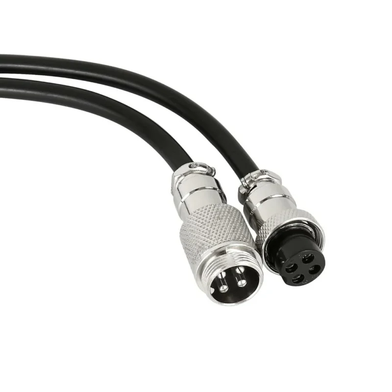
A GX16 connector is often selected because it provides a compact circular interface. However, the connector only provides the physical connection. The actual electrical performance depends on how the pins are assigned and how the cable is assembled.
In a custom cable project, the same GX16 connector may be used for completely different purposes.
One customer may use it for:
- DC power input
Another project may use the same connector for:
- Sensor signals
- Control signals
- Communication lines
The connector model alone cannot define the final wiring method.
The wiring information needs to be confirmed together with the equipment circuit design.
Check GX16 Connector Pinout Before Cable Assembly
Pin definition is one of the most common points that causes assembly mistakes.
A GX16 connector drawing normally needs to indicate:
- Pin numbering direction
- Plug viewing angle
- Socket mounting direction
- Cable-side wiring sequence
A common problem happens when the drawing view and actual soldering view are different.
For example:
The engineer checks the connector from the mating side.
The technician solders the cable from the rear side.
The pin position becomes reversed if the viewing direction is not clearly defined.
For prototype quantities, this mistake may only waste assembly time.
For production quantities, it can affect an entire batch of cable assemblies.
Separate Power and Signal Connections Properly
In many compact industrial devices, one connector may carry multiple types of circuits.
A typical arrangement may include:
| Circuit Type | Common Use |
| Power | Supply voltage input |
| Ground | Electrical reference |
| Signal | Sensor or control feedback |
| Communication | Data transmission |
GX16 Wiring Planning Reference Table
The exact pin assignment depends on the equipment design, but the wiring concept remains similar.
Power lines usually require attention to:
- Current capacity
- Wire diameter
- Contact heating
Signal lines usually require attention to:
- Stable contact
- Ground reference
- Electrical interference
A connector that works well in a low-current signal application may not be suitable for a higher-current power connection.
Avoid Common GX16 Wiring Problems During Production
Several problems appear repeatedly during connector assembly.
Incorrect pin sequence
The connector can still be physically connected even when the wiring is incorrect.
This makes the problem harder to identify because the mechanical connection appears normal.
How Do GX16 Plug and Socket Interfaces Work Together?
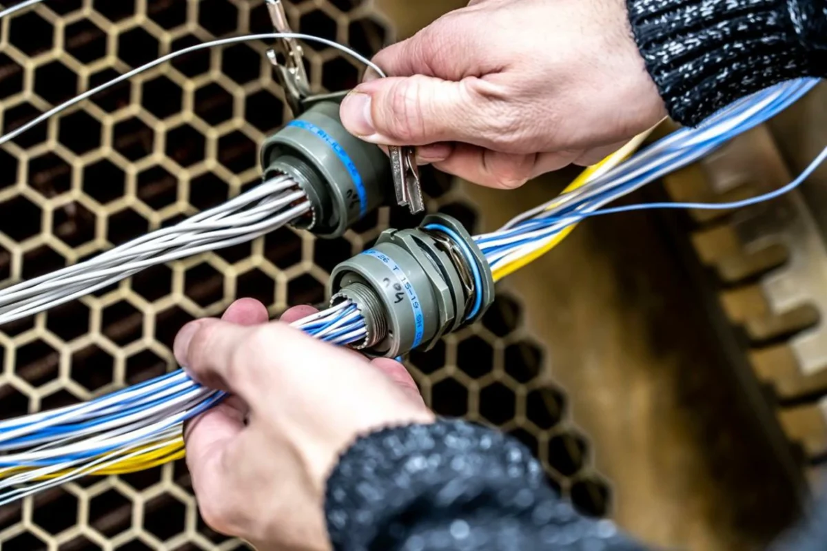
The connector interface consists of two matching parts.
Usually:
- The GX16 connector plug is installed on the cable side.
- The GX16 connector socket is installed on the equipment side.
However, different suppliers may use different naming methods.
Before ordering, customers should confirm the actual mechanical drawing rather than relying only on product names.
Confirm Connector Interface Before Purchasing
For OEM projects, the following information should be included:
| Required Information | Purpose |
| Connector series | Confirm basic structure |
| Plug/socket type | Ensure correct mating |
| Pin count | Match circuit design |
| Mounting size | Match equipment panel |
| Cable direction | Confirm installation space |
GX16 Connector Ordering Verification List
This information reduces repeated communication between the equipment manufacturer and connector supplier.
Why Connector Samples Are Important for Custom Projects
For standard products, a catalog specification may be enough.
For customized cable assemblies, a sample check is usually more effective.
A sample can verify:
- Physical mating
- Cable routing
- Installation position
- Pin sequence
- Assembly method
Especially when the connector is installed inside a compact device, a drawing may not show every mechanical interference problem.
How Do Aviation Connectors Handle Industrial Environments?
Industrial connectors are often installed in places where normal electronic components cannot easily operate.
The actual environment may include:
- Continuous vibration
- Frequent maintenance
- Dust exposure
- Temperature changes
- Outdoor installation
A connector selected only according to electrical specifications may not perform well in these conditions.
Consider Mechanical Stress During Equipment Operation
The locking structure is one of the main reasons circular connectors are used in industrial systems.
Compared with loose-fit connections, threaded locking provides:
- Better retention
- Reduced accidental disconnection
- Stable mating force
This is useful for:
- Automation equipment
- Testing machines
- Moving platforms
- Industrial instruments
Evaluate Cable Protection Together With Connector Selection
Connector reliability is not only determined by the connector body.
The cable connection area also affects service life.
Common considerations include:
- Cable bending radius
- Cable clamp structure
- Pulling force
- Installation direction
A good connector assembly should protect the internal solder joints from mechanical stress.
How Should You Select Aviation Connectors for Different Industrial Environments?
Different working conditions require different connector considerations.
Industrial Environment Decision Matrix
| Working Condition | Main Concern | Recommended Consideration |
| Indoor equipment | Stable connection | Standard circular connector |
| Vibration equipment | Prevent loosening | Thread locking structure |
| Outdoor installation | Moisture protection | Sealing design |
| Frequent maintenance | Easy replacement | Convenient mating structure |
| Compact device | Installation space | Small circular connector |
Industrial Environment Decision Matrix
Do Not Choose Waterproof Connectors Only by Appearance
A waterproof design may look stronger, but selection still depends on the actual application.
Before choosing a waterproof aviation connector, confirm:
- Required protection level
- Cable diameter
- Installation environment
- Maintenance frequency
For example:
An indoor control cabinet may not need a sealed connector.
A sensor installed outdoors may require additional protection.
The correct connector is the one that matches the operating condition.
When Should You Choose a Waterproof Aviation Connector?
Waterproof aviation connectors are mainly considered when equipment is exposed to environmental risks.
Typical applications include:
- Outdoor monitoring equipment
- Industrial sensors
- Mobile machinery
- Automation systems
The decision should be based on the installation environment rather than the product appearance.
Custom Specification and Quality Control Before Delivery
In many connector projects, the first sample is rarely the difficult part.
The challenge usually appears when the product moves from a few prototypes to regular production.
A connector that works on a test bench may still need adjustments before it can be installed into hundreds or thousands of machines.
Typical problems during this stage include:
- Cable length does not match the equipment layout
- Pin sequence is different from the control board
- Connector direction affects installation
- Cable diameter does not fit the clamp
- The connector cannot withstand the actual working environment
This is why industrial customers usually provide more information than just a connector model number.
A request such as “GX16 connector” describes the product family, but it does not define the complete assembly requirement.
A production-ready specification normally includes:
- Connector model
- Pin configuration
- Plug or socket type
- Cable specification
- Cable length
- Wiring sequence
- Application environment
What Information Should Buyers Prepare Before Ordering Aviation Connectors?
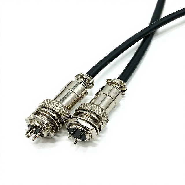
A pair of cable-mounted GX aviation connectors showing male and female interfaces, metal threaded housings, and cable clamps. The matching plug-and-socket design allows industrial devices, control modules, and electrical systems to be disconnected and replaced more efficiently.
A clear specification reduces unnecessary modification after samples are produced.
For standard connectors, the product model may be enough.
For customized aviation connector assemblies, suppliers normally need additional details.
Confirm the Mechanical Interface First
Mechanical compatibility is usually checked before electrical details.
Important points include:
Connector series
Different circular connector series have different mounting sizes.
Examples:
- GX12
- GX16
- GX20
A connector that fits one device may not fit another panel opening.
Plug and socket type
The customer should specify whether the requirement is:
- Cable plug
- Panel socket
- Complete connector set
This is especially important for GX16 projects because the plug and socket may be purchased separately.
A wrong selection may not be discovered until assembly.
Installation direction
Space inside industrial equipment is often limited.
The connector position may affect:
- Cable bending direction
- Maintenance operation
- Equipment enclosure design
For compact devices, connector orientation should be confirmed before production.
How Should GX16 Connector Specifications Be Defined?
The GX16 connector is often selected for compact industrial equipment.
However, the final specification depends on how the connector is used.
A complete GX16 requirement usually includes:
| Specification Item | Customer Confirmation |
| Connector series | GX16 |
| Pin quantity | 2P / 3P / 4P / multi-pin |
| Connector side | Plug / socket |
| Cable type | Required cable specification |
| Cable length | Actual installation distance |
| Wiring sequence | Pin assignment |
| Installation method | Panel or cable connection |
| Application | Equipment working condition |
GX16 Connector Custom Specification Sheet
For example:
A GX16 connector used for a small control box may mainly require:
- Compact size
- Easy installation
- Stable signal connection
A GX16 connector used on industrial equipment may additionally require:
- Strong locking
- Better cable protection
- Repeated mating capability
The connector model may remain the same, but the production requirement changes with the application.
Why Is Sample Verification Important Before Mass Production?
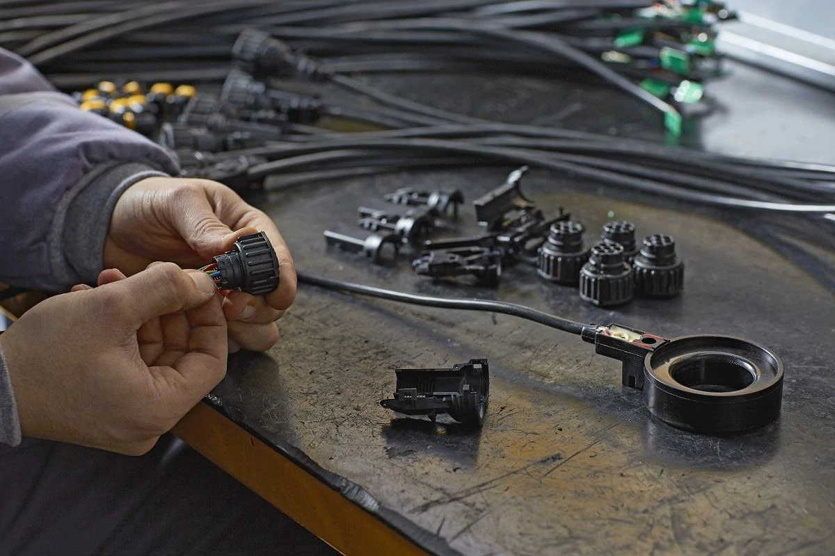
A production worker assembles circular aviation connectors onto industrial cables. Important manufacturing checks include pin sequence, solder joint condition, cable clamping, strain relief, connector mating, continuity testing, and final appearance inspection before delivery.
Many connector problems are easier to solve during sample testing than after delivery.
A sample allows customers to confirm:
- Mechanical fitting
- Cable routing
- Pin arrangement
- Connector operation
- Installation convenience
For customized cable assemblies, sample confirmation is usually a key step before moving into volume production.
Mechanical Assembly Verification
For cable assemblies, the connector and cable should be inspected together.
Important items:
- Cable pulling strength
- Solder joint condition
- Strain relief
- Locking performance
A connector failure is sometimes caused by cable assembly stress rather than the connector body.
Aviation Connector Inspection Checklist
Aviation Connector Quality Inspection Checklist
| Inspection Item | Verification Method |
| Product model | Match order specification |
| Pin number | Visual confirmation |
| Plug/socket type | Mechanical check |
| Appearance | Housing and contact inspection |
| Mating performance | Plug/socket test |
| Pin continuity | Electrical test |
| Contact resistance | Measurement |
| Insulation resistance | Electrical test |
| Cable assembly | Pull and appearance check |
| Final result | Pass / Fail |
Where Are Aviation Connectors Used in Industrial Equipment?
The application of aviation connectors is mainly related to equipment design requirements.
They are often selected when the system needs a removable connection instead of permanent wiring.
Automation Equipment
In automation systems, connectors are frequently used between:
- Controllers
- Sensors
- Motors
- Operation modules
The advantage is easier maintenance.
When one module needs replacement, technicians can disconnect the interface instead of rebuilding the entire wiring system.
FAQ
1. Why does the same aviation connector model have different specifications?
The same connector series can be used in different equipment, but the final specification may change according to the application.
2. What causes problems after installing an aviation connector?
Many connector issues are not caused by the connector body itself. Common problems appear when the interface information is not confirmed before assembly.
Typical situations include reversed pin sequence, incorrect plug and socket matching, unsuitable cable direction, or cable stress affecting solder joints.
