IP67 connector: O-ring sealing, bulkhead install & outdoor RF
Oct 24,2025
Preface

This image serves to guide readers in understanding the importance of IP67 sealing for maintaining VSWR performance and long-term reliability of outdoor RF systems.
Every outdoor RF system—from a base station on a windy rooftop to a vehicle-mounted telemetry unit—depends on how well its connectors resist moisture, vibration, and corrosion. Even with perfect cables and antennas, a single unsealed joint can destroy your VSWR and flood your equipment. That’s where an IP67 connector comes in.
At TEJTE, SMA and N-type series connectors are built not just for signal precision but for long-term sealing. Models like SMA-KE and SMA-KWE combine brass-gold plating, beryllium-bronze sockets, and silicone O-rings (Type 6146) to achieve full IP67 waterproof performance. Rated for DC–6 GHz, Withstand voltage 335 V rms / Operating 50 V DC working voltage, and > 500 mating cycles, they survive extreme temperatures from -65 °C to +165 °C.
If you’re planning an outdoor radio, gateway, or test enclosure, choosing and installing these connectors correctly is what keeps the inside dry and the signals clean.
Which IP67 connector form should you pick for your RF chain?
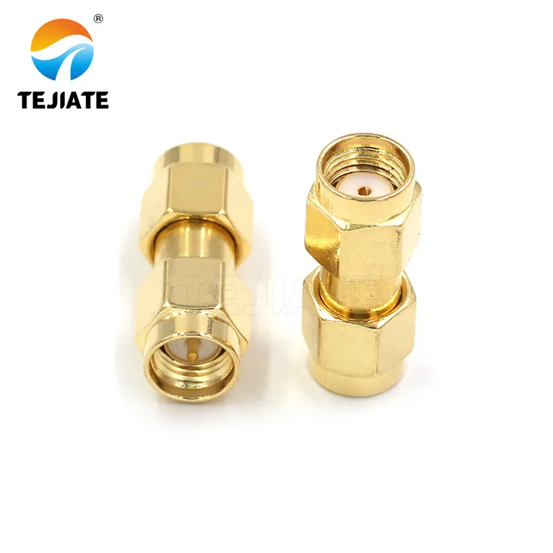
This chart or diagram likely compares key parameters and application scenarios of different IP67 connector models (e.g., SMA-KE, N-type).
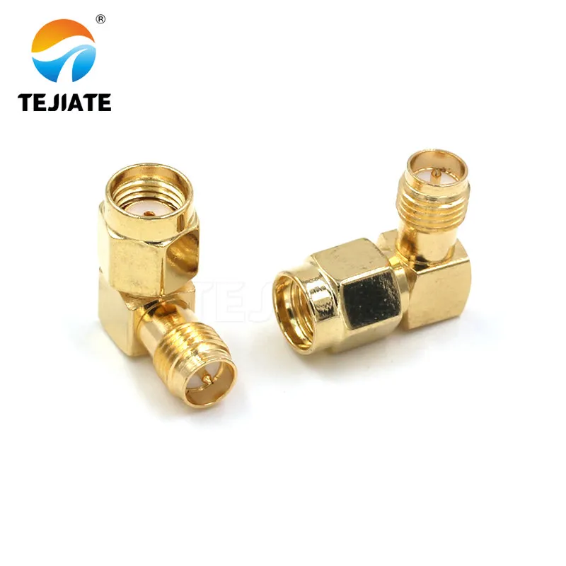
This image details the internal structure and sealing design of an SMA IP67 connector, emphasizing its high-frequency performance and durability.
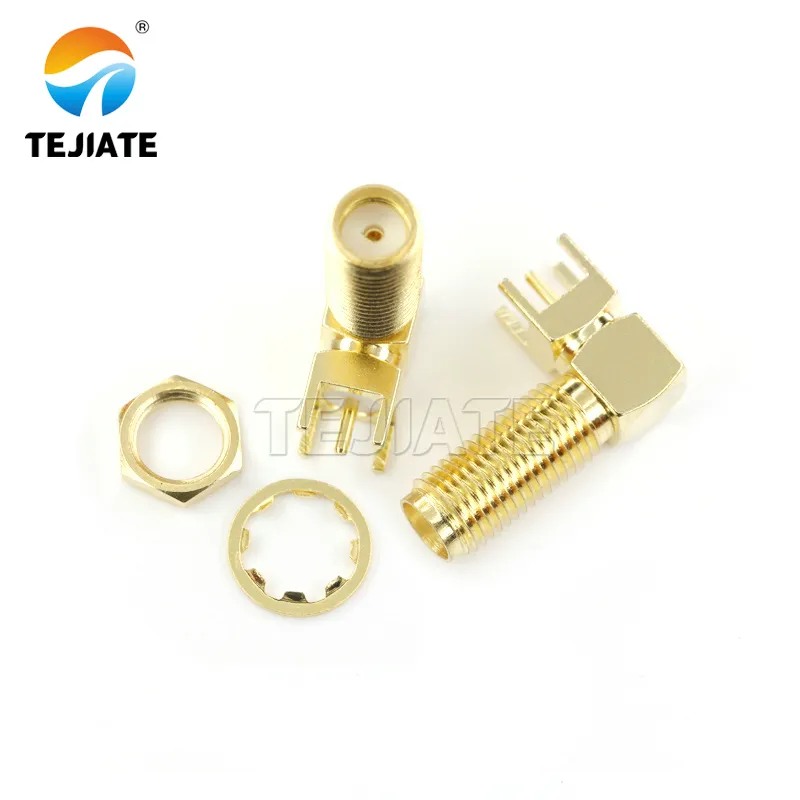
This image illustrates how right-angle connectors optimize cable routing and mechanical stability inside compact equipment.
This chart helps users select the appropriate connector type based on device space constraints and performance requirements (e.g., frequency range, power).
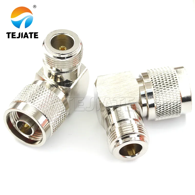
This image highlights the physical construction of the stainless steel right-angle SMA connector. Compared to standard models, the stainless steel material significantly enhances the connector's corrosion resistance and overall durability in harsh environments (e.g., high humidity, salt spray, or industrial settings with chemicals). Its right-angle form factor effectively reduces cable bend stress, enabling optimized routing in confined spaces while maintaining reliable RF performance.
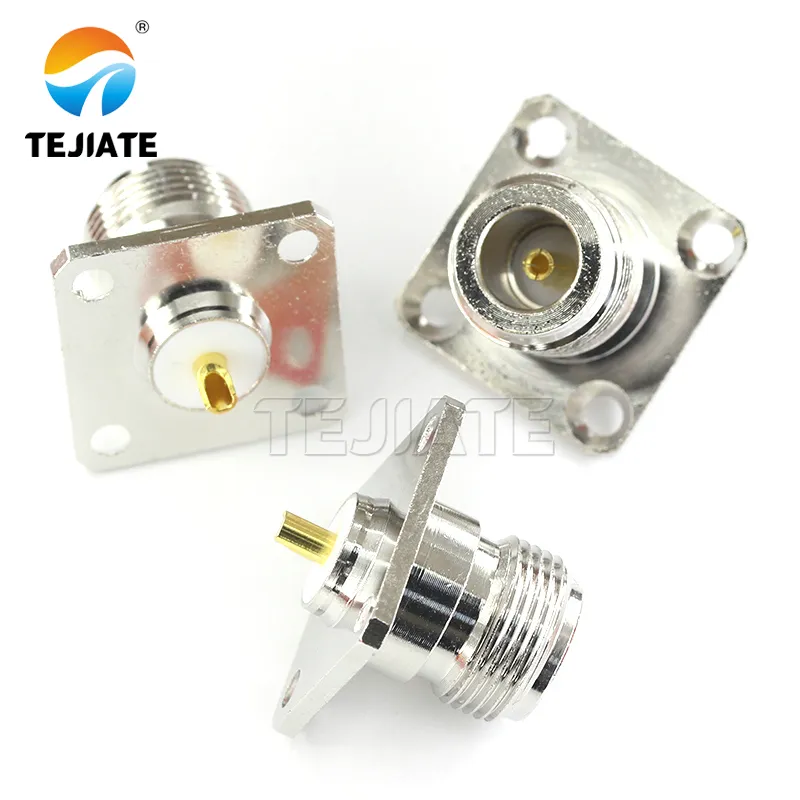
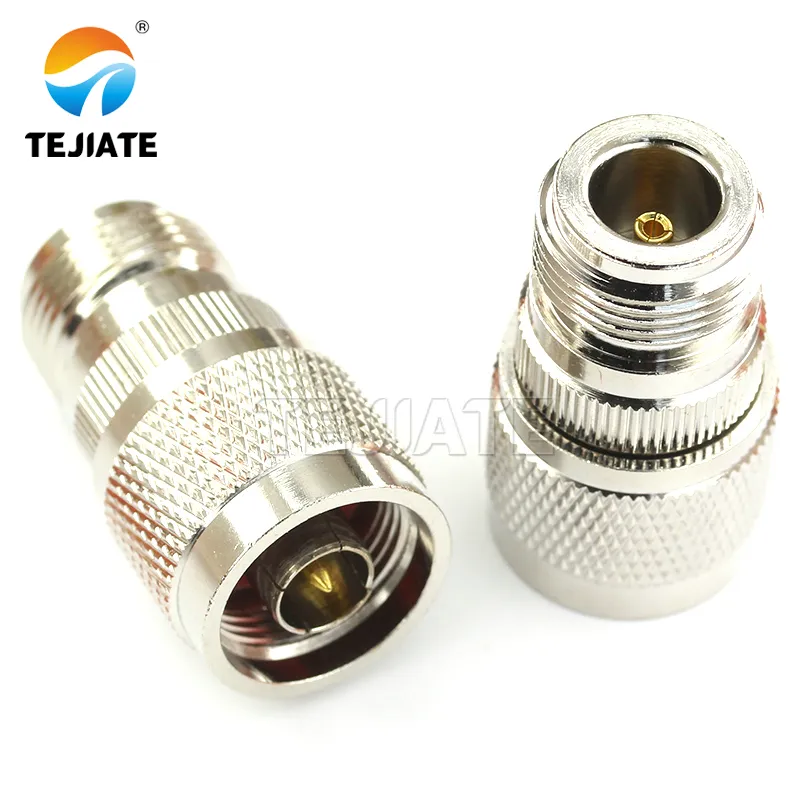
This image highlights the advantages of N-type connectors in outdoor environments requiring higher mechanical strength and power handling capability.
The right connector form determines how easily your RF line stays sealed and mechanically stable. Between SMA and N-type connectors, each brings different strengths to an IP67 build.
For compact IoT radios or 2.4 / 5 / 6 GHz Wi-Fi systems, the SMA connector remains dominant because of its small footprint and 50 Ω precision. A gold-plated SMA-KE bulkhead jack with an 11 mm to 21 mm thread length suits most outdoor housings, while the SMA-KWE right-angle version (19 mm overall) fits enclosures where vertical clearance is limited.
By contrast, N-type connectors are preferred in high-power outdoor repeaters and base antennas where the larger body dissipates heat and offers stronger mechanical torque. For long LMR-240 feeder lines or RG58 jumpers exposed to rain, the N-female bulkhead with silicone boot provides better long-term retention.
The SMA-KKY coupler—a female-to-female adapter with 22.2 mm overall length—is often used to bridge internal panel feedthroughs. Its gold-plated brass housing and matched impedance keep return loss below 0.15 dB @ 6 GHz while the internal O-ring resists capillary water entry.
When routing cables through tight spaces, right-angle or inline forms each serve different purposes. Bulkhead connectors give you a mechanical mounting point; inline ones act as mid-cable junctions; right-angle models relieve strain inside compact PCBs. For example, the SMA-KWE-13 mm type can pass through an 8.5 mm panel hole with a 1.7 mm gasket seat, securing a clean fit for industrial controllers or router housings.
For more on connector series and form factors, see TEJTE’s RF Connectors page.
How do you size thread length and panel hardware for a sealed bulkhead?
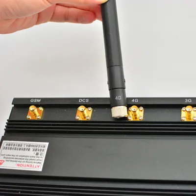
This chart is a key reference tool for ensuring reliable sealing of IP67 connectors on panels of varying thicknesses and materials.
One of the most overlooked details in IP67 design is thread length vs. panel thickness. A mismatch can crush the O-ring or leave a gap that leaks under pressure.
Here’s the rule of thumb used by TEJTE’s engineering team:
- Choose a thread that extends at least 1.5 × pitch beyond the panel after the washer and nut stack.
- Maintain an O-ring squeeze of 15–30% for effective sealing.
- For aluminum panels thicker than 2.5 mm, a 15 mm or 17 mm thread SMA-KE is ideal; for painted steel or plastic walls above 3 mm, the 21 mm version ensures full nut engagement.
All TEJTE SMA bulkheads use 1/4-36 UNS-2A threads, with panel openings typically Ø 6.5 ± 0.1 mm and flat washer seats around Ø 6.8 mm. Pair the connector with a nickel-plated washer and star lock ring to prevent rotation during tightening. The recommended nut torque is 0.6–0.8 N·m, applied using a small SMA wrench.
A practical field tip: always hand-start the nut before wrenching. Cross-threading can tear the plating and compromise both the electrical path and the seal. For mixed-metal interfaces (e.g., brass connector on aluminum panel), apply a thin dielectric grease layer to reduce galvanic corrosion.
When mounting in outdoor telemetry housings or router shells, you’ll often need multiple thread options. TEJTE provides SMA-KE bulkheads in 11 mm, 13 mm, 15 mm, 17 mm, 21 mm, and 23 mm threads, covering both thin PCB enclosures and thick industrial panels.
Related technical insight: N-type Connector Guide: Outdoor Install & IP67 Sealing
Can you reach IP67 with O-rings alone—or do you need boots and heat-shrink?
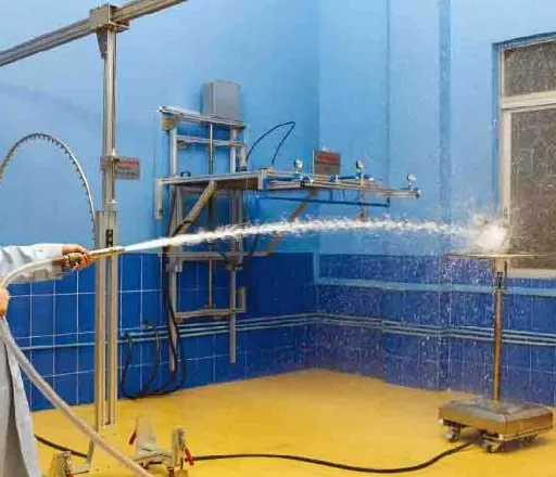
This image provides technicians with a practical field acceptance checking procedure to ensure each IP67 connection is mechanically and electrically sound.
An O-ring is your first line of defense—but never the only one. Even with precision machining, vibration and UV exposure can gradually degrade silicone or nitrile seals. For real outdoor reliability, professional installers combine O-rings, boots, and heat-shrink sleeves to build a multi-layer barrier.
Let’s break down each component:
- O-ring (primary seal): TEJTE’s IP67 SMA connectors use silicone rubber 6146, selected for elasticity and low-temperature flexibility.
- Butyl tape & UV wrap (secondary seal): applied after tightening to protect the nut area from sun and water pooling.
- Boot or heat-shrink (tertiary seal): anchors the cable jacket and stops wicking along the braid.
Will an SMA extension cable or adapter stack break your seal budget?
Every extra joint in an RF line is a new leak path. Stacking SMA to SMA adapters might seem convenient, but each interface adds two potential failure points—one mechanical, one electrical. In outdoor builds, that’s how an IP67 rating quickly downgrades to IP50.
If you need to extend a cable, it’s safer to swap stacked adapters for a short jumper cable with molded boots. A pre-terminated SMA extension cable such as LMR-240 SMA-SMA male-to-female gives the same functionality while keeping one continuous seal. The low-loss 50-ohm coax cable core maintains impedance integrity and eliminates micro-gaps that trap moisture.
For compact devices, RG58 or RG316 jumpers remain practical. TEJTE’s RG316 assemblies rated up to 6 GHz use crimped gold-plated SMA connectors with factory-applied silicone boots. For longer outdoor feeders or antenna masts, LMR-240 or LMR-400 cables are more robust, offering attenuation as low as 0.22 dB/m @ 2.4 GHz and a bend radius of 25 mm.
Stacking metal-to-metal adapters also introduces small impedance discontinuities. Each adds about 0.05 dB of mismatch loss and slight VSWR ripple. Over time, thermal cycling loosens the threads, compromising both RF performance and sealing torque.
A simple field recommendation: keep no more than one connector pair per panel wall. Replace double-female couplers like SMA-KKY with custom-length pigtails—available from TEJTE’s RF Cable Assemblies page. You’ll save insertion loss, maintain full IP67 sealing, and simplify installation checks.
How do you route and support cables for long-life IP67 installs?
Even a perfectly sealed IP67 connector can fail early if the cable behind it is poorly routed. Strain, UV, and vibration gradually pull the joint apart. In field tests, most “leaks” originate not from the O-ring but from stress at the cable entry.
To prevent this, follow three principles:
- Gravity control – add drip loops.
Route the coax downward before it enters an enclosure so rainwater drips off rather than flowing into the connector.
- Mechanical relief – use clamps and anchors.
UV-rated cable ties or P-clamps every 30 cm stop whip movement in windy masts. Pair them with vibration-resistant washers under bulkheads.
- Torque management – set and re-check.
Apply 0.6–0.8 N·m to SMA bulkhead nuts, 1.2–1.5 N·m to N-type. Re-torque every six months for equipment exposed to temperature cycling.
Cables such as LMR-240 offer a perfect balance of flexibility and shielding. Its closed-cell PE dielectric prevents water migration, while the bonded foil resists cracking when bent repeatedly. For compact routers or Wi-Fi gateways, RG316 remains a lightweight alternative, especially when paired with SMA-KWE right-angle connectors to relieve pull stress.
Inside panels, anti-rotation tabs on SMA-KE bulkheads keep the connector body from spinning under torque. Adding a star washer between nut and panel distributes pressure evenly, preserving O-ring compression.
An installer’s tip: if your device vibrates—such as in vehicles or industrial robots—secure the jumper near the connector using a foam spacer or flexible boot. It dramatically extends the life of the crimp joint.
For detailed examples of outdoor cable routing and UV protection, TEJTE’s LMR-240 Guide: Loss, Bend & Outdoor Routing shows how different bend radii affect long-term attenuation.
Can you verify “sealed & in-spec” without lab gear?
You don’t need a full RF bench to confirm whether an IP67 connector installation is sound. A few quick checks can tell you if your system is both sealed and electrically intact.
- Continuity test.
Use a handheld multimeter to verify the center pin and shield continuity. Resistance should read < 5 mΩ (inner) / < 2 mΩ (outer) for models like SMA-KE or SMA-KKF.
- Spot return-loss check.
A compact VSWR meter at 2.4 GHz reveals mismatches from cross-threading or loose torque. Expect ≤ 1.10:1 VSWR if the joint is correctly sealed and tightened.
- Visual seal inspection.
Ensure the silicone O-ring (TEJTE Type 6146) is evenly compressed—no pinches, no visible metal between washer and nut.
- Field leak-check.
Wipe around the joint with an absorbent swab, then spray a fine water mist. If the swab stays dry after 30 seconds, the enclosure passes a practical IP67 verification.
- Simulated rain or hose test.
For production enclosures, angle the spray 15° for 3 minutes at 100 kPa pressure, similar to IEC 60529. Inspect after disassembly—any moisture trace near the braid indicates insufficient torque or damaged O-ring.
These simple routines let technicians certify a sealed installation without a lab. Combined with accurate torque and proper cable support, your assembly maintains both mechanical integrity and RF performance.
To cross-check sealing criteria, refer to TEJTE’s RF Connector Maintenance Tips.
Order once: which IP67 connector + cable combo fits your site?
| Port Type | Panel Thread / Thickness | Thread Length (mm) | Seal Kit | Cable Type | Min. Bend Radius | Est. Loss (dB/m) | Torque (N·m) | Suggested TEJTE P/N |
|---|---|---|---|---|---|---|---|---|
| SMA-KE (female bulkhead) | Aluminum 2 mm | 11/13 | O-ring 6.5×1.5, boot=Y | RG316 | 15 mm | 0.45 @ 2.4 GHz | 0.6-0.8 | 08831 / 08833 |
| SMA-KE (female bulkhead) | Painted steel 3 mm | 15/17 | O-ring 6.8×1.7, boot=Y | RG58 | 25 mm | 0.27 @ 2.4 GHz | 0.6-0.8 | 08833 / 08835 |
| SMA-KE (female bulkhead) | Thick panel ≥5 mm | 21/23 | O-ring 6.8×1.7, boot=N | LMR-240 | 25 mm | 0.22 @ 2.4 GHz | 0.8 | 08833 (21 mm) |
| SMA-KWE (female right-angle) | PCB / router shell | 13 | O-ring 6.5×1.5, heat-shrink=Y | RG316 | 10 mm | 0.45 @ 2.4 GHz | 0.6 | 08841 |
| SMA-KKY (female-female coupler) | Panel feedthrough | 17.7 ± 0.1 | O-ring 5.8×0.1, grease=Y | — | — | <0.15 @ 6 GHz | 0.6 | 49485 |
| SMA-KKF (flange, outdoor waterproof) | 18G flange wall | 18G flange | O-ring 6.6×1.5, boot=Y | RG58 / LMR-240 | 25 mm | 0.25 @ 2.4 GHz | 0.8 | 64173 |
| N-type (female bulkhead) | Steel 4 mm | 21–33 | O-ring 8×2.0, boot=Y | LMR-400 | 50 mm | 0.17 @ 2.4 GHz | 1.2-1.5 | — |
These parameters ensure full sealing margin under outdoor exposure, vibration, and salt-fog conditions. Most assemblies are RoHS-compliant, rated 50 Ω, 1 A current, and designed for 0–18 GHz continuous operation.
A good installation practice: once you select a connector thread and cable pair, order all parts together—including matching O-rings, boots, and torque tools—to guarantee consistent sealing. You can find compatible configurations on TEJTE’s RF Connector Series overview.
Will your enclosure pass an IP67 checklist before shipping?
| Category | Criterion | Result Standard |
|---|---|---|
| Dimensions | Thread engagement ≥ 1.5 × pitch | Nut flush, 1-2 visible threads |
| O-ring squeeze 15-30 % | Visible uniform compression | |
| Materials | Compatible plating (brass/aluminum) | No galvanic reaction, grease applied |
| Non-conductive gasket used if mixed metals | Pass | |
| Assembly | Nut hand-started, torque to spec | 0.6-0.8 N·m (SMA), 1.2-1.5 N·m (N-type) |
| No connector twist during torque | Cable strain relief verified | |
| Boot / heat-shrink applied | Complete coverage, no gaps | |
| Verification | Continuity OK | Inner ≤ 5 mΩ / Outer ≤ 2 mΩ |
| No braid exposure / no cracks | Pass | |
| O-ring intact, no nicks | Pass | |
| Verification | Water spray test (IEC 60529, 3 min @ 100 kPa) | Swab remains dry |
Passing all items means your enclosure will survive heavy rain or even temporary immersion without degrading VSWR or insulation resistance. It also ensures mechanical robustness for >500 cycles of mating and unmating—critical for test instruments and outdoor routers.
One practical inspection trick: mark the nut position with a paint dot after torque. If the dot shifts over time, you’ll instantly see if vibration loosened the connector.
Frequently Asked Questions
1. Do O-rings alone make an RF connector IP67, or do I also need boots and heat-shrink?
Not always. An O-ring provides point sealing only at the bulkhead. For long-term outdoor use, you still need secondary barriers like UV tape or boots to stop capillary wicking. Most TEJTE SMA-KKE and SMA-KKY designs include both O-rings and thread-seated washers for redundancy.
2. How much thread engagement and torque should I target on an IP67 bulkhead?
For SMA connectors, aim for 1.5× thread engagement and torque of 0.6–0.8 N·m. N-type connectors tolerate more torque (1.2–1.5 N·m). Use a small torque wrench—hand-tight is never repeatable.
3. Will stacking SMA adapters compromise the seal or VSWR compared with a short jumper?
Yes. Each added SMA to SMA adapter introduces microgaps that weaken the O-ring compression and slightly disturb impedance. Replace stacks with short, molded jumpers such as LMR-240 SMA extension cables for consistent IP67 protection.
4. Which cable (LMR-240 vs RG58 vs RG316) holds up best outdoors with IP67 ends?
LMR-240 offers the best UV and moisture resistance; RG58 is moderate; RG316 is most flexible but less UV-stable. For rooftop or pole installations, LMR-240 with SMA-KE bulkhead connectors ensures lower loss and stronger sealing.
5. How do I prevent corrosion on aluminum panels when using nickel- or gold-plated connectors?
Apply a thin dielectric grease film between the panel and connector nut. TEJTE’s O-ring kits use non-conductive gaskets that prevent galvanic corrosion between brass and aluminum surfaces.
6. What quick tests confirm an enclosure is sealed after installation?
Perform a continuity check (<5 mΩ), a visual O-ring inspection, and a 30-second mist test. If the surface stays dry, your IP67 connector is ready for field deployment. For full procedures, see TEJTE’s RF Connector Install & Waterproof Guide.
Wrap-up
Selecting and installing IP67 connectors is less about luck and more about precision. With the right combination of SMA bulkheads, waterproof couplers, and low-loss coax cables, even small enclosures can achieve military-grade sealing.
TEJTE’s verified components—SMA-KE, SMA-KWE, SMA-KKY, SMA-KKF—deliver dependable results across industries: network communication, avionics, measurement, and medical devices. When each nut, washer, and O-ring fits as intended, your RF path stays sealed, your signal stays clean, and your system stays online—rain or shine.
Bonfon Office Building, Longgang District, Shenzhen City, Guangdong Province, China

A China-based OEM/ODM RF communications supplier
Table of Contents
Owning your OEM/ODM/Private Label for Electronic Devices andComponents is now easier than ever.
