
A cable can pass a continuity test and still be the wrong communication cable for an RF signal path.
That is where many sourcing problems begin. The drawing says “cable.” The buyer searches for a communication cable. The supplier asks for length and connector type. A sample is built, it lights up the device, and nobody notices the RF weakness until the antenna range test, GPS lock test, WiFi throughput check, or VNA sweep shows a problem.
For RF and wireless devices, the cable is not only a piece of wire between two points. It is part of the signal path. Its impedance, shielding, connector interface, cable loss, routing, bend radius, and termination quality all affect the final result. A short internal antenna jumper, a 1 m SMA cable, and a longer outdoor antenna lead may all be called communication cables, but they should not be purchased with the same level of detail.
This guide focuses on communication cable selection for RF modules, antennas, wireless terminals, GPS devices, WiFi equipment, test setups, and similar signal transmission applications.
How Do Communication Cables Carry RF and Device Signals?
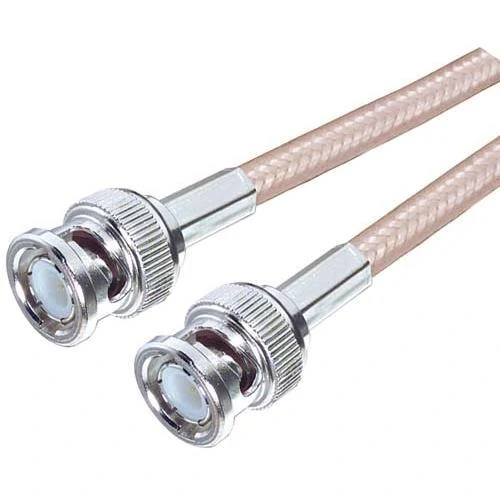
BNC RF cable assembly designed for stable signal transmission in communication systems, RF testing equipment, and electronic applications. The coaxial cable structure helps maintain impedance control and shielding performance.
A communication cable carries information from one point to another. In RF work, that information may be a high-frequency signal between a module and antenna, a test signal between equipment and a device under test, or a low-power signal inside a compact wireless product.
The problem is that “communication cable” is a broad term. It may refer to coaxial cable, shielded cable, antenna cable, RF cable assembly, twisted pair cable, or device-level wiring. For TEJTE-style RF sourcing, the useful question is not “Do you have a communication cable?” The useful question is: What signal is the cable carrying, at what frequency, through which connectors, and under what installation condition?
For many antenna and RF applications, coaxial cable is used because its structure helps control impedance and shielding. The center conductor carries the signal. The dielectric separates the center conductor from the shield. The shield helps reduce unwanted interference and provides the return path. The outer jacket protects the cable mechanically.
That structure matters. A general wire may conduct electricity, but it does not provide the same controlled signal environment as a coaxial RF cable. At low frequency or for simple device wiring, that may be acceptable. At WiFi, GPS, LTE, RF test, or microwave frequencies, it can become a real failure point.
A cable assembly may look fine from the outside. The connectors may mate. The device may power on. But the RF path may still have high insertion loss, poor return loss, unstable VSWR, or inconsistent performance after bending.
Explain the role of communication cables in signal transmission
In RF and wireless equipment, communication cables normally connect one of these paths:
| Signal Path | Cable Focus | Common Application |
| RF module to antenna | Impedance + connector matching | WiFi, GPS, IoT terminals |
| Device to test equipment | Signal stability | RF testing, lab measurement |
| Enclosure to external antenna | Shielding + routing | Wireless terminal, gateway |
| Internal device wiring | Flexibility + cable size | Compact electronics |
| Long antenna run | Low cable loss | Communication system, outdoor antenna |
This table is simple, but it prevents a common mistake. Buyers often specify the connector but forget the signal path. An SMA connector on a short RG316 jumper does not solve the same problem as an N-type connector on a low-loss antenna cable. The connector name alone is not enough.
A better RFQ should describe the signal path first. For example:
“SMA male to U.FL cable assembly, 50 ohm, 100 mm, for internal WiFi antenna connection.”
That is much clearer than:
“SMA communication cable.”
Identify RF, antenna, wireless, and device-level signal paths
Different communication cable applications have different risks.
A GPS antenna cable is often sensitive to loss because the received signal is weak. A WiFi antenna cable may need compact routing, small connectors, and stable performance through repeated assembly handling. A test cable may need better phase and amplitude stability than a normal production jumper. A cable inside a metal enclosure may need careful routing so the connector is not carrying mechanical stress.
The same cable type can behave differently depending on length. A short 100 mm mini coax jumper may have acceptable loss for an embedded module. Stretch that path to 1 m or 3 m, and cable attenuation becomes harder to ignore. At higher frequencies, the cable may become the bottleneck before the connector rating does.
This is also why “low loss RF cable” should not be treated as a decorative phrase. It is useful when the cable run is long enough for attenuation to matter. For very short internal cables, flexibility, connector height, cable outer diameter, and assembly consistency may be more important than chasing the lowest possible loss.
Separate communication cables from power cables and general wires
Power cables are usually specified around voltage, current, insulation, conductor size, temperature, and safety margin. RF communication cables need different information.
For RF use, the buyer should confirm:
- impedance, usually 50 ohm for many RF systems;
- frequency range;
- cable attenuation;
- shielding structure;
- connector type and gender;
- cable length;
- routing space and bend radius;
- test requirements such as continuity, VSWR, or insertion loss.
A general wire may be acceptable for low-speed control signals. It is not a safe substitute for an RF antenna cable unless the application has been tested and approved.
One small wording issue can create a big production issue. If the BOM only says “communication cable, SMA, 300 mm,” a supplier may quote a cable that fits the connector but not the frequency, shielding, or loss requirement. The first sample may still appear usable. The failure shows up when the customer changes antenna location, increases cable length, or routes the cable near a noisy power section.
How Should You Separate RF, Antenna, and Data Cable Needs?
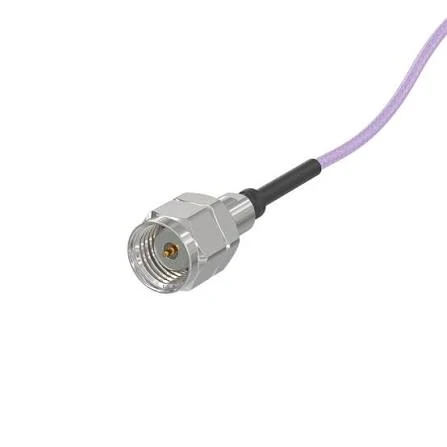
SMA RF communication cable assembly featuring coaxial cable construction and SMA connectors. Suitable for WiFi, GPS, IoT modules, and RF signal transmission applications requiring stable connectivity.
A practical sourcing rule: do not start with the broad cable category. Start with the signal.
If the cable carries RF energy between a transmitter, receiver, antenna, filter, amplifier, splitter, or test instrument, treat it as an RF cable or RF cable assembly. If the cable ends at an antenna, treat it as an antenna cable and confirm the connector on both the device side and antenna side. If the cable is used for digital data, control, or communication between boards, the selection logic may be different.
The word “communication” can hide too many details. It may mean wireless signal, serial data, Ethernet, control wiring, shielded sensor wiring, or coaxial antenna feed. A supplier cannot safely select the cable from that word alone.
Select RF cables when frequency control is critical
Use RF cable when the operating frequency, impedance match, and signal loss matter. Typical examples include RF modules, VNA test leads, RF switches, signal generators, antennas, receivers, and communication equipment.
In these cases, the cable should usually be specified as a cable assembly, not only as raw cable. The assembly includes the cable, both connectors, termination process, and inspection requirement. A well-matched RF cable assembly is more than two connectors attached to a cable.
For example, an RG316 SMA cable may be suitable for many compact RF jumper applications. But if the run becomes longer, or the frequency moves higher, the same cable may add too much loss. A buyer may then compare RG58, RG142, LMR-type low-loss cable, or another coaxial cable family depending on flexibility, outer diameter, attenuation, and connector compatibility.
A connector rated for a high frequency does not make the entire cable assembly suitable for that frequency. The cable type, termination quality, connector geometry, and bend condition still matter.
Select antenna cables when the signal path ends at an antenna
An antenna cable is usually part of the RF path, but its selection has some practical differences.
Antenna cable buyers often care about connector style, cable length, waterproofing, panel mounting, and routing. For outdoor antennas, the jacket and sealing method may matter. For embedded antennas, small cable diameter and low-profile connectors may matter more.
Common antenna cable descriptions include:
- SMA antenna cable;
- coax antenna cable;
- WiFi antenna cable;
- GPS antenna cable;
- RF antenna cable;
- N-type antenna cable;
- U.FL to SMA antenna cable.
Each one still needs more detail before production. “SMA antenna cable” should be expanded into gender, polarity, cable type, length, impedance, and application. SMA standard polarity and RP-SMA should not be mixed. A product photo alone can easily cause confusion because the thread direction, center pin, and socket structure must all be confirmed.
Select shielded cables when interference protection matters
Shielding is not only a selling point. It is a design control.
A shielded cable is useful when the cable runs near motors, power wiring, switching supplies, RF transmitters, metal enclosures, or sensitive receive paths. In coaxial RF cables, the shield also supports the controlled transmission structure. In other communication cables, shielding may be selected mainly for EMI protection.
The buyer should not simply ask for “good shielding.” That phrase is too vague. Better wording would be:
“Shielded 50 ohm coaxial cable assembly for RF antenna connection, routed inside a metal enclosure near a power module.”
Now the supplier can think about the actual risk: EMI exposure, cable bend, connector stress, grounding, and shielding continuity.
Avoid using “communication cable” as a vague purchase term
A clear purchase request reduces back-and-forth and lowers the chance of receiving a cable that is electrically functional but technically wrong.
A useful communication cable RFQ should include:
| RFQ Item | Better Specification Example |
| Application | WiFi antenna, GPS module, RF test, IoT terminal |
| Signal type | RF, antenna, data, control, sensor |
| Impedance | 50 ohm or 75 ohm |
| Frequency range | DC–3 GHz, DC–6 GHz, or target band |
| Cable type | RG316, RG58, 1.13 mm mini coax, low-loss coax |
| Connector A | SMA male, U.FL, BNC male, N female |
| Connector B | Same or different interface |
| Length | 100 mm, 300 mm, 1 m, custom length |
| Shielding | Standard coax shield, double shield, special requirement |
| Test requirement | Continuity, VSWR, insertion loss, VNA sweep if needed |
The more specific RFQ saves time for both sides. It also protects the buyer when the part moves from sample to batch production.
A cable that works on the bench may fail after installation. That is usually not because the word “communication cable” was wrong. It is because the specification behind the word was incomplete.
How Do Shielding and Impedance Control Signal Quality?
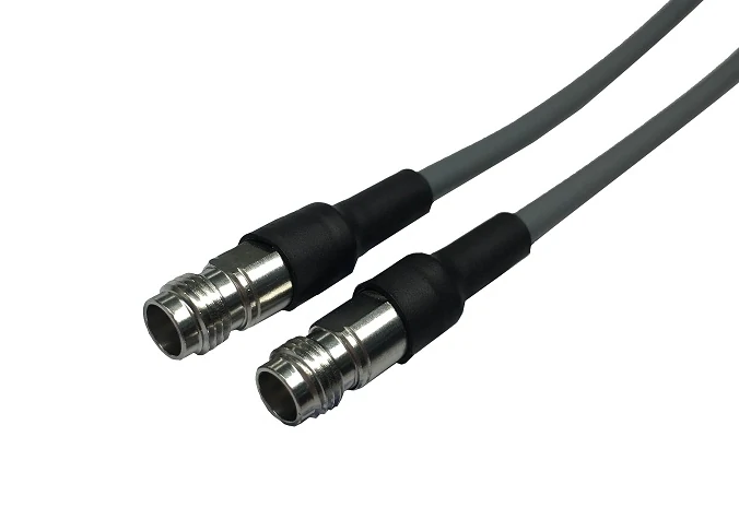
TNC RF communication cable featuring threaded coaxial connectors for secure signal transmission. Suitable for antenna systems, wireless devices, and RF applications requiring mechanical stability.
A communication cable used in an RF path is not only judged by whether it conducts. The harder question is whether it keeps the signal environment stable enough for the device, antenna, or test setup.
Two details decide much of that stability: impedance and shielding.
For many RF communication systems, 50 ohm impedance is the normal starting point. The cable, connector, adapter, antenna port, module port, and test equipment should all be treated as one connected path. If one part is mismatched, the signal may reflect. That reflection can show up as poor VSWR, reduced transmitted power, unstable receive sensitivity, or inconsistent test data.
A cable can also lose performance because of poor shielding. This is common in compact wireless products where the cable is routed close to power circuits, motors, switching supplies, displays, metal frames, or other RF sections. The cable may be electrically continuous, but the signal path is still exposed to noise or unwanted coupling.
Match 50 ohm cable paths with RF communication systems
A 50 ohm cable should not be selected only by cable marking. The full assembly must remain close to the intended impedance through the connector body, center pin, dielectric, crimp sleeve, solder joint, and cable transition.
This is where low-cost substitutions often create hidden problems. A connector may screw on correctly, but its rear body may not match the cable diameter. The ferrule may crimp, but not hold the braid evenly. The center pin may solder, but the dielectric can be overheated or pushed out of position. These small mechanical errors can become RF errors at higher frequency.
For buyers, the safest wording is not “50 ohm SMA cable.” A better BOM note would be:
SMA male to SMA male RF cable assembly, 50 ohm, RG316, 1 m, target frequency DC–3 GHz, continuity tested, VSWR check if required.
That description gives the supplier enough information to select a compatible cable, connector, and inspection method.
Use shielding to reduce EMI and unwanted noise
Shielding should be matched to the installation environment. A short internal cable inside a clean RF layout may not need the same cable structure as a longer antenna cable routed through an industrial enclosure.
The risk increases when the cable passes near high-current traces, motors, power modules, relays, LCD backlight circuits, or other wireless transmitters. In these cases, shielding is not only about the cable specification. Routing also matters. A well-shielded cable can still perform poorly if it is sharply bent near the connector, squeezed under a cover, or forced to carry mechanical tension.
A practical selection matrix helps avoid vague sourcing language:
| Requirement | Recommended Cable Direction |
| RF communication path | 50 ohm RF cable |
| Antenna connection | Coax antenna cable |
| WiFi or GPS device | Mini coax or SMA antenna cable |
| Noisy installation area | Shielded cable |
| Longer signal path | Low loss RF cable |
| Test setup | RF cable assembly with defined inspection |
This matrix does not replace a datasheet. It helps the buyer ask the right first question. Once the signal path is clear, the supplier can confirm cable family, connector type, shielding level, length, and test requirement.
How Can Cable Loss Be Estimated Before Installation?
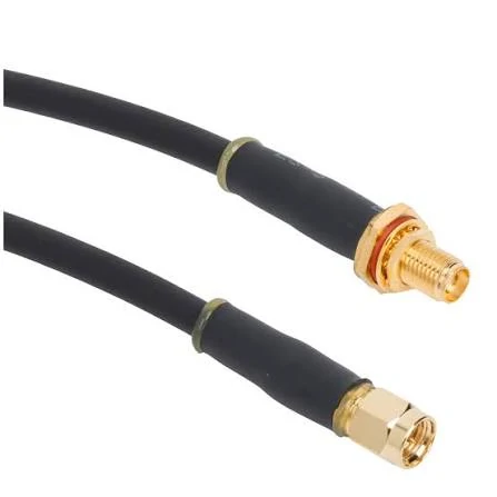
RF coaxial cable assembly designed for wireless communication applications. The cable provides controlled impedance, shielding, and reliable signal transmission between RF components.
Cable loss is easy to ignore when the sample is short. It becomes harder to ignore when the cable length increases, the frequency rises, or the antenna is moved away from the main board.
For RF communication cables, attenuation depends on cable type, operating frequency, and cable length. A small coaxial cable may be flexible and easy to route, but it usually has higher loss than a larger low-loss cable. That trade-off is normal. The mistake is pretending the cable diameter does not matter.
A WiFi device with a 100 mm internal antenna jumper may work well with a small flexible cable. A 2 m antenna extension for the same frequency may need a lower-loss cable. The connector may remain SMA, but the cable choice should change.
This is not a replacement for VNA testing. It is a sourcing filter. If the estimated loss is already too high on paper, the buyer should not wait for a failed field test to change cable type.
Add connector and adapter loss for complete signal paths
Connector and adapter loss is often small compared with a long cable, but it should not be ignored. Adapter stacks are especially risky because each interface adds another mechanical and electrical transition.
A common field problem looks like this: the original device had one short antenna cable. During installation, the customer adds an adapter, then an extension cable, then another adapter because the antenna connector is different from the device connector. The system still connects physically, but the RF path is now longer and less controlled.
For stable sourcing, try to build the required connector combination directly into the cable assembly. For example, instead of using SMA-to-SMA cable plus a separate N-type adapter, specify an SMA male to N female cable assembly if that is the real installation need.
How Should Connectors Be Matched for Communication Cable Assemblies?
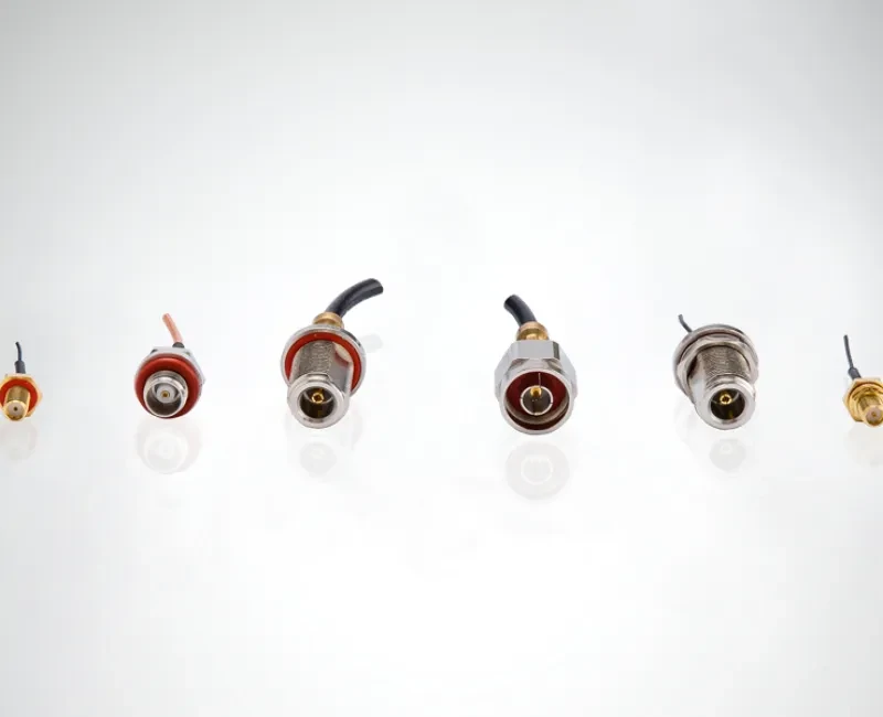
Various RF connector interfaces used in communication cable assemblies. Connector selection depends on frequency range, impedance, installation method, and application requirements.
The connector is the most visible part of a communication cable assembly, so buyers often focus on it first. That is understandable, but incomplete.
Connector matching should include interface, gender, polarity, impedance, mounting style, cable compatibility, and frequency range. For RF paths, the rear side of the connector is just as important as the mating side. A connector designed for RG316 should not be casually substituted with one meant for RG58 or RG142. The cable outer diameter, dielectric size, braid structure, ferrule, and center contact all need to match.
Match SMA connectors with compact RF and wireless modules
SMA connectors are common in WiFi, GPS, IoT, RF modules, test boards, and antenna ports. They are useful because they are compact and widely available. Still, SMA is not one universal part.
Before ordering an SMA communication cable, confirm whether the interface is standard SMA or RP-SMA. Then confirm male or female, straight or right-angle, panel mount or cable end, and the cable type behind the connector.
A product photo can cause mistakes. For RF connectors, thread direction and center contact must both be checked. “Looks like SMA” is not enough for production.
Confirm connector gender, impedance, and mounting style before production
Use this checklist before confirming samples:
| Check Item | Requirement |
| Connector A | SMA / BNC / N Type / TNC / U.FL |
| Connector B | Same or different RF connector |
| Gender | Male / Female |
| Polarity | Standard / Reverse polarity |
| Impedance | 50 ohm / 75 ohm |
| Cable Type | Coax / shielded / low loss |
| Mounting | Cable end / bulkhead / panel |
| Application | Antenna / test / device |
| RF Test | Optional or required |
The final cable should be specified as an assembly, not as separate loose parts unless the customer will terminate it in-house. For custom production, drawings or clear photos are useful, but they should not replace the electrical requirements.
A good RF communication cable request tells the supplier what the cable must do, not only what it should look like.
How Do WiFi, GPS, and Antenna Devices Use Communication Cables?
WiFi, GPS, LTE, IoT, and other wireless devices often use communication cables in places where the cable looks minor but affects the final signal result.
A short antenna jumper inside a router is not the same as a long outdoor antenna extension. A GPS antenna cable is not selected the same way as a general control wire. A WiFi antenna cable may need a small connector and flexible routing, but it still needs proper impedance, shielding, and connector matching.
For compact wireless devices, the first limit is often space. The cable may need to bend around a PCB, pass through a small enclosure, or connect to a low-profile antenna port. In that situation, a thin coaxial cable may be easier to install than a larger low-loss cable. The trade-off is higher attenuation, especially as frequency and length increase.
Use WiFi antenna cables for routers, gateways, and wireless modules
WiFi antenna cables are common in routers, gateways, embedded wireless modules, access points, and industrial IoT terminals. Common combinations include U.FL to SMA, IPEX to SMA, RP-SMA to mini coax, or SMA cable assemblies for external antenna ports.
The important detail is not only the WiFi band. The buyer should confirm whether the device uses standard SMA or RP-SMA, the cable length, the cable diameter, and whether the assembly needs panel mounting. A wrong polarity connector can look almost correct in a product photo but fail during installation.
For 2.4 GHz and 5 GHz WiFi applications, cable length should be kept reasonable. A short internal jumper usually creates less loss than a long antenna extension. If the antenna must be moved farther away from the device, a larger low-loss coax may be safer than a very thin mini coax.
Use GPS antenna cables for tracking and navigation devices
GPS antenna connections are often sensitive because the received signal is weak. A cable with excessive loss, poor shielding, or unstable connector contact may cause slower positioning, weak reception, or intermittent signal problems.
If the cable is routed near power circuits, motors, displays, or metal structures, shielding and routing become more important.
A small GPS antenna cable may work well in a short internal path. For vehicle, outdoor, or enclosure-mounted antennas, the cable may need better mechanical protection and more careful connector selection.
Use coax antenna cables for RF antenna connections
Coax antenna cable is the normal direction for many RF antenna paths because it helps maintain a controlled signal structure. The correct cable depends on frequency, length, connector, flexibility, and installation environment.
| Application | Common Cable Direction | Main Risk |
| Internal WiFi antenna | Mini coax / U.FL cable | Small connector damage, bend stress |
| GPS module antenna | Shielded coax antenna cable | Signal loss, EMI exposure |
| External antenna port | SMA / RP-SMA cable assembly | Wrong polarity or panel style |
| Outdoor antenna run | Low loss coaxial cable | Attenuation, jacket, waterproofing |
| RF lab connection | Tested RF cable assembly | VSWR, insertion loss, repeatability |
The table is not a fixed rule. It is a way to separate cable needs before quoting. A buyer who provides the application and risk point will usually get a better cable recommendation than a buyer who only sends a connector name.
How Should Communication Cables Be Routed and Protected?
A correct cable can fail after installation if the routing is poor.
Sharp bends near the connector, pulling force on the cable exit, compressed cable under a cover, and repeated movement can all damage the RF path. The failure may not appear immediately. The first unit may pass. Later units may show unstable signal, intermittent contact, or worse RF test results after assembly.
Plan bend radius before confirming cable length
Cable length should not be calculated as a straight-line distance only. The cable must follow the real route inside the device or installation area. If the route includes bends, panel exits, hinges, or strain relief, the length should include those conditions.
Too short a cable creates tension. Too long a cable creates folding, crowding, and unnecessary loss. For RF assemblies, both mistakes are common.
Protect connectors and cable exits from mechanical stress
The connector-cable transition is one of the weakest areas. If the cable is pulled, twisted, or bent tightly at the rear of the connector, the braid, solder joint, crimp area, or dielectric may be affected.
It cannot prove high-frequency performance. For sensitive RF paths, electrical testing should be defined before shipment.
How Do You Specify Communication Cables for RFQs and Samples?
A good RFQ prevents the supplier from guessing. It also prevents the buyer from approving a sample that cannot be repeated in production.
For RF communication cables, provide the application first. Then provide the cable type, connector details, impedance, length, frequency range, and test requirement.
| RFQ Field | Example |
| Application | WiFi, GPS, RF module, antenna |
| Cable Type | RG316, 1.13 mm, RG58, low loss coax |
| Connector A | SMA male |
| Connector B | U.FL, N female, BNC |
| Length | 100 mm, 300 mm, 1 m |
| Impedance | 50 ohm |
| Frequency Range | DC–3 GHz, DC–6 GHz |
| Shielding | Single, double, or specified |
| Test Requirement | Continuity, VSWR, insertion loss |
| Quantity | Sample or batch |
| Drawing or Photo | Required for replacement parts |
A clear RFQ does not need to be long. It needs to remove dangerous assumptions.
A practical example:
Communication cable assembly for WiFi antenna connection, 50 ohm, U.FL to RP-SMA female bulkhead, RG1.13 cable, 150 mm length, for 2.4 GHz / 5 GHz device, continuity tested, connector polarity confirmed before production.
That one sentence is much safer than “need WiFi cable.”
FAQ
Is a communication cable the same as an RF cable?
Not always. RF cable is one type of communication cable, but “communication cable” can also refer to other signal or data cable categories. If the cable carries high-frequency signals between antennas, RF modules, test equipment, or wireless devices, it should be specified as an RF cable or RF cable assembly.
When should communication cables use shielding?
Use shielding when the cable runs near EMI sources, RF equipment, motors, power wiring, switching supplies, or sensitive receive paths. For coaxial RF cables, shielding also helps support the controlled transmission structure. The installation route still matters, even when the cable itself is shielded.
Can communication cables be used for WiFi or GPS antennas?
Yes, but the connector, impedance, frequency range, cable loss, and cable size must match the device. WiFi and GPS antenna cables should not be selected only by connector appearance.
Why is 50 ohm important for RF communication cables?
Many RF communication systems use 50 ohm impedance to help maintain matching across the cable, connector, antenna, module, and test equipment. If one part of the path is mismatched, signal reflection may increase and RF performance may become unstable.
Should I choose raw communication cable or a cable assembly?
Choose raw cable when your team will terminate and inspect it in-house. Choose a cable assembly when you need fixed length, installed connectors, controlled termination, labeling, and testing. For RF use, a finished and tested cable assembly is usually safer for repeat production.
