
How Should You Select an N Type Adapter for an RF System?
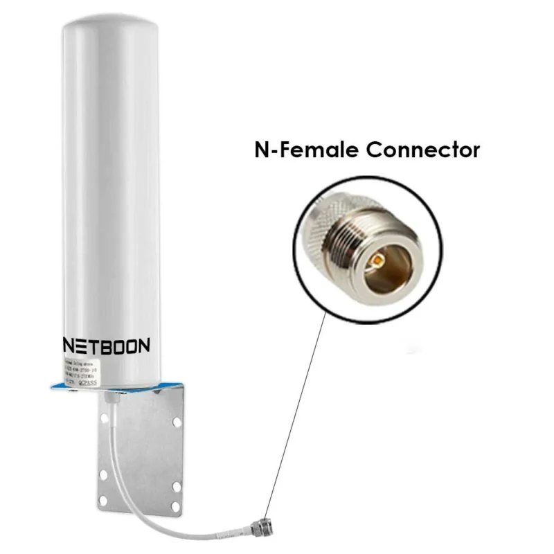
In many RF projects, the connector choice looks simple at first. A cable has an N connector, the equipment has another RF port, and an adapter seems like the only missing piece.
However, the adapter is also part of the transmission path.
A small difference in connector design, impedance, or machining accuracy can affect the final RF result. This is why engineers do not select an n type adapter only by checking whether the two interfaces can be screwed together.
A suitable adapter needs to match the whole connection system:
- Connector interface
- Gender combination
- Frequency range
- Impedance
- Installation environment
For example, an antenna installation may need a rugged N adapter for outdoor use, while a laboratory setup may focus more on VSWR consistency during repeated measurements.
A detailed RF connector guide can help compare different RF interfaces before selecting a specific adapter model.
What Problems Can an N Type Adapter Solve in RF Connections?
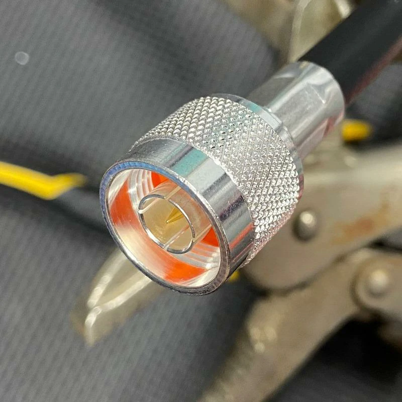
Close-up image of an N male RF connector showing its threaded coupling nut, center pin and internal dielectric structure. N male connectors are commonly used with N female antennas, equipment ports and RF adapters in 50-ohm systems.
A typical situation looks like this:
- An antenna uses an N female interface.
- The testing equipment uses an SMA port.
- The existing cable assembly cannot be replaced immediately.
Instead of changing the complete system, an adapter provides a practical connection method.
For most applications, N adapters are designed around a 50 ohm system, which helps keep the signal path consistent.
The adapter itself does not improve the signal. Its job is to avoid creating a weak point between two RF components.
Which N Adapter Structure Fits Your Installation?
The same N interface can appear in several mechanical designs. Choosing the correct structure depends on where the adapter will be installed.
N Male to Female Adapter
This configuration is commonly used when two devices have different connector genders.
Typical use:
- Equipment port conversion
- Antenna interface matching
- Cable connection adjustment
The male side uses a center pin contact, while the female side provides a socket connection.
N Female to Female Adapter
An n female adapter is often selected when two cables with N male connectors need to be connected together.
N Male to Male Adapter
This structure is less common but useful in specific connection scenarios.
Typical applications:
- Connecting two N female ports
- Equipment interface conversion
- RF module testing
The selection depends on the connector interfaces already available in the system.
Right Angle and Bulkhead N Adapter
Mechanical space is often ignored during early design, but it becomes important after equipment assembly.
A straight adapter may not fit well when:
- The cable needs to exit close to a panel
- The installation space is narrow
- The cable cannot tolerate sharp bending
A right angle design changes the cable direction and helps with routing.
A bulkhead n adapter is used when the connector needs to pass through a panel or enclosure wall.
How Does Connector Accuracy Affect N Adapter Performance?
RF adapters work at the boundary between two components. The contact area is small, but the electrical requirement is high.
Several details can influence performance:
- Center pin alignment
- Contact pressure
- Thread machining accuracy
- Surface plating quality
- Internal dielectric structure
A loose mechanical connection may create unstable contact. In measurement systems, this can appear as inconsistent test results. In communication equipment, it may increase signal reflection.
For systems using coaxial cables, the adapter should also be selected together with the cable specification. Cable type, connector structure, and adapter design work as one RF transmission path.
For example, engineers comparing low-loss connections often review the RG316 coaxial cable guide because cable attenuation and connector transition both affect the final signal performance.
What Should Be Confirmed Before Ordering an N Adapter?
Before placing an order, it is better to define the application first rather than only providing a connector name.
The basic specification normally includes:
- N male or N female interface
- Adapter structure
- 50Ω or other impedance requirement
- Operating frequency
- Mounting method
- Required RF performance
For custom applications, additional information may be needed:
- Cable type
- Installation drawing
- Test frequency
- Environmental requirement
Providing these details reduces the chance of receiving an adapter that fits mechanically but does not meet the RF requirement.
When Should You Use an N Female Adapter?
In real RF projects, the connector interface is often decided long before the final assembly stage.
A common situation is that the equipment has already been selected, the cable has already been prepared, but the connector direction does not match.
For example:
- Two RF cables both use N male connectors.
- An antenna port requires an N male connection.
- A test setup needs an additional extension point.
Changing the whole cable assembly is possible, but it is not always the most practical solution.
This is where an n female adapter becomes useful.
By providing a female-to-female connection, the adapter creates a transition point between existing RF components while keeping the original cable structure unchanged.
How Does an N Female Adapter Work in a Coaxial System?
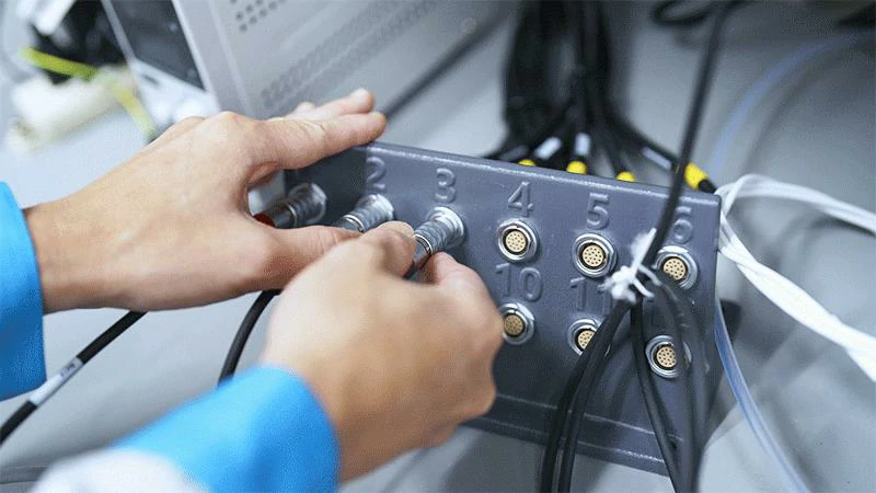
Technician installing RF connectors and cable assemblies on an equipment panel. Correct connector alignment and secure installation help maintain reliable electrical contact in RF communication and testing systems.
An N female adapter uses socket contacts on both sides, allowing two N male connectors to be joined together.
The internal contact design is important because RF signals travel through a very small transition area.
A properly manufactured adapter should maintain:
- Correct center conductor alignment
- Stable outer conductor contact
- Consistent 50Ω impedance
- Reliable mechanical connection
In coaxial applications, the adapter becomes part of the transmission path. Even though it is a small component, its electrical characteristics can influence the complete system.
Supporting RF Laboratory Testing
In laboratories, engineers frequently switch between different test setups.
An N female adapter can help connect:
- Different cable assemblies
- Calibration components
- RF test equipment
However, for precision measurements, every additional connection should be considered.
Additional adapters may influence:
- VSWR results
- Return loss measurement
- Repeatability
How Can N to SMA Adapters Connect Different RF Interfaces?
N and SMA connectors are often found in the same RF system, but they usually appear in different parts of the design.
N connectors are frequently used where mechanical strength and cable connection stability are important.
SMA connectors are more common on compact RF devices and laboratory equipment.
A typical connection may look like this:
Antenna system → N cable → N to SMA adapter → RF module
or:
VNA port → SMA cable → N to SMA adapter → Device under test
The adapter solves the interface difference without changing the original equipment structure.
What Should You Consider When Selecting an N to SMA Adapter?
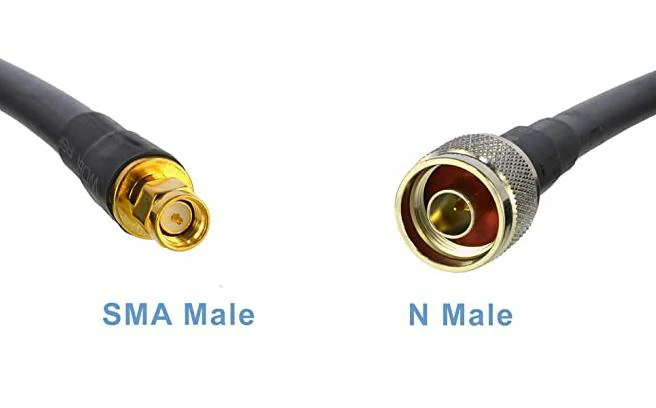
Close-up comparison of SMA male and N male RF connectors installed on a coaxial cable. This connector combination is commonly used to link compact RF equipment with antennas, communication devices and test instruments.
An n to sma adapter should be selected according to the actual working environment.
The main points include:
Connector Direction
Common combinations include:
- N male to SMA female
- N female to SMA male
- N male to SMA male
- N female to SMA female
The correct gender combination depends on the ports already available.
Frequency Capability
Not every adapter with the same connector combination performs the same.
Different designs may use different:
- Contact structures
- Insulation materials
- Machining tolerances
For low-frequency applications, the requirements may focus on durability.
For microwave testing, engineers normally pay more attention to VSWR and insertion loss.
Cable and Equipment Matching
An adapter should not be selected separately from the cable.
For example:
- RG316 cable assemblies may focus on flexibility.
- Semi-rigid cables may focus on phase stability.
- Low-loss cables may focus on attenuation control.
The cable, connector, and adapter together determine the final RF path.
N to SMA Adapter Selection Reference
| Item | N Interface | SMA Interface |
| Common Position | Antenna, communication equipment | RF modules, test ports |
| Mechanical Size | Larger structure | Compact structure |
| Connection Style | Threaded coupling | Threaded coupling |
| Main Advantage | Mechanical durability | Space saving |
| Adapter Purpose | Connect different RF interfaces | Complete system transition |
How Does N to BNC Adapter Help in RF Testing?
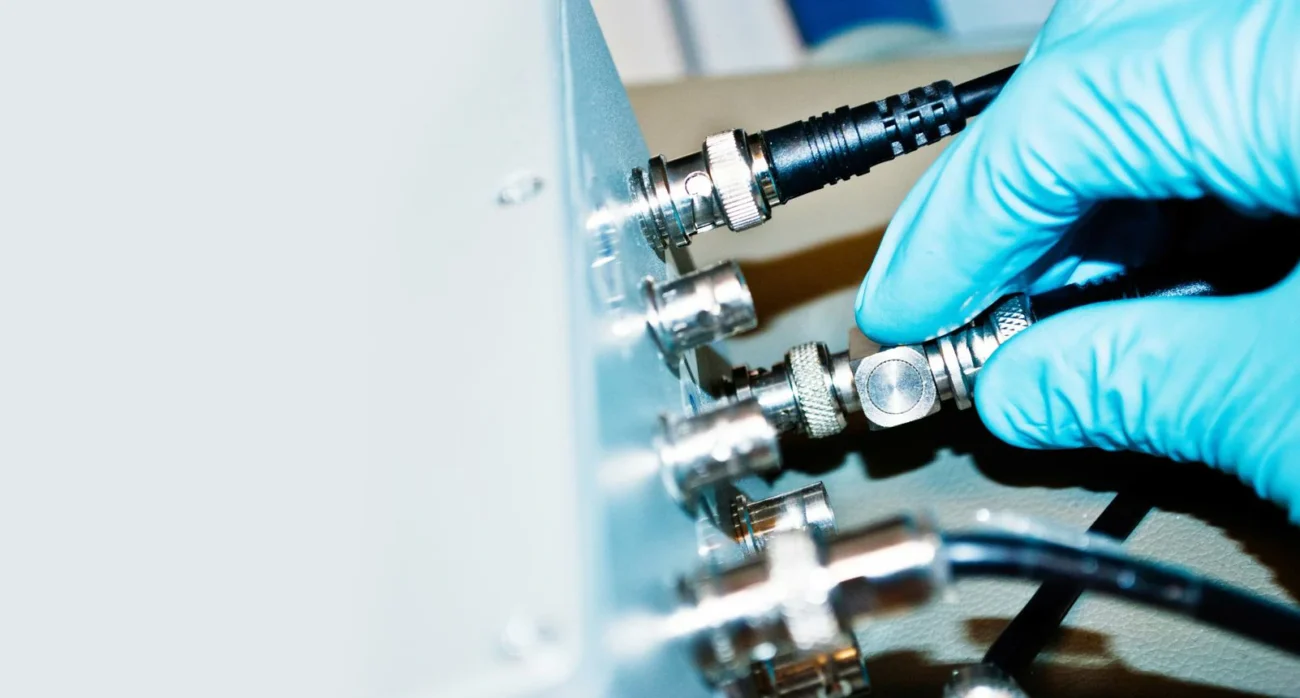
BNC connectors are common in general electronic testing because they allow fast connection and removal.
N connectors are more frequently used in RF systems where a threaded connection is preferred.
An n to bnc adapter provides a bridge between these two environments.
A typical example:
A laboratory instrument uses a BNC output, while the RF device under test uses an N interface.
Instead of replacing the instrument cable, an adapter provides a simple connection method.
Why Does Impedance Matter During N to BNC Conversion?
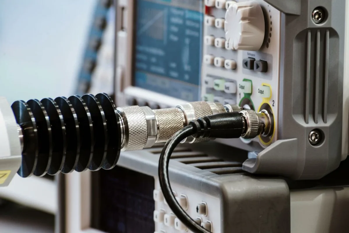
The biggest point to check is not only whether the connectors fit, but whether the electrical characteristics match.
Many RF N systems use 50Ω impedance.
BNC systems may exist in both:
- 50Ω versions
- 75Ω versions
Using the wrong impedance combination may affect measurement results.
Possible effects include:
- Increased reflection
- Higher VSWR
- Measurement deviation
When adapters are used in testing systems, engineers often check the whole signal path rather than only one component.
Related RF measurement concepts such as return loss evaluation and insertion loss testing are also important when analyzing adapter impact.
How Should RF Engineers Evaluate N Adapter Performance?
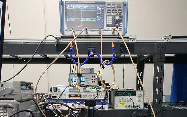
Laboratory RF measurement setup containing a vector network analyzer, coaxial test cables and multiple RF adapters. Engineers use this type of setup to evaluate insertion loss, return loss, VSWR and connector consistency.
An RF adapter is often treated as a small accessory during system design.
In practice, it sits between two important components.
A communication system may already have the antenna selected. The cable route may already be fixed. The test equipment may already be installed.
Then a connection problem appears:
- The equipment port does not match the cable.
- The test cable uses another connector type.
- The original assembly cannot be replaced.
The adapter becomes the connection point that keeps the whole system working.
For an n type adapter, the important question is not only whether two connectors can be connected. The real question is whether the adapter can maintain the expected RF characteristics after installation.
Why Should Impedance Be Checked Before Choosing an N Adapter?
RF signals do not only travel through the outside shape of a connector.
Inside the adapter, the center contact, dielectric material, and housing dimensions all affect the signal path.
Most N connector applications use a 50Ω system.
This is why many projects specify a 50 ohm n adapter instead of only describing the connector type.
What Makes a Coaxial N Adapter Suitable for RF Applications?
Two adapters can look almost identical from the outside.
The difference is usually inside.
Several details affect RF performance:
Contact Structure
The center contact needs accurate positioning.
A small deviation can change the electrical transition, especially at higher frequencies.
Material and Plating
The contact material and surface treatment influence long-term reliability.
This becomes more important in:
- Outdoor antenna systems
- Industrial communication equipment
- Frequent test environments
How Can N Adapters Affect RF Testing Accuracy?
During RF measurement, every connection is part of the test setup.
A common mistake is to focus only on the instrument and ignore the adapters between the instrument and the device under test.
For example:
VNA Port → Test Cable → N Adapter → DUT
The measured result includes the influence of the adapter.
This is why test engineers pay attention to adapter consistency.
How Does VSWR Testing Help Check N Adapter Quality?
VSWR is often used when checking whether a connection introduces reflection.
A poor transition inside the adapter may cause part of the signal to return toward the source.
Possible causes:
- Incorrect connector specification
- Poor contact condition
- Damaged interface
- Manufacturing variation
When evaluating adapter performance, VSWR is normally checked together with other RF parameters.
The VSWR guide for RF testing explains how reflected signals are related to impedance matching and RF transmission quality.
Why Is Return Loss Important for Adapter Evaluation?
Return loss provides another way to view reflected signal behavior.
In production testing, return loss data can help identify differences between samples.
For example:
Two adapters may have the same external dimensions.
Does Adding More RF Adapters Increase Signal Loss?
The answer depends on the application.
In a simple communication connection, adding one adapter may have very little influence.
In a precision measurement path, every additional transition deserves attention.
A longer RF path may include:
Cable + Adapter + Connector + Adapter + Instrument
Each interface introduces another connection point.
For this reason, test setups often try to keep the signal path simple.
The same principle applies to cable selection. Cable construction and attenuation characteristics should be considered together with the adapter. The RG316 coaxial cable guide provides more information about cable characteristics in RF applications.
What Information Should Be Provided When Ordering N Type Adapters?
Many adapter inquiries start with a short description:
“Need N adapter.”
For standard products, this may be enough.
For engineering projects, more information is needed.
A supplier normally needs to confirm:
- N male or N female
- Adapter structure
- Working frequency
- Impedance requirement
- Installation method
- Application environment
For example, a customer building an antenna system and a customer preparing a VNA test fixture may both ask for an N adapter.
The connector name is the same.
The actual requirement is different.
N Adapter Specification Confirmation Sheet
| Item | Customer Confirmation |
| Connector Interface | N / SMA / BNC conversion requirement |
| Gender | Male or Female |
| Structure | Straight / Right Angle / Bulkhead |
| Impedance | 50Ω or other requirement |
| Frequency Range | Working frequency |
| Application | Antenna / Testing / Communication |
| RF Requirement | VSWR / Return Loss / Insertion Loss |
Where Are N Type Adapters Used?
N adapters appear in many RF systems because different equipment manufacturers may select different connector interfaces.
Wireless Communication
Common examples:
- Base station equipment
- Outdoor antennas
- RF distribution systems
The main requirement is usually stable connection under long-term operation.
RF Laboratory
Typical applications:
- VNA testing
- Signal measurement
- Prototype verification
Here, connection repeatability becomes important because the same setup may be tested many times.
Equipment Integration
During product development, changing every cable or connector is not always practical.
An adapter can provide a simple interface transition while keeping the existing design.
The final RF result depends on the whole path:
Connector → Adapter → Cable → Equipment
not only the adapter itself.
FAQ
What does an N type adapter do?
It connects RF components with different N interfaces or converts between N and other connector types.
Is a 50 ohm N adapter common?
Yes. Most RF N adapter applications use 50Ω impedance systems.
Can an N adapter be used with antennas?
Yes. N adapters are widely used in antenna and wireless communication systems.
Do you provide N adapters with cable assemblies?
Yes. Adapter and cable assembly solutions can be matched according to the application requirement.
Can N adapters be used outdoors?
Many N adapters are used in outdoor RF systems. The environment and protection requirement should be confirmed first.
