
The first sample worked. The production batch did not.
This is a situation RF engineers see more often than expected.
A prototype cable assembly may pass a basic signal check because the cable is short, installed in open space, and tested under ideal conditions. After moving into the final equipment, the same cable may experience higher loss, unstable measurements, or unexpected interference.
The difference is usually not the connector interface.
It is the cable structure.
A coaxial cable used in an RF system is a complete transmission path. The conductor material, dielectric spacing, shielding design, cable diameter, and termination method all influence the final result.
For engineers and purchasing teams, selecting a cable based only on connector type is one of the easiest ways to create problems later in production.
A SMA connector does not define an RF cable assembly.
The actual performance depends on the combination of:
- Cable type
- Impedance
- Operating frequency
- Cable length
- Connector matching
- Assembly process
- Testing requirements
This guide focuses on how to evaluate coaxial cables from an engineering and sourcing perspective.
How Does Coaxial Cable Transfer RF Signals Efficiently?
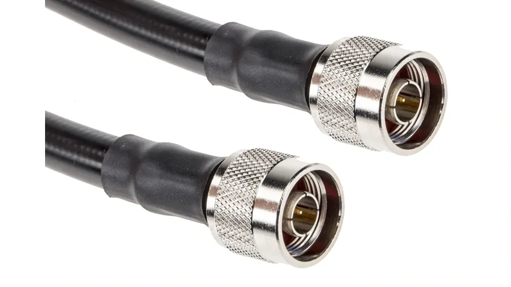
Flexible SMA to SMA RF coaxial cable assembly designed for 50 ohm RF systems, providing reliable signal transmission for wireless communication equipment, antenna applications, and laboratory testing systems.
The structure looks simple, but small changes affect RF behavior.
For example, changing the dielectric material changes the electrical spacing between conductors. Increasing the conductor diameter may reduce conductor loss, but it also changes cable flexibility and installation requirements.
The four basic layers are:
| Cable Layer | Main Function | Engineering Consideration |
| Center conductor | Carries RF energy | Material and diameter affect resistance loss |
| Dielectric | Maintains conductor spacing | Controls impedance stability |
| Shield | Provides isolation | Affects EMI protection and signal integrity |
| Jacket | Protects cable structure | Influences durability and environment suitability |
A buyer comparing two coaxial cables should not only ask:
“Which cable has lower loss?”
The better question is:
“Does this cable fit the complete RF path?”
A low-loss cable with an unsuitable connector termination can still create a poor assembly.
Where Are Coaxial Cables Used in RF Systems?

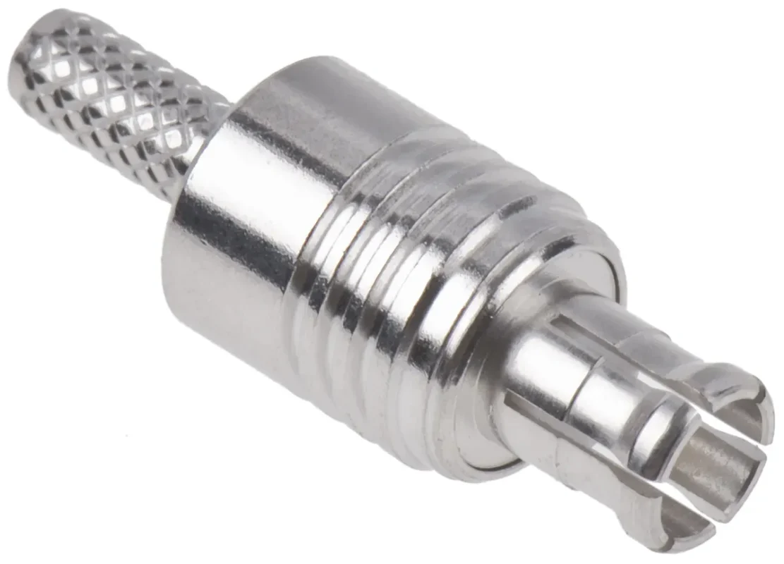
Detailed view of an RF coaxial connector showing the contact structure and mechanical design used for reliable cable termination and high frequency signal transmission.
The same coax cable model can behave differently depending on where it is installed.
Inside a wireless device, space is usually limited. Engineers often need a flexible cable with a small bending radius.
In an antenna system, cable loss becomes more important because the transmission distance is longer.
In a test environment, repeatability becomes a priority. A cable that works for general communication may not be suitable as a measurement cable.
Common applications include:
- Wireless communication equipment
- GPS and navigation systems
- Antenna connections
- RF laboratory testing
- Industrial communication devices
- Microwave measurement systems
A typical selection difference:
| Application | Main Concern | Common Cable Requirement |
| Internal RF module | Space and routing | Flexible coaxial cable |
| Antenna feeder | Transmission loss | Low loss coax cable |
| RF test equipment | Repeatability | Stable phase and low VSWR |
| Outdoor communication | Environment | Weather-resistant construction |
A frequent mistake during purchasing is replacing an existing cable with a visually similar model.
The connector may fit.
The electrical performance may not.
Why Does Cable Structure Matter More Than Connector Appearance?
Many RF sourcing problems start from a simple assumption:
“If the connector is the same, the cable should be interchangeable.”
That assumption is risky.
A coaxial cable assembly is determined by the relationship between the cable and connector.
Take an SMA cable assembly as an example.
An SMA connector designed for RG316 is normally different from an SMA connector designed for RG58 or RG142.
The differences may include:
- Rear body size
- Ferrule diameter
- Center pin design
- Crimp area
- Dielectric support structure
If the connector is forced onto the wrong cable diameter, the assembly may pass a continuity test but fail RF testing.
This is why experienced suppliers usually confirm cable specifications before quoting a replacement.
Important information includes:
- Cable model
- Cable outer diameter
- Required frequency range
- Length tolerance
- Connector type
- Termination method
A complete RF request should describe the assembly, not only the connector.
What Makes 50Ω and 75Ω Coaxial Cables Different?
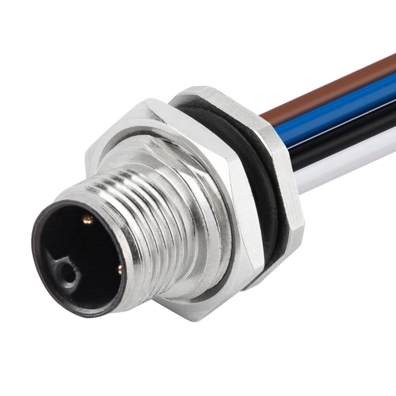
Panel mount circular connector with cable assembly designed for reliable electrical connection in industrial equipment, control systems, and electronic applications.
Two coaxial cables may look almost identical but have different impedance values.
Most RF communication systems use 50Ω coaxial cables.
The reason is related to power handling and transmission efficiency in RF systems.
It is a system-level requirement.
| Application | Recommended Impedance | Common Use |
| RF communication | 50Ω | Wireless equipment |
| Antenna connection | 50Ω | RF signal transmission |
| Laboratory testing | 50Ω | Measurement systems |
| Video transmission | 75Ω | CCTV and broadcast |
| Broadband network | 75Ω | CATV |
Using the wrong impedance may introduce reflections. In practical RF testing, this can appear as increased VSWR or unstable measurement results.
Avoid Selecting Coaxial Cable Only by Interface Type
A purchase request such as:
“SMA male to SMA male cable”
is incomplete.
These details directly affect the manufacturing process.
For example, a 2-meter antenna cable and a 20-centimeter internal jumper may both use SMA connectors, but the recommended cable construction can be completely different.
The connector is only the connection point.
The cable determines how the RF signal travels between those points.
How Does Cable Construction Affect Coaxial Cable Selection?
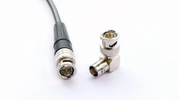
BNC coaxial connector adapter assembly designed for quick RF connections in test instruments, communication systems, and signal transmission applications.
A cable can have the correct impedance and still be the wrong choice for the installation.
This usually happens when the mechanical requirements are ignored.
RF engineers often focus on electrical specifications first:
- Frequency range
- Attenuation
- VSWR
- Impedance
Those numbers matter, but the cable also has to survive the physical environment.
A cable routed inside a compact enclosure may need repeated bending. A cable installed near motors or switching power supplies may require better shielding. A cable used in outdoor antenna equipment may need stronger protection against moisture and temperature changes.
The construction determines where the cable can realistically be used.
How Does Shielding Influence RF Signal Quality?
The shield layer is not only a protective metal cover.
It directly affects how much external interference enters the RF path and how much signal leaks out.
In practical applications, poor shielding can create problems such as:
- Increased noise level
- Unstable measurement results
- Reduced signal consistency
- Interference from nearby circuits
A cable used inside a laboratory setup may operate in a relatively clean environment.
The same cable installed beside:
- Power converters
- Motor controllers
- Digital processing boards
may produce very different results.
Different coaxial cables use different shielding structures:
| Shield Structure | Characteristics | Typical Application |
| Single braid | Flexible, economical | General RF connection |
| Double shielding | Better isolation | Communication equipment |
| Foil + braid | Improved high-frequency shielding | Noise-sensitive systems |
| Semi-rigid metal shield | Excellent stability | Microwave applications |
However, better shielding does not automatically mean better for every application.
A heavily shielded cable may become:
- Less flexible
- Larger in diameter
- More difficult to terminate
For a short internal jumper, flexibility may be more valuable than maximum shielding.
For an antenna feeder, the priority may be completely different.
Should You Choose Flexible, Semi-Rigid, or Low Loss Coaxial Cable?
There is no universal “best” coaxial cable.
The correct choice depends on the RF path.
Flexible coaxial cable is commonly selected when installation space is limited.
Typical examples:
- Wireless modules
- GPS devices
- IoT equipment
- Internal equipment wiring
The advantage is simple:
The cable can be routed around obstacles without excessive mechanical stress.
Applications include:
- Microwave modules
- Precision RF assemblies
- Internal high-frequency equipment
The metal outer conductor provides excellent shielding and predictable performance.
The trade-off is installation flexibility.
Semi-rigid cable is not suitable when the assembly needs frequent movement.
Low loss coaxial cable is usually considered when transmission distance increases.
A few centimeters of additional loss may not matter in a short jumper.
In a several-meter antenna connection, the same loss can directly affect system performance.
A practical comparison:
| Cable Category | Main Advantage | Typical Application |
| Flexible coax | Easy routing | Internal RF connection |
| Semi-rigid coax | Stable RF characteristics | Microwave equipment |
| Low loss coax | Reduced attenuation | Antenna feeder systems |
| Small diameter coax | Space saving | Compact electronics |
The selection process should start from the installation condition, not from the cable name.
How Do Frequency and Cable Length Affect Coaxial Cable Loss?
Many cable selection mistakes happen because the operating frequency is underestimated.
A cable that performs well at 900 MHz may behave differently at 5.8 GHz.
As frequency increases, attenuation normally increases.
Cable length also directly affects total loss.
The cable is only one part of the signal path.
A common example:
A system uses:
- 2 m coaxial cable
- Two RF connectors
- One adapter
The cable loss may look acceptable by itself, but the additional connection points increase the final insertion loss.
Information Asset: Coaxial Cable Loss Evaluation Sheet
Before selecting a cable, engineers can estimate the RF loss using the following information:
| Parameter | Required Information |
| Cable Type | RG316 / RG174 / Low Loss Cable / Microwave Cable |
| Operating Frequency | MHz or GHz |
| Cable Length | Meter |
| Attenuation | dB/m at target frequency |
| Connector Quantity | Number of RF interfaces |
| Adapter Quantity | Number of transitions |
| Final Loss Target | Maximum acceptable dB |
Selecting a cable only from the connector type while ignoring the RF budget.
Why Does Cable Diameter Matter During Installation?
Cable diameter affects more than appearance.
Before replacing a cable, check:
- Available routing space
- Required bending angle
- Connector rear dimensions
- Strain relief requirements
A cable that works on the test bench may fail after installation because the bending radius is too small.
Mechanical stress can change the cable geometry and affect RF performance.
How Do Different Coaxial Cable Types Match Different Applications?
The cable model should follow the system requirement.
A few common examples:
RG316
RG316 is widely used where flexibility and small diameter are important.
Typical applications:
- Internal RF wiring
- Compact devices
- Short antenna connections
It is not usually selected for long-distance transmission because attenuation becomes significant.
Microwave Cable
Microwave cables are typically used where frequency stability and measurement repeatability are required.
Applications include:
- RF test systems
- Microwave instruments
- Precision measurement setups
These cables often prioritize electrical stability over flexibility.
Cable Application Selection Reference
| Cable Type | Main Consideration | Suitable Application |
| RG316 | Flexible and compact | Internal RF wiring |
| RG174 | Small diameter | Short RF connections |
| RG58 | General-purpose RF | Laboratory and communication equipment |
| Low loss coax | Reduced attenuation | Antenna systems |
| Microwave cable | High-frequency stability | RF measurement |
The correct cable is usually a compromise between electrical performance, installation limits, and production cost.
A procurement request that only specifies “50Ω RF cable” is normally not enough for accurate selection.
How Do Cable Assemblies Change the Way Coaxial Cables Are Used?
A coaxial cable specification is incomplete until the termination method is decided.
This is something that often appears during sample confirmation.
A customer may provide only:
“SMA cable, 1 meter.”
From a production perspective, several questions remain unanswered.
Which SMA?
For which cable?
Straight or right-angle?
Crimp or solder?
What frequency range?
Will the cable be used for antenna transmission or laboratory testing?
The cable itself is only half of the assembly.
The finished RF path is created by the combination of:
- Coaxial cable
- Connector interface
- Termination process
- Mechanical protection
- Inspection method
A cable assembly supplier is not only making a cable with two plugs installed. The supplier is controlling how the complete RF path is built.
Why Does Connector Matching Matter in Coaxial Cable Assemblies?
The front interface is usually the easiest part to identify.
The hidden part is the rear structure.
Different coaxial cables have different:
- Outer diameter
- Dielectric thickness
- Center conductor size
- Shield structure
The connector must be designed around those dimensions.
A common example is SMA.
An SMA connector for RG316 is not normally interchangeable with an SMA connector for RG58.
Although both use the same mating interface, the cable-side structure can be different.
If the connector and cable are not matched correctly, problems may appear during:
- Crimping
- Soldering
- Pull testing
- RF measurement
The finished assembly may look acceptable, but the electrical performance can change.
A practical BOM description should include more than:
“SMA cable.”
A clearer description would include:
| Item | Example Requirement |
| Connector | SMA male |
| Cable | RG316 coaxial cable |
| Impedance | 50Ω |
| Length | 300 mm |
| Frequency | DC–6 GHz |
| Termination | Crimp type |
| Inspection | VSWR check if required |
This information gives production a clear target.
When Is a Finished RF Cable Assembly Better Than Buying Raw Cable?
Raw cable is useful when the customer already has internal assembly capability.
For many equipment manufacturers, however, a finished assembly reduces unnecessary variables.
The reason is not only convenience.
Cable termination quality affects repeatability.
Small differences during manual assembly can change:
- Contact resistance
- Shield connection
- Mechanical strength
- RF consistency
Typical problems found during production include:
- Incorrect stripping length
- Damaged dielectric during stripping
- Poor braid contact
- Excessive solder heating
- Loose connector attachment
These problems are difficult to identify by appearance alone.
A professional cable assembly process usually includes:
- Incoming material control
- Connector and cable matching
- Assembly process control
- Electrical inspection
- Final labeling
For low-volume prototypes, customers may accept manual adjustment.
For repeated production, consistency becomes much more important.
What Tests Should Be Included Before Shipping Coaxial Cable Assemblies?
A cable assembly can look perfect and still fail in an RF system.
This is where the difference between electrical inspection and RF inspection becomes important.
A continuity tester can confirm the circuit path.
It cannot tell whether the RF energy is transferring correctly.
Basic Production Inspection
Most cable assemblies should include basic checks:
Continuity
Confirm:
- Center conductor connection
- Shield connection
Short circuit inspection
Confirm:
- No unwanted contact between signal and shield
Mechanical inspection
Check:
- Connector appearance
- Cable damage
- Crimp condition
- Label information
These checks are suitable for general production control.
RF Performance Testing
For higher-frequency or sensitive applications, additional testing may be required.
Common measurements include:
VSWR
VSWR reflects how much RF energy is returned because of impedance mismatch.
Possible causes include:
- Incorrect connector installation
- Damaged cable section
- Poor termination
- Wrong cable selection
Insertion Loss
Insertion loss shows how much signal is lost through the assembly.
The result changes with:
- Cable length
- Frequency
- Cable material
- Connector quantity
A 100 mm jumper and a 5 m antenna cable should not be judged by the same loss expectation.
Return Loss
Return loss is often checked in applications where signal reflection needs closer control.
Examples:
- RF testing equipment
- Communication systems
- Microwave applications
Information Asset: RF Cable Assembly Pre-Shipment Checklist
A practical inspection sheet:
| Check Item | Confirm Before Shipment |
| Cable model | Match drawing or specification |
| Connector interface | Correct gender and series |
| Impedance | 50Ω / 75Ω confirmed |
| Cable length | Within tolerance |
| Assembly appearance | No damage |
| Continuity | Pass |
| Pull strength | Required for application |
| VSWR | Tested when specified |
| Loss data | Provided when required |
Not every project requires a full RF report.
The inspection level should match the application risk.
How Should Buyers Evaluate a Coaxial Cable Supplier?
Price comparison is common during sourcing, but RF cable assemblies are not always directly comparable.
Two suppliers may quote the same description:
“SMA to SMA cable.”
The actual products may differ in:
- Cable model
- Connector material
- Plating
- Assembly method
- Testing standard
Before comparing prices, confirm the specifications are identical.
What Information Should Be Provided During RF Cable Inquiry?
A supplier can recommend the correct assembly faster when the request includes complete information.
FAQ
Can I replace my existing coaxial cable with another cable using the same connector?
Not directly.
The connector interface only confirms mechanical mating.
Why does a coaxial cable work at low frequency but fail at higher frequency?
Higher frequencies are more sensitive to cable loss, impedance changes, connector quality, and assembly accuracy.
A cable that performs well at 900 MHz may require additional evaluation at several GHz.
Does a low-loss coaxial cable always provide better results?
Not always.
Low-loss cable is useful for longer RF paths, but it may be larger, less flexible, and more difficult to install.
The best choice depends on the complete system requirement.
Why should cable length be confirmed before production?
A cable that is too short may create installation problems. A cable that is unnecessarily long increases RF loss.
What is the difference between coaxial cable and coaxial cable assembly?
Coaxial cable refers to the cable itself.
A coaxial cable assembly includes the cable plus installed connectors, termination process, and inspection requirements.
What should I prepare before asking for an RF cable quotation?
At minimum provide:
- Connector type
- Cable type
- Length
- Frequency
- Impedance
- Application
- Quantity
More complete specifications reduce the risk of selecting a cable that only looks correct but does not fit the RF requirement.
