
A connector can fit onto a coaxial cable, survive a pull test, and still be unsuitable for the finished RF assembly.
Consider a purchasing team ordering SMA plugs for RG316 cable. During production, however, the crimp ferrule does not grip the braid consistently. Some assemblies pass continuity testing but show unstable return loss after bending.
The problem may not be the SMA mating interface. It may be the connector’s rear geometry, center contact, or termination dimensions.
Selecting coaxial cable connectors should therefore begin with the cable itself, not simply the connector family shown in a catalog.
For engineers and procurement teams, the practical task is to confirm cable dimensions, impedance, conductor construction, and shield compatibility before approving a connector part number.
Which Cable Dimensions Must Be Verified Before Selecting a Connector?
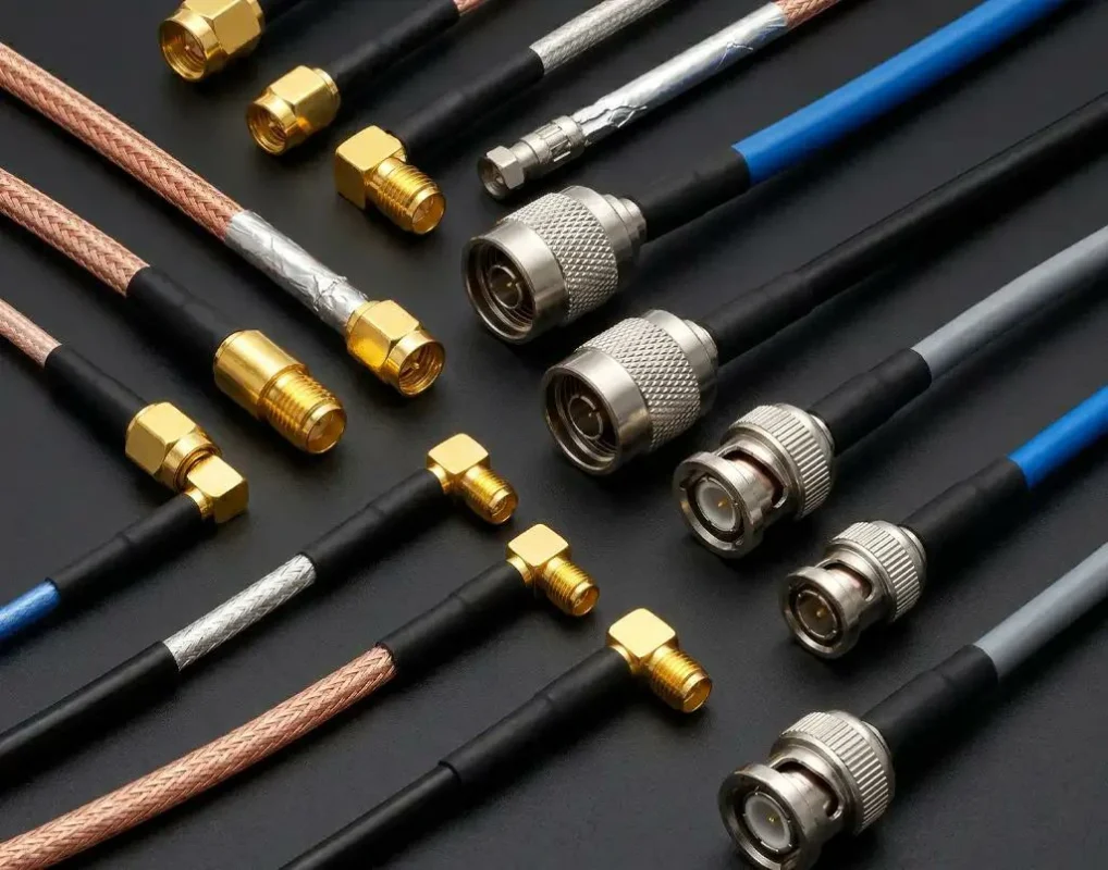
A cable designation is a useful starting point, but it is not a complete connector specification.
Two cables sold under the same general family name may differ in jacket material, shielding construction, or conductor dimensions. These differences become significant when the connector uses a closely fitted rear body, crimp sleeve, or solder contact.
Start With the Exact Cable Part Number
RG58, RG174, RG316, and LMR400 are familiar cable designations. They help narrow the selection, but the exact manufacturer and part number should still be confirmed.
For example, a connector advertised for RG58 may be designed around a particular jacket diameter and braid construction. Another RG58 variant may require a different ferrule or assembly procedure.
The same concern applies to flexible, low-loss, and double-shielded cable variants.
A purchasing specification stating only “SMA male connector for RG58” leaves too much room for interpretation. The supplier needs to know which RG58 cable will actually be terminated.
If the original cable datasheet is available, use it as the dimensional reference. Otherwise, measure a representative cable sample and verify the dimensions against the connector manufacturer’s drawing.
The TEJTE RG Cable Guide provides additional background on RG cable families, while the connector selection should be based on the specific cable construction.
Measure Jacket and Dielectric Diameters Separately
Cable outside diameter is often the first dimension checked. It should not be the only one.
A coaxial cable has several concentric layers, and each interacts with a different part of the connector.
Identify Solid and Stranded Center Conductors
The center conductor determines how the signal path connects to the connector’s center contact.
A stranded conductor may require a different contact bore, crimp geometry, or soldering procedure.
A poorly matched contact can create several problems: incomplete insertion, loose strands, inconsistent crimp deformation, or excessive solder buildup.
Some defects are visible during assembly. Others become apparent only after cable movement, vibration, or repeated handling.
The safest approach is to confirm both the conductor diameter and construction against the connector manufacturer’s termination specification.
Record the Shield Construction Before Choosing a Ferrule
The shield is part of the RF transmission path, not merely a protective layer.
Common constructions include single braided shields, double braided shields, and foil-plus-braid arrangements. Their thickness and handling requirements can differ substantially.
A ferrule intended for one shield configuration may not compress another configuration correctly.
If the ferrule is too large, the braid may not be retained securely. If it is too small, excessive compression can damage the shield, jacket, or underlying dielectric.
Ferrule selection must account for the actual shield construction and the approved crimp dimensions. Suggested source: original assembly photography or licensed industrial image.
For production orders, the approved ferrule, crimp die, and cable preparation dimensions should be recorded together. Substituting only one of these components can change the termination result.
How Do You Match Connector Rear Geometry to RG and LMR Cables?
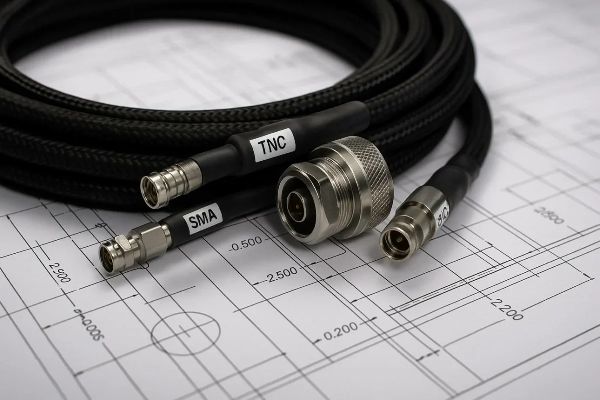
The front of an RF connector determines which equipment interface it mates with. The rear determines which cable it can terminate.
That distinction is frequently overlooked during sourcing.
An SMA connector designed for RG316 is not automatically interchangeable with an SMA connector intended for RG58. Both may have identical front mating interfaces, yet their cable entries, center contacts, and ferrules can be entirely different.
Compare Small Coax Families Without Assuming Universal Fit
RG174, RG178, and RG316 are commonly used where cable routing space is limited.
Small coaxial cables may appear similar but require different connector rear geometries and termination details. Suggested source: original cable comparison photograph.
An RG316-compatible connector should not be selected for RG178 simply because both cables are small.
The center contact may not accept the conductor correctly, and the ferrule may be unsuitable for the jacket and braid dimensions.
This is especially relevant when purchasing teams consolidate several cable assembly models under one connector supplier.
Evaluate RG58, RG59, and RG6 With Impedance in Mind
Cable dimensions are only part of the selection.
RG58 is typically a 50-ohm cable, while common RG59 and RG6 constructions are 75-ohm cables. Their applications and connector requirements may therefore differ even when similar connector interfaces are available.
A 75-ohm cable should generally be terminated with a compatible 75-ohm connector for a controlled-impedance system. Substituting a 50-ohm connector merely because it fits mechanically can introduce an impedance discontinuity.
This matters in video distribution, instrumentation, and RF systems where return loss requirements are specified.
Similar-looking connector interfaces may have different impedance specifications. Suggested source: licensed manufacturer technical photography.
The connector’s cable entry must also match the actual RG59 or RG6 construction. Neither designation guarantees universal compatibility across manufacturers.
For procurement, the correct combination is the exact cable part number, connector part number, impedance rating, and approved termination method—not merely a familiar RG designation.
Check Larger Cable Entries for RG213 and LMR400
Larger coaxial cables create a different set of mechanical problems.
RG213 and LMR400-class cables need more space at the connector rear body, but cable outside diameter is still only one part of the fit. The connector must also accommodate the dielectric, center conductor, shield stack, and the termination method specified for that cable.
This matters because larger cable does not tolerate poor rear-body support well. A connector that grips only the jacket may appear secure during assembly, yet cable movement can transfer stress directly to the center contact or shield termination.
For RG213, confirm whether the connector uses a clamp, crimp, solder, or combination termination. The preparation dimensions may vary considerably between connector designs.
LMR400-style cable requires similar care. Its low-loss construction and relatively large diameter mean the center conductor and shield geometry must match the connector design closely. A connector marketed loosely as “for 10 mm cable” is not enough information for production approval.
For repeat production, the connector drawing should identify the supported cable construction rather than relying only on a nominal cable diameter.
Verify Manufacturer-Specific Cable Variants
Cable family names are convenient for purchasing. They are less useful for final engineering approval.
Two cables carrying the same general designation can differ slightly in conductor diameter, braid coverage, jacket thickness, or dielectric dimensions. Those differences may be small on paper but large enough to change how a ferrule crimps or how the center contact fits.
This is a common source of substitution risk.
A buyer may approve one connector against a particular RG316 cable, then later purchase another supplier’s RG316 because the family name appears identical on the BOM. The new cable may still meet its own specification, yet the existing termination process may no longer produce the same result.
The safer production rule is simple: freeze the approved cable part number together with the connector part number and tooling combination.
If a cable supplier changes, treat the change as a compatibility check rather than an automatic substitution.
Which RF Interface Should Be Selected After Cable Fit Is Confirmed?
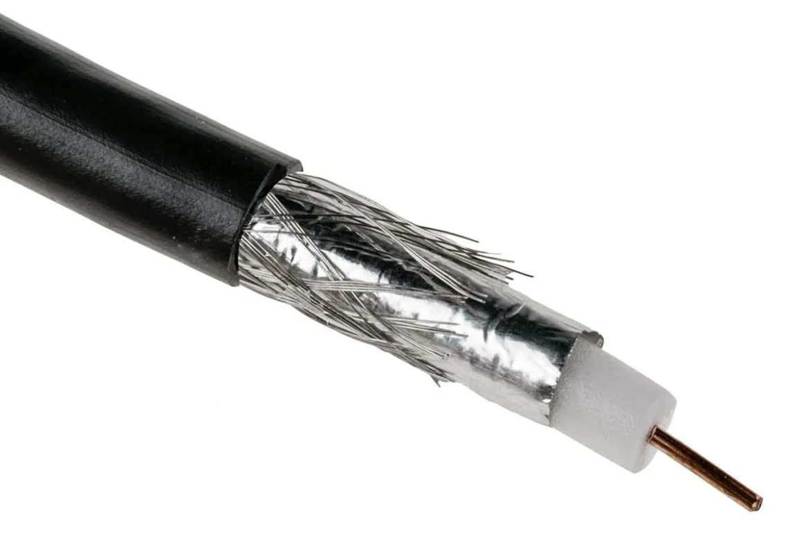
Cable fit solves only the rear half of the connector.
The front interface still has to mate correctly with the equipment, antenna, enclosure, or test port. This is where connector family, gender, polarity, impedance, and mechanical coupling become relevant.
Match SMA and SMB to Compatible Compact RF Connections
SMA is common in compact RF assemblies because it provides a threaded connection in a relatively small package. SMB uses a snap-on interface and can be useful where faster mating is preferred.
The important distinction here is not which family is “better.” It is whether the equipment port and the cable termination requirements point to the same connector configuration.
An SMA male plug for RG58 and an SMA male plug for RG316 may mate with the same SMA female port, but their rear bodies are not interchangeable.
The same principle applies to SMB cable connectors.
Match BNC and TNC to the Required Equipment Interface
BNC and TNC are often selected for equipment that requires frequent connection or more robust field handling.
BNC uses a bayonet coupling, which makes connection fast. TNC uses a threaded coupling, which provides more positive mechanical retention.
That mechanical difference affects serviceability, vibration resistance, and installation time.
Do not select between them only by habit. Start with the actual equipment port, then confirm impedance and frequency requirements.
A 50-ohm BNC and a 75-ohm BNC may look similar to an inexperienced buyer. Mechanical mating alone is not a substitute for correct impedance selection.
Evaluate N-Type for Larger Coax and Field Connections
N-Type connectors are commonly paired with larger coaxial cables, outdoor RF equipment, antenna feeds, and base-station style connections.
Their larger body gives more room for cable entry and mechanical support, but that does not mean any N-Type connector will fit any large coax cable.
A connector intended for RG58 is different from one intended for RG213 or LMR400.
For outdoor assemblies, additional requirements may include sealing, panel mounting, strain relief, and environmental protection. Those features should be specified separately from the basic connector interface.
Keep PL259 and SO239 Applications Within Their RF Limits
PL259 and SO239-style interfaces remain common in radio and general communication equipment.
Their familiarity sometimes leads buyers to treat them as universal RF connectors. That is risky.
Performance depends on the exact connector construction, cable, frequency, and finished assembly. A part that works adequately in a lower-frequency radio application should not automatically be assumed suitable for a higher-frequency RF path.
If the application has a defined return-loss or insertion-loss target, test the finished cable assembly rather than relying on the traditional interface name.
Confirm Gender, Polarity, and Impedance Before Finalizing the Part
A cable-compatible rear body does not help if the front interface is wrong.
Before releasing a connector for production, confirm:
- mating interface
- male or female gender
- standard or reverse polarity where applicable
- 50-ohm or 75-ohm impedance
- cable part number
- mounting style
- operating frequency
That information belongs in the BOM or approved drawing, not only in email history.
How Should Crimp, Solder, and Clamp Termination Be Chosen?
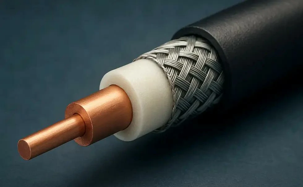
Close-up of a coaxial cable showing its copper center conductor, dielectric insulation, braided shield, and outer jacket. These structural dimensions and materials affect coaxial cable connector compatibility, ferrule selection, and termination quality.
Termination method should follow the connector design, not operator preference.
A crimp connector should be assembled with the approved ferrule, center-contact method, stripping dimensions, and die size. A solder connector requires controlled heat and proper conductor preparation. Clamp designs need the correct cable geometry so the mechanical stack compresses as intended.
Select Crimp Termination From the Approved Connector–Cable Pair
Crimping is attractive in production because it can be fast and repeatable. It is only repeatable when the tooling matches the connector.
A die that is slightly too large may leave the ferrule mechanically loose. One that is too small can distort the ferrule, damage the braid, or compress the dielectric.
Do not approve the process based only on appearance.
Use Solder Termination Where the Connector Design Requires It
Soldering provides a secure electrical joint when the connector is designed for it, but excess heat can create another problem.
PTFE-based dielectrics tolerate heat better than some materials, yet careless soldering can still shift internal parts, leave excessive solder, or alter center-contact positioning.
The operator should use only enough heat to form the joint without turning the connector into a thermal experiment.
Evaluate Clamp Termination for Supported Cable Constructions
Clamp-style connectors can be useful for larger coaxial cables and serviceable installations.
Their advantage is mechanical retention without relying entirely on a crimp ferrule. Their limitation is that the cable preparation and internal stack dimensions must still match the connector precisely.
A clamp connector is not a universal workaround for an uncertain cable size.
Avoid Substituting Tools or Ferrules Without Validation
Production problems often begin with a substitution that appears harmless.
A different ferrule is available. A similar crimp die is already on the bench. The assembly looks acceptable, so production continues.
That is exactly the point where repeatability is lost.
Connector, cable, ferrule, strip dimensions, and tooling should be treated as one approved termination system. If one element changes, verify the assembly again mechanically and, where the application requires it, with RF testing.
How Can You Detect a Connector That Fits Physically but Fails Electrically?
A connector can look perfectly assembled and still create an RF problem.
Continuity testing proves that the center conductor is connected and that no obvious short exists between center and shield. It does not confirm impedance continuity, insertion loss, or return loss across the operating band.
Check for Center-Conductor and Contact Mismatch
The center conductor must fit the connector contact as intended.
If the conductor is too small for the contact, the joint may become mechanically unstable. If it is too large, insertion or crimping can distort the contact. With stranded conductors, loose strands or excessive solder can also change the finished geometry.
The assembly may pass a basic resistance check while producing unstable RF behavior after bending or vibration.
Inspect Shield Continuity and Dielectric Damage
The braid should make consistent contact with the connector body without loose strands entering the dielectric area.
Also inspect the exposed dielectric for crushing, cuts, or heat damage. Small assembly defects near the connector transition can become more significant as operating frequency increases.
Verify VSWR and Insertion Loss at the Intended Frequency
Mechanical retention and RF matching are separate acceptance items.
For assemblies with defined RF requirements, sweep the finished cable with a VNA or appropriate RF test equipment across the required band. Check the specified parameters, typically VSWR or return loss and insertion loss.
Testing only at a low frequency can miss problems that appear near the application’s upper band.
When Is an Adapter Better Than Re-Terminating the Cable?
Re-terminating a qualified cable assembly is not always the lower-risk option.
If the cable length, existing connector, and RF performance are already approved, a suitable coaxial cable adapter may be preferable when only the equipment interface changes.
Re-termination introduces a new stripping operation, center-contact termination, shield connection, and inspection step.
Use an adapter when the existing assembly should remain intact. Re-terminate when the cable is designed for the process and a validated connector and tooling combination is available.
Rigid adapters work well when ports align mechanically. Where the connection would place side load on the equipment port, a short flexible transition cable can reduce stress.
Every added interface also becomes part of the RF path. Adapter loss, mismatch, and connector count should therefore be included in the assembly acceptance criteria.
How Should the Finished Connector Termination Be Inspected?
Production inspection should cover more than appearance.
For RF-qualified assemblies, complete the inspection with the required frequency sweep.
A practical acceptance record can look like this:
| Inspection item | What to verify | Possible mismatch |
| Center contact | Correct position and secure termination | Loose retention or difficult insertion |
| Cable strip | Matches approved preparation dimensions | Compression or incorrect positioning |
| Shield | Full, clean contact with connector body | Poor contact or assembly damage |
| Ferrule / clamp | Correct deformation and retention | Weak braid retention or excessive compression |
| Continuity | Center and shield paths intact | |
| Isolation | No unintended center-to-shield short | |
| RF test | Meets VSWR, return-loss, or insertion-loss target |
Once the process is approved, record the connector part number, cable part number, tooling, strip dimensions, and RF test method together.
That record matters when the same assembly is reordered six months later.
How Can You Verify Cable-to-Connector Compatibility Before Production?
A useful compatibility check treats the connector and cable as one assembly rather than two catalog items.
Coax Cable-to-Connector Fit Matrix
| Cable family | Typical impedance | Rear-body check | Shield termination | Approval |
| RG174 | 50Ω | Small-coax entry | Approved ferrule | Verify PN |
| RG178 | 50Ω | Miniature entry | Cable-specific | Verify PN |
| RG316 | 50Ω | RG316 geometry | Ferrule / braid fit | Verify PN |
| RG58 | 50Ω | RG58 rear body | Crimp / clamp / solder | Verify PN |
| RG59 | 75Ω | RG59 geometry | 75Ω cable termination | Verify PN |
| RG6 | 75Ω | RG6 rear body | Compression / crimp | Verify PN |
| RG213 | 50Ω | Large coax entry | Cable-specific | Verify PN |
| LMR240 | 50Ω | LMR240 geometry | Shield-stack fit | Verify PN |
| LMR400 | 50Ω | LMR400 geometry | Ferrule / clamp fit | Verify PN |
This table is a verification framework, not a declaration that every connector carrying one cable name is interchangeable.
FAQ
Can one connector fit both RG58 and RG316?
Usually not. Even if the front interface is identical, RG58 and RG316 have different cable dimensions. The rear body, ferrule, and center contact must match the actual cable.
Does continuity testing prove a coax assembly is good?
No. Continuity detects open circuits and obvious shorts.
Can a 50-ohm connector be used on 75-ohm coax?
Mechanical mating may sometimes be possible, but the impedance discontinuity can affect RF performance. Use the correct impedance where the system requires controlled matching.
Is a coaxial cable adapter better than replacing the connector?
It can be when the original cable termination is already qualified. The trade-off is an additional interface, which adds some mismatch and loss.
Should connector compatibility be approved only by cable diameter?
No. Cable OD, dielectric diameter, center conductor, shield construction, impedance, and termination method all need to be considered.