
A coaxial cable can pass a continuity test and still be damaged during installation.
The center conductor remains connected. The shield also appears intact. Yet after the cable is pulled through conduit, secured against a panel, and connected to the antenna, insertion loss rises or return loss becomes unstable. The problem may be a crushed dielectric, a kink hidden above the ceiling, a connector carrying cable weight, or excessive pulling force applied during one difficult bend.
A reliable coax cable installation starts before the cable reaches the jobsite. The route, connector size, pulling method, service length, support points, environmental exposure, and final RF acceptance limits should already be defined.
This guide covers the complete field workflow: plan the RF path, measure the installed length, check conduit clearance, control pulling tension, protect connectors, secure the route, and verify the finished assembly.
Define the Installed RF Path Before Ordering Cable
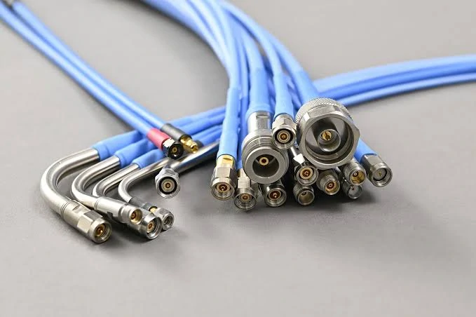
A collection of coaxial cable assemblies featuring various RF connector interfaces. Proper connector selection and cable routing are essential steps in coax cable installation to maintain signal integrity and minimize insertion loss.
Do not begin with cable length alone. Begin with the complete RF path.
A typical route may include a radio, cable assembly, panel bulkhead, surge protector, adapter, and antenna. Every transition adds another mechanical interface and another possible source of mismatch or insertion loss.
Record the following before ordering:
- Source and destination ports
- Connector series, gender, and polarity
- Nominal impedance
- Frequency range
- Maximum RF power
- Cable family
- Adapter and bulkhead quantity
- Indoor and outdoor route sections
- Grounding or bonding locations
- Required final tests
Mechanical compatibility does not confirm electrical compatibility. A 50-ohm and a 75-ohm connector may sometimes appear to mate, but the impedance change can create an RF discontinuity. The cable, connector, antenna, equipment port, and test setup should use the same intended impedance.
For help comparing common coax families before installation, add an internal link to the RG Cable Guide. Cable assembly selection based on frequency, attenuation, and connector interface should link to the RF Cable Assemblies Guide.
Classify Each Installation Zone
One cable route may pass through several environments:
- Equipment cabinet
- Cable tray
- Wall or ceiling space
- Conduit
- Outdoor mast
- Wet pathway
- Vehicle
- Industrial enclosure
- Direct-burial section
The same cable construction may not be suitable for every section. A flexible indoor jumper used inside a rack is not automatically suitable for wet conduit, direct sunlight, oil exposure, or burial.
How Much Cable Should the Route Reserve?
Straight-line distance is rarely the installed length.
Measure the centerline of the real route, including vertical rises, horizontal offsets, panel entries, rack movement, service access, drip loops, and connector working space. Do not pull a tape measure diagonally between the source and destination and treat that as the finished cable length.
Too little cable creates connector tension and tight bends. Too much cable creates unnecessary loss, uncontrolled coils, extra weight, and poor service access.
A practical installed-length calculation is:
Final cable length = measured route + service allowance + termination allowance + drip-loop allowance
Each allowance should have a reason. “Add two meters just in case” is not a technical specification.
Convert Length Into an RF Loss Estimate
Cable attenuation rises with frequency and length. The estimated route loss can be expressed as:
Estimated route loss = cable attenuation at frequency × installed length + connector loss allowance + adapter loss allowance
Use attenuation data for the exact cable model at the target frequency. A generic RG family name is not enough when different constructions, shielding arrangements, or conductor materials are available under similar descriptions.
Installed-Length and Loss Planner
| Planning item | Entry |
| Measured centerline route | ___ m |
| Service allowance | ___ m |
| Drip-loop allowance | ___ m |
| Termination allowance | ___ m |
| Final cable length | ___ m |
| Operating frequency | ___ GHz |
| Cable attenuation | ___ dB/m |
| Estimated cable loss | ___ dB |
| Connector and adapter allowance | ___ dB |
| Estimated total loss | ___ dB |
| Maximum permitted loss | ___ dB |
| Remaining system margin | ___ dB |
The remaining margin matters. A route that only meets the loss limit on paper may fail after normal connector variation, installation movement, temperature change, or the addition of an unplanned adapter.
Can the Conduit Accept the Cable and Its Connectors?
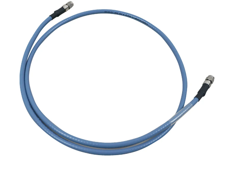
Multiple coaxial cable assemblies with different connector interfaces. Selecting the correct connector type, impedance, and frequency rating is important before installing an RF cable system.
For unterminated cable, the cable outer diameter may be the main clearance limit. For a pre-terminated assembly, the limiting dimension is often the connector, boot, heat-shrink section, or pulling head.
Measure:
- Conduit internal diameter
- Cable maximum outer diameter
- Connector body diameter
- Coupling nut diameter
- Right-angle connector envelope
- Boot or heat-shrink diameter
- Pulling-head diameter
- Pull-box opening
A connector that fits through the straight section may still fail at a coupling, offset, or bend. Inspect the complete route rather than comparing only two catalog dimensions.
Count the Bends Before the Pull
The number and sequence of bends can matter more than the conduit length. A short pathway with several tight changes in direction may be harder than a long straight pull.
Check for:
- Tight entry or exit angles
- Hidden couplings
- Immediate reverse bends
- Small pull boxes
- Existing cables
- Damaged conduit
- Sharp edges
- Misaligned sections
Use the following gate before approving a pre-terminated pull:
“Larger conduit” does not automatically mean “safe pull.” A cable can still twist, scrape against an unprotected edge, or exceed its pulling limit.
Which Pulling Method Protects the Jacket and Shield?
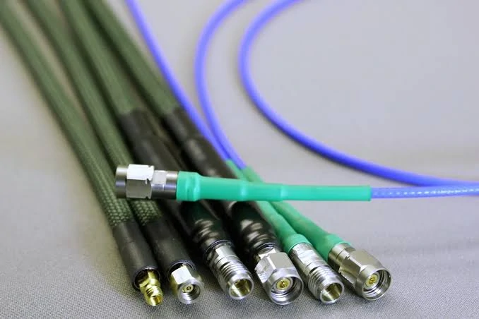
Cross-sectional view of coaxial cable construction. The center conductor, dielectric material, shielding layer, and jacket work together to control impedance, reduce interference, and maintain RF performance.
The pulling method should distribute load into a part of the cable that can safely carry it.
For unterminated cable, installers may use a mesh grip, cable grip, pulling eye, or another method approved for the specific construction. The grip should match the cable diameter and provide enough contact length to avoid concentrating force in one small area.
Do not transfer the entire pulling load into:
- The center conductor
- A connector center pin
- The braid alone
- A foil shield
- A crimp ferrule
- A solder joint
- The connector coupling nut
The rear of a connector is especially vulnerable. Even when the connector remains attached, excessive axial load can disturb the braid contact, stretch the dielectric, rotate the body, or weaken the cable-to-connector transition.
Build a Smooth Pulling Head
A good pulling head has a tapered leading shape, no exposed sharp edges, and no sudden diameter change behind the connector.
Protect the following:
- Threads
- Bayonet features
- Center pin or socket
- Sealing surfaces
- Connector body
- Heat-shrink boot
- Cable exit
The pull line should remain aligned with the cable axis. An offset attachment can force the connector sideways as it enters the conduit.
When several cables are pulled together, stagger the ends rather than making one blunt bundle. Label each cable before wrapping the pulling head, and prevent the cables from crossing inside the bundle.
How Should Coax Cable Pulling Tension Be Controlled?
There is no universal maximum pulling tension for all coaxial cables.
A small flexible cable, a double-shielded RG cable, a corrugated feeder, and a semi-rigid assembly do not carry installation load in the same way. The limit should come from the manufacturer’s data for the exact cable SKU and the intended pulling method.
Confirm:
- Cable manufacturer and model
- Center conductor construction
- Shield construction
- Jacket material
- Installation temperature
- Grip type
- Terminated or unterminated condition
- Loaded bend requirement
Do not estimate the limit from cable diameter alone.
Record Peak Force
Installer feel is not a measurement. For controlled projects, use a dynamometer, calibrated puller, tension-monitoring winch, or another method that records peak force.
Calculate the remaining reserve as:
Pulling reserve = rated pulling limit − measured peak force
A positive result does not automatically confirm that the cable is undamaged, but it shows whether the recorded pull remained within the documented limit.
Pulling-Tension Record
Stop the pull when force rises suddenly. A force spike may indicate a snagged connector, crossed cable, damaged conduit, expanded pulling head, poor reel feed, or a bend that was underestimated during planning.
Do not “pull through it” and inspect only after the cable appears at the other end. Hidden damage may already have occurred.
How Do You Pass Bends Without Twisting or Crushing the Coax?
The cable should leave the reel in the intended payout direction and enter the pathway as straight as practical.
Poor reel alignment introduces twist before the cable reaches the first bend. That twist can accumulate through the route, rotate a pre-installed connector, or create a cable that refuses to lie naturally after the pull.
Assign clear roles:
- Reel operator
- Conduit-entry guide
- Pulling-equipment operator
- Pull-box spotter
- Exit-side inspector
At the conduit entrance, use a bushing, bell, roller, pulley, or rounded guide. Do not drag the jacket across a cut conduit edge.
A cable under tension experiences bending, side pressure, friction, and torsion at the same time. The allowable bend condition during installation may differ from the final static bend radius. Use the cable manufacturer’s loaded and unloaded limits where they are provided.
A reverse S-shaped path deserves attention. If the cable exits one bend and immediately enters another in the opposite direction, consider an additional pull point or a different pulling direction.
For deeper coverage of bend control, add an internal link to the Coax Cable Bend Radius Guide.
Should the Cable Be Terminated Before or After the Pull?
Pulling unterminated cable reduces the maximum pulling diameter and lowers the risk of damaging the connector. It is usually easier when the conduit is small or contains several bends.
The trade-off is field termination. The installer needs the correct stripping dimensions, ferrule, center contact, crimp tooling, soldering process where applicable, and inspection method. A connector that looks acceptable may still have poor braid contact or unstable high-frequency performance.
Factory-terminated cable assemblies offer controlled connector geometry and can be tested before shipment. They are useful for precision RF systems, phase-sensitive paths, high-frequency assemblies, and projects requiring documented VNA results.
They are harder to pull through restrictive pathways.
Termination Timing Matrix
| Project condition | Before pulling | After pulling |
| Small conduit | Higher risk | Preferred |
| Several tight bends | Higher risk | Preferred |
| Factory VNA report required | Preferred | Requires field verification |
| No field termination tools | Preferred | Not practical |
| Connector larger than conduit | Not possible | Required |
| Phase-matched assembly | Preferred | Difficult |
| Open cable tray | Suitable | Suitable |
| Easily accessible equipment room | Suitable | Suitable |
| Unexpected force spike | Yes / No | |
| Cable rotation observed | Yes / No | |
| Final decision | Pass / Inspect / Replace |
When pulling terminated coax cable, protect the connector and make sure the load bypasses the coupling nut, center contact, and cable termination.
After the pull, remove the protection and inspect the center contact position, threads, coupling mechanism, sealing surfaces, connector rotation, and cable exit.
How Should the Route Be Secured After Pulling?
Release temporary pulling tension before installing permanent supports. The cable should settle into a natural path rather than being clamped while stretched.
No connector should carry the weight of a vertical cable section. Transfer that load to the enclosure, mast, tray, or building structure.
Supports should match the finished cable diameter. An oversized clip may allow movement; an undersized clamp may flatten the jacket or disturb the coaxial geometry.
Check these locations after tightening every support:
- First bend behind the connector
- Clamp exit
- Panel entry
- Service loop
- Enclosure cover
- Crossing with another cable
- Vertical transition
Cable ties are easy to overtighten. The jacket may show no immediate cut, yet the dielectric underneath can still be compressed.
Add internal links to the Coax Cable Clips and Clamp Guide and the Coax Cable Strain Relief Guide where support spacing and connector load are discussed.
Label both ends and major route transitions. A useful label identifies the source, destination, system, cable ID, and related test record.
How Do Outdoor and Building Pathways Change the Plan?
“Outdoor cable” is not a complete environmental specification.
The route may require resistance to ultraviolet exposure, moisture, standing water, chemicals, vibration, abrasion, or temperature extremes. Wet conduit should be treated as a wet location rather than assumed to remain dry.
Outdoor entries should prevent water from following the cable into equipment. Common controls include a drip loop, downward-facing entry, sealed bulkhead, weatherproof connector treatment, drainage, and suitable support hardware.
Do not create a tight drip loop. It still needs to respect the cable’s minimum bend radius.
For building pathways in the United States, verify the enforced electrical code edition, cable listing, pathway requirements, support method, separation rules, grounding provisions, and local inspection requirements. The current NFPA 70 edition is the 2026 NEC, but enforcement and adoption vary by state and local jurisdiction. The Authority Having Jurisdiction remains the project reference.
This article does not replace a code review. The cable may be electrically suitable for the RF path and still be unsuitable for the building space.
How Should Power Cables and RF Coax Share the Route?
Identify nearby AC mains, motor wiring, switching supplies, variable-frequency drives, battery cables, high-current DC buses, ignition wiring, relays, and contactors.
Do not place coax where power-cable weight rests on it or where the jacket rubs against tray edges. Avoid shared fasteners that crush one cable while supporting another.
A fixed separation distance cannot be applied to every U.S. installation. Requirements depend on the adopted code, circuit classification, cable listing, raceway construction, barriers, grounding arrangement, and local authority.
Where crossings cannot be avoided, document:
- Crossing location
- Parallel run length
- Nearby power-circuit type
- Barrier or separate pathway
- Grounding arrangement
- Post-installation noise test
- Alternative route considered
Crossing at a more direct angle may reduce the length of close parallel exposure, but mechanical protection and code compliance still need to be checked.
What Checks Catch Damage Before the Link Goes Live?
Inspect the complete route before closing walls, ceilings, trays, or equipment covers.
Look for:
- Kinks
- Flattened sections
- Jacket cuts
- Abrasion
- Crushed cable
- Unsupported weight
- Sharp bends
- Rotated connectors
- Damaged threads
- Missing labels
- Incorrect clamps
Check center-conductor continuity and shield continuity separately. Then verify isolation between center and shield.
Continuity alone is not an RF acceptance test. A cable may remain electrically continuous after its dielectric or shield geometry has been damaged.
Lightly move accessible sections while watching the meter or RF trace. A result that changes with normal movement may indicate a weak termination, fractured conductor, damaged shield, loose connector, or over-stressed bend.
Quarantine a cable with a permanent kink, crushed jacket, connector damage, unknown pulling-force exceedance, intermittent measurement, or unstable RF result. Do not release it because the connected radio still appears to transmit.
Which RF Tests Close the Installation Job?
Compare the installed result with the original loss budget rather than testing against an improvised limit after the work is complete.
At minimum, record:
- Final cable length
- Frequency range
- Expected insertion loss
- Measured insertion loss
- Connector count
- Adapter count
- Test configuration
- Remaining system margin
When both ends are accessible, a VNA can be used to measure S11 and S21 across the required frequency band. Record return loss or VSWR, insertion loss, band-edge performance, and the worst point in the sweep.
Do not save only one favorable marker screenshot. The acceptance record should show:
- Start and stop frequencies
- Test reference planes
- Calibration method
- Adapters used during testing
- Worst S11 or return loss
- Worst S21 or insertion loss
- Instrument identification
- Test date
- Technician
IEC 61196-1-100:2022 provides general requirements and conditions for electrical tests on coaxial communication cables. Project-specific limits still need to come from the cable specification, assembly drawing, equipment requirement, or approved inspection plan.
For additional test interpretation, add an internal link to the Insertion Loss Guide.
Lock the Installation Into the Work Order
The work order should contain enough information for another technician to repeat or inspect the installation without guessing.
Preserve installation photographs, pulling-force records, connector inspection results, continuity measurements, VNA plots, repair details, and final approval.
An as-built drawing should show pull boxes, bulkheads, grounding points, service loops, outdoor transitions, and stable route reference points. “Runs above the ceiling” is not enough for future maintenance.
FAQ
Can a pre-terminated SMA cable be pulled through conduit?
Yes, but only when the protected connector and pulling head fit through every opening and bend. The pulling load should not be carried by the SMA coupling nut, center contact, or cable termination. Verify connector clearance, pulling tension, and bend conditions before starting.
How much extra coax should be left at each endpoint?
Leave enough length for connector access, equipment movement, service work, strain relief, bend-radius control, and any required drip loop. The allowance should be planned. Avoid storing excessive cable as a tight or uncontrolled coil.
Can different coax sizes be pulled through the same conduit?
They may be pulled together when conduit capacity, total pulling load, grip arrangement, cable identification, connector protection, and bend limits are controlled. The cables should not cross or transfer concentrated load into one another inside the pulling bundle.
When should newly installed coax be rejected?
Reject or quarantine the cable when it has a permanent kink, crushed section, damaged connector, failed isolation, unknown pulling-force exceedance, unstable S11 or S21, or a measurement that changes during light movement.
Final Installation Note
A successful coax cable installation is not defined by getting the cable from one end of the route to the other.
The finished path should meet its mechanical limits, environmental requirements, impedance plan, and RF loss budget. Specify the exact cable model, connector interfaces, route conditions, pulling limit, bend requirement, and acceptance tests before ordering. That information prevents field installers from making RF decisions with only a tape measure and a continuity tester.
