
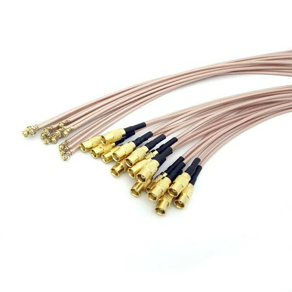
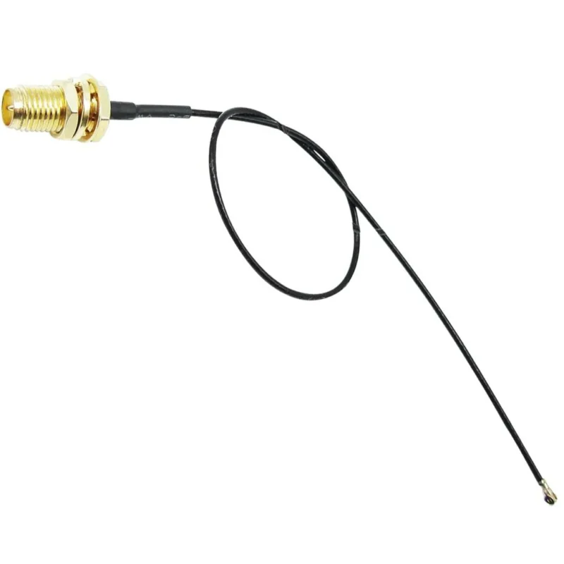
A batch of miniature RF cable assemblies manufactured with thin micro coax cables and gold-plated connector interfaces. These assemblies can be configured for wireless modules, internal antennas, GPS devices, IoT equipment, and compact RF systems.
How Should You Select a Micro Coax Cable for Compact RF Designs?
Choosing a cable for a compact RF product is usually not difficult at the beginning of a project.
The difficulty appears when the mechanical design becomes fixed.
A connector has already been placed on the PCB. The antenna position cannot move. The enclosure leaves only a narrow channel for routing. At this stage, the cable diameter and bending performance start affecting the entire design.
This is where micro coax cable is often considered.
Unlike larger coaxial cables used for external connections, miniature coax cables are mainly used inside equipment where space is limited.
Engineers who are selecting a cable assembly often compare different coaxial structures first. A basic understanding of coaxial cable design can help when reviewing options in an RF cable guide.
What makes micro coax cable different from standard coaxial cable?
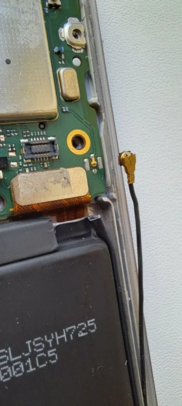
The biggest difference is size.
A standard coaxial cable has enough internal space for stronger mechanical construction. A micro coaxial cable works with much tighter dimensions.
Inside the cable, every layer has less room:
- The center conductor becomes smaller.
- The insulation thickness is reduced.
- The shielding structure becomes more compact.
This allows the cable to fit into smaller products, but it also means the manufacturing process requires better control.
For example, a cable routed inside a wearable device may need to pass around batteries, shields, and mechanical supports. A small change in cable diameter can decide whether the assembly process is smooth or difficult.
Another point engineers often consider is flexibility.
Which parameters should be checked before choosing a micro coax cable?
Cable diameter is usually the first specification people look at.
It should not be the only one.
A practical selection normally starts with the working environment:
| Item | Selection Consideration |
| Diameter | Available installation space |
| Frequency | Operating RF band |
| Impedance | Matching with RF components |
| Length | Expected signal loss |
| Shielding | Protection against interference |
| Flexibility | Assembly and movement requirements |
For a short connection inside a wireless module, a very thin cable may work well.
For a longer antenna cable, the same size may introduce more loss, especially at higher frequencies.
This is why two cables with similar appearance can behave differently after installation.
The correct choice depends on the complete RF path, not only the cable itself.
Why does cable structure become more important as size decreases?
Miniaturization creates less tolerance for design mistakes.
A coaxial cable depends on the relationship between several layers. The conductor carries the signal. The dielectric maintains spacing.
How Do Cable Diameter and Length Affect Micro Coax Cable Selection?
Why is cable diameter an important factor in compact RF designs?
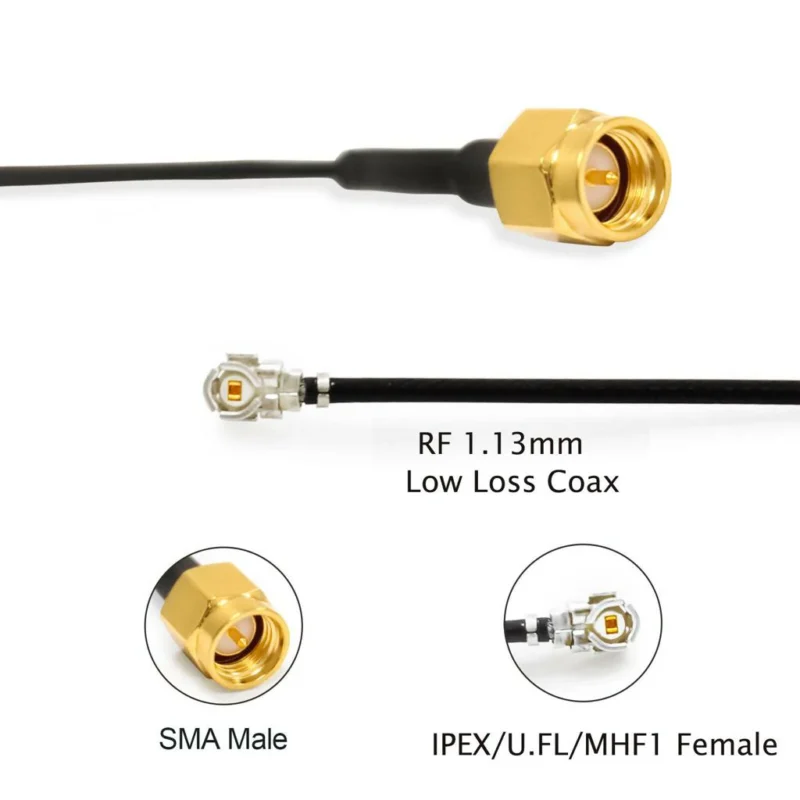
In a compact electronic product, cable routing is often decided after most of the hardware layout has already been completed.
The available space may be limited by the battery, housing structure, heat sink, or other components. At that point, the cable diameter becomes part of the mechanical design.
A micro coax cable with a smaller outer diameter can make installation easier.
For example, a wireless module inside a portable device may require the cable to pass between the PCB and the enclosure wall.
The better choice depends on how the cable will actually be used inside the product.
What happens when the micro coax cable becomes longer?
Cable length is another factor that is easy to underestimate.
During the early design stage, a few extra centimeters may not appear significant. After RF testing, however, the additional length can influence signal performance.
The reason is simple: every section of cable contributes a certain amount of loss.
A longer cable generally means:
- More insertion loss
- Greater signal attenuation
- Higher impact at higher frequencies
For example, an antenna cable inside a small wireless device may only need several centimeters.
How should engineers balance size and RF performance?
There is usually no perfect cable specification.
A very thin cable provides routing advantages.
A larger cable may offer better electrical performance.
The selection depends on the priority of the project.
| Design Situation | Common Selection Direction |
| Small wearable device | Flexible micro coax cable |
| Internal antenna connection | Thin miniature coax |
| Longer RF path | Lower loss cable |
| High frequency measurement | Better controlled RF cable |
| Frequent movement | Stronger mechanical structure |
This balance appears in many RF designs.
A cable used inside a smartphone module, for example, has very different requirements from a cable connecting an external antenna.
The application decides the cable structure.
How Do U.FL and IPEX Applications Use Micro Coax Cable?
Why are U.FL connectors commonly used with micro coax cables?
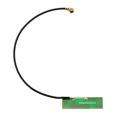
Micro coax cable assembly featuring a compact PCB antenna and miniature RF connector. This type of assembly is commonly installed in WiFi modules, Bluetooth devices, GPS equipment, IoT products, and other embedded wireless systems.
Many wireless modules have very limited PCB space.
A traditional RF connector may physically fit on the board, but it can occupy more area than the design allows.
U.FL connectors solve this problem by providing a very small RF interface.
They are frequently found in:
- WiFi modules
- Bluetooth devices
- GPS boards
- Embedded communication systems
The cable connected to a U.FL connector is usually a miniature coax assembly.
The combination allows engineers to place the antenna in a more suitable position while keeping the RF connection compact.
When selecting a U.FL cable assembly, the connector size is only one part of the decision.
The cable specification also matters:
- Cable diameter
- Length
- Frequency range
- Impedance
- Testing requirements
A cable that fits mechanically may still require RF verification before production.
What should engineers consider when selecting an IPEX cable?
IPEX cable assemblies are widely used in wireless electronics where space is limited.
The name “IPEX” is often associated with small RF connectors used on WiFi modules and wireless cards. In actual applications, the connector and cable work together as one RF path.
A typical selection process includes checking:
| Check Item | Reason |
| Connector version | Prevent mismatch with the board connector |
| Cable type | Match installation requirements |
| Cable length | Control RF loss |
| Frequency range | Ensure operating compatibility |
| Assembly quality | Maintain connection reliability |
This is especially important for products manufactured in large quantities.
A small variation in cable assembly can affect final testing results when thousands of units are produced.
Miniature RF Cable Compatibility Table
| Connector | Common Cable Choice | Typical Usage |
| U.FL | Micro coax cable | Wireless modules |
| IPEX | Micro coax cable | Laptop and WiFi devices |
| MMCX | Small coax cable | Compact RF equipment |
| MCX | Small coax cable | GPS applications |
| SMA | Larger coax cable | External RF connection |
Different connectors may look similar in size, but their intended applications are different.
A connector used inside a wireless module usually focuses on space saving.
A connector used for external testing may require stronger mechanical performance and easier connection.
The cable assembly should always be selected according to the final RF system rather than the connector alone.
Where Does Micro Coax Cable Fit in Real RF Designs?
In RF product development, cable selection often happens later than expected.
The antenna location has already been decided. The PCB drawing has passed review. The enclosure is close to final.
Then a problem appears:
The RF connection needs to pass through a space that was not designed for a conventional cable.
This situation is common in compact wireless products.
A larger coax cable may provide good electrical performance, but it can be difficult to route inside a small enclosure. The bending radius may be too large, or the cable may interfere with nearby components.
A micro coax cable solves this type of mechanical limitation.
It allows designers to keep the RF connection while reducing the space needed for installation.
Typical examples include:
- Wireless communication modules
- GPS tracking products
- Industrial IoT devices
- Portable RF equipment
- Embedded antenna systems
The important point is that cable size is only one part of the design.
The final RF result depends on the entire connection:
Cable → Connector → Antenna → RF circuit
Why is micro coax not always the replacement for larger coax?
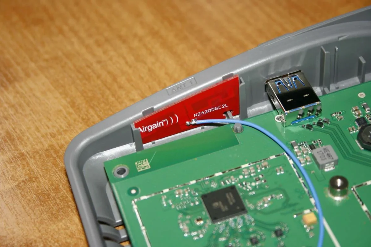
A common misunderstanding is that smaller cable technology is always an upgrade.
In reality, different cables solve different problems.
The first one may prioritize size.
The second one may prioritize signal loss and durability.
Selecting the cable according to the actual environment usually leads to better results than selecting based only on diameter.
How Are Micro Coax Cables Used in Wireless and Navigation Products?
What role does micro coax play inside wireless modules?
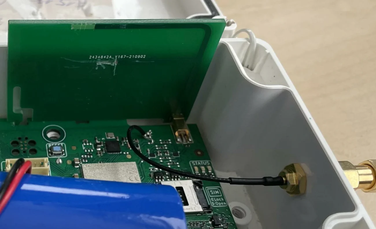
Wireless modules often have one limitation:
The best antenna position is not always next to the RF chip.
Moving the antenna improves product design, but it creates a connection problem.
The cable needs to travel through the available internal space without introducing unnecessary loss.
This is where miniature RF cable assemblies are commonly used.
For high-volume products, this becomes especially important because small differences can appear across thousands of units.
Why are GPS and GNSS applications sensitive to cable selection?
Navigation products often deal with weaker RF signals.
The antenna may be installed in a location with better reception, while the processing board remains somewhere else.
The cable connecting them needs to maintain the signal path without adding unnecessary loss.
In these applications, engineers normally pay attention to:
- Cable attenuation
- Shielding performance
- Connector quality
- Cable routing
A short cable with good construction can perform better than a longer cable with unnecessary routing.
The physical design and RF design need to work together.
Why do IoT products often use miniature RF assemblies?
IoT devices usually combine many functions into a small housing.
Inside one enclosure, there may be:
- Communication module
- Battery
- Sensor
- Control circuit
The available space around the RF section is limited.
A micro coax assembly allows the antenna position to be adjusted without redesigning the whole device structure.
This flexibility is one reason miniature RF cables are common in smart sensors, monitoring equipment, and connected devices.
What Should Be Confirmed Before Ordering Micro Coax Cable Assemblies?
What details affect the final cable assembly?
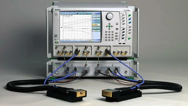
Laboratory RF test setup used to evaluate micro coax cable assemblies. Electrical testing can help verify insertion loss, return loss, impedance consistency, connector performance, and signal stability before cable assemblies are approved for production.
For standard cable products, ordering may only require a part number.
Custom assemblies usually require more information.
Before production, it is better to confirm:
| Item | Information Needed |
| Connector type | U.FL, IPEX, SMA, MMCX, MCX |
| Cable size | Required diameter |
| Cable length | Finished assembly length |
| Frequency | Working frequency range |
| Impedance | 50Ω RF system |
| Testing | Required RF inspection |
Many assembly problems come from missing information at the beginning.
For example:
A connector may fit mechanically but not match the required RF performance.
A cable may work at low frequency but show higher loss at the actual operating band.
Clear specifications reduce these problems before production starts.
Why are U.FL to SMA cables common in RF testing?
During prototype development, engineers often need to connect miniature RF modules with laboratory equipment.
The module side may use U.FL or IPEX connectors, while the test equipment commonly uses SMA interfaces.
A u.fl to sma cable creates this connection.
This type of cable is usually a development tool rather than a final product component.
How are micro coax assemblies checked before shipment?
A physical inspection can confirm:
- Connector appearance
- Cable length
- Assembly condition
But RF performance requires electrical testing.
For demanding RF applications, testing helps confirm that the finished assembly performs as expected.
FAQ
Can micro coax cable be customized?
Yes. Cable length, connector combination, cable type, and test requirements can be customized according to the application.
Does a smaller cable always have higher performance?
No. Smaller diameter mainly improves installation flexibility. RF performance depends on the complete cable structure and operating conditions.
Which connectors are commonly used with micro coax cable?
U.FL, IPEX, MMCX, and MCX are common choices for miniature RF applications.
