
A BNC connector can still look correct even when the RF connection is wrong.
This happens often during equipment integration. A technician finds an older signal generator with a BNC output and a newer RF module using SMA. The quick solution seems obvious: add a bnc adapter, connect the cable, and continue testing.
The first connection usually works.
The problem may appear later.
A measurement system starts showing unexpected noise. The signal level is different from the previous test. The return loss is higher than expected. Or a production team finds that the adapter used during prototype testing cannot be repeated in a final assembly.
The reason is that an adapter is not only a mechanical part. It becomes part of the RF path.
The interface conversion needs to match:
- connector type;
- male and female interface;
- impedance;
- frequency range;
- cable characteristics;
- application environment.
A BNC adapter used for a low-frequency laboratory connection and a BNC adapter used in an RF measurement chain may look similar, but the requirements are different.
How Do BNC Adapters Solve RF Interface Mismatch Problems?
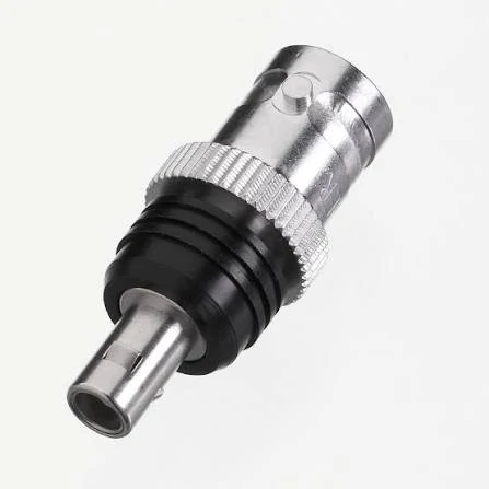
This BNC female adapter is used to connect BNC-based RF equipment and coaxial cables. The adapter helps solve interface compatibility issues while maintaining a compact RF connection structure.
Many RF systems are built with equipment from different generations.
A laboratory may still use instruments with BNC ports because they are convenient and durable. Newer wireless modules, antenna systems, and microwave components often use SMA, TNC, or N-type interfaces.
This creates a common connection problem:
The equipment works, but the interfaces do not match.
A BNC adapter provides a transition between these connector standards without replacing the original equipment or cable assembly.
Typical use cases include:
- connecting a BNC oscilloscope input with an SMA cable;
- adapting older test equipment for new RF modules;
- connecting antenna cables with different connector standards;
- building temporary prototype test links;
- extending existing coaxial cable systems.
For example, a developer testing a wireless module may have:
- SMA female connector on the module;
- BNC output cable from the test instrument.
A sma to bnc adapter allows the two parts to connect.
However, the adapter selection cannot stop at the connector names.
The actual question is:
What is the complete RF path?
A correct selection considers the equipment side, cable side, and operating conditions together.
Which BNC Adapter Details Should Be Confirmed Before Ordering?
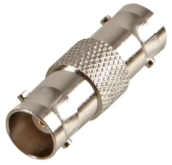
This BNC female to female adapter provides a simple solution for connecting two BNC male cables together. It is widely used in RF testing, laboratory equipment, video systems, and coaxial cable applications.
Many purchasing mistakes happen because the product description looks right but the actual interface is different.
A request such as “need BNC to SMA adapter” is usually not enough information for production.
The supplier still needs to confirm:
- BNC male or BNC female;
- SMA male or SMA female;
- 50Ω or 75Ω system;
- operating frequency;
- cable connection method;
- installation environment.
A BNC plug and BNC jack are not interchangeable. The same applies to SMA interfaces.
The following information is normally required when preparing a BOM:
| Specification | Example | Why It Matters |
| Interface A | BNC female | Defines equipment connection |
| Interface B | SMA male | Defines cable/device connection |
| Impedance | 50Ω | Prevents mismatch problems |
| Frequency | DC–6 GHz | Determines usable range |
| Mounting | Cable type / Bulkhead | Affects installation |
| Application | Test system | Determines performance requirement |
A common mistake is choosing an adapter only because both sides can be connected.
Mechanical compatibility is only the first check.
How Do You Match BNC Adapter Direction With the Actual RF Connection?
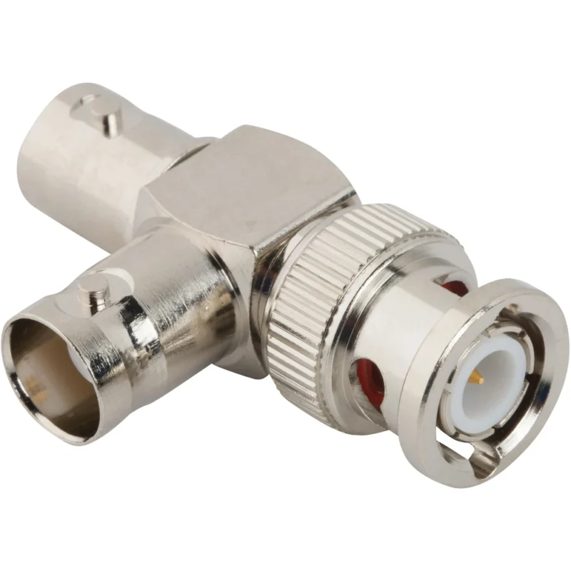
The terms sma to bnc adapter and bnc to sma adapter sometimes create confusion.
They describe the interface conversion, not the direction of signal movement.
An SMA antenna cable connected to a BNC measurement port may require an SMA-to-BNC conversion.
Where Are BNC Adapters Commonly Used in RF Systems?
Laboratory Measurement Equipment
BNC interfaces remain common on:
- oscilloscopes;
- function generators;
- signal generators;
- frequency counters;
- older RF instruments.
For these applications, users often search for an oscilloscope adapter or test equipment adapter.
The main concern is not only whether the adapter fits.
Measurement systems are sensitive to additional transitions.
An adapter may introduce:
- additional insertion loss;
- impedance discontinuity;
- higher reflection;
- measurement variation.
For basic signal observation, the effect may be small.
For calibrated measurements or higher-frequency testing, the adapter should be selected with more attention.
RF Modules and Antenna Systems
In wireless development, SMA connectors are widely used because of their compact size and RF capability.
A bnc connector adapter can help connect SMA-based modules with existing laboratory equipment.
Common applications include:
- antenna testing;
- wireless prototype development;
- RF debugging;
- communication equipment verification.
The important point is matching the adapter to the actual RF environment.
A short adapter used occasionally on a test bench has different requirements from an adapter installed permanently inside equipment.
BNC Adapter Direction Selection Table
The following table helps engineers quickly identify the correct conversion path.
| Adapter Conversion | Common Application | Confirm Before Purchase |
| SMA to BNC | SMA module connected to BNC equipment | SMA gender, impedance |
| BNC to SMA | BNC instrument connected to SMA device | Connector side and cable type |
| BNC to TNC | Field communication equipment | Thread compatibility |
| BNC Female Adapter | Port extension | Mounting structure |
| BNC Cable Adapter | Existing coax cable conversion | Cable impedance |
A BNC adapter is often a small component in the system, but it can affect the entire RF connection chain.
For simple laboratory connections, the selection process may only require interface confirmation.
For RF testing, communication equipment, or repeated production use, the adapter specification should be treated as part of the complete RF design.
Before moving from prototype to production, confirm the connector pair, impedance, frequency range, and cable compatibility first. A correct adapter choice avoids many problems that only appear after the system is already assembled.
How Do 50Ω and 75Ω BNC Adapters Affect System Compatibility?
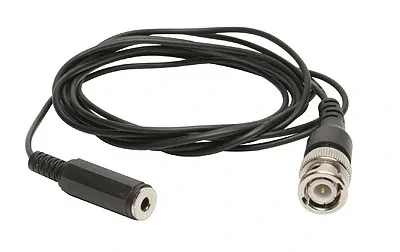
This BNC adapter cable is used for extending or converting coaxial connections between RF devices. It is commonly applied in laboratory testing, signal measurement systems, and communication equipment where BNC interfaces are required.
A BNC adapter can be mechanically correct and still be electrically unsuitable.
This usually happens when the impedance requirement is overlooked.
BNC connectors are used in both 50Ω RF systems and 75Ω video or broadband systems. From the outside, many versions look almost identical. The difference is inside the connector geometry, especially around the center contact dimensions and interface structure.
For purchasing teams, this is one of the easiest mistakes to make.
A request such as “BNC adapter needed” does not tell the supplier enough information. The application determines whether a 50Ω or 75Ω version is required.
A mismatch between impedance values can create:
- signal reflection;
- measurement error;
- standing wave problems;
- unstable RF performance.
The connector may still lock normally. The problem appears in electrical behavior.
When Should You Use a 50Ω BNC Adapter?
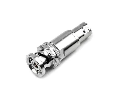
This BNC male adapter is designed for RF interface conversion and provides a reliable connection between BNC equipment and other coaxial connector types. It is suitable for test instruments, communication devices, and RF prototype systems.
A 50 ohm bnc adapter is commonly used in RF and microwave-related applications.
Typical environments include:
- RF test systems;
- communication equipment;
- antenna measurement systems;
- signal generators;
- spectrum analyzers;
- wireless development platforms.
In these systems, the RF path is usually designed around 50Ω impedance.
For example:
A signal generator output:
50Ω BNC port → BNC adapter → SMA cable → RF module
The adapter becomes part of the same transmission line. A mismatched component can influence measurement accuracy, especially when the operating frequency increases.
For laboratory testing, engineers usually check:
- adapter impedance;
- frequency rating;
- insertion loss;
- VSWR;
- connector repeatability.
A low-frequency connection may appear normal even with a poor match. At higher frequencies, the same issue becomes easier to detect.
When Are 75Ω BNC Adapters More Suitable?
A 75 ohm bncadapter is mainly associated with video and broadband signal systems.
Common applications include:
- CCTV systems;
- broadcast equipment;
- video transmission;
- broadband distribution systems.
These systems are designed around 75Ω coaxial cables and interfaces.
Using a 50Ω adapter in a 75Ω video system, or the opposite, may allow physical connection but does not guarantee correct signal transmission.
This is why buyers should include impedance information when requesting:
- BNC adapters;
- coax adapters;
- BNC cable assemblies.
BNC Adapter Impedance Decision Matrix
The following table can help during initial selection.
| Application | Recommended Impedance | Common Choice | Selection Note |
| RF testing | 50Ω | BNC to SMA / BNC to N | Match measurement equipment |
| Wireless communication | 50Ω | RF BNC adapters | Confirm frequency range |
| Antenna systems | 50Ω | Coax RF adapters | Consider cable loss |
| CCTV video | 75Ω | 75Ω BNC adapter | Match video cable |
| Broadcast systems | 75Ω | 75Ω BNC connectors | Avoid mixed impedance |
| Unknown application | Confirm datasheet | Do not guess | Check complete RF path |
A practical rule for procurement:
If the application is unknown, do not select by appearance.
Confirm:
- equipment model;
- cable type;
- signal frequency;
- impedance requirement.
The few minutes spent confirming these details can prevent a much larger problem after installation.
How Do SMA, N, and TNC Conversions Expand BNC Compatibility?
BNC adapters are often used as a bridge between different connector families.
In actual RF environments, BNC rarely exists alone. Engineers often need to connect BNC equipment with SMA modules, N-type antenna systems, or TNC field equipment.
Each conversion has a different purpose.
Connecting BNC Systems With SMA RF Modules
The combination of BNC and SMA is common in laboratories.
SMA connectors are frequently found on:
- RF evaluation boards;
- wireless modules;
- antenna interfaces;
- microwave components.
BNC connectors remain common on:
- test instruments;
- measurement cables;
- signal sources.
A bnc to smaadapter allows these systems to work together without replacing existing equipment.
However, the adapter should match the actual interface.
Common checks include:
- SMA male or female;
- BNC male or female;
- 50Ω requirement;
- operating frequency.
Example:
BNC instrument → adapter → cable → SMA module
may be acceptable for temporary debugging.
But:
BNC instrument → adapter → second adapter → cable → SMA module
creates additional transition points.
Every added connection introduces another possible source of:
- mechanical tolerance error;
- contact variation;
- RF reflection.
Connecting BNC Equipment With N-Type Systems
N-type connectors are common in outdoor RF systems because of their larger structure and environmental capability.
Applications include:
- antenna systems;
- wireless infrastructure;
- outdoor communication equipment.
A BNC to N adapter may be used when connecting laboratory equipment with field-installed RF systems.
The main points to verify are:
- impedance;
- frequency range;
- weather requirements;
- cable type.
For outdoor systems, connector conversion is only one part of the design.
Extending BNC Connections Into TNC Environments
TNC connectors are similar in appearance to BNC but use a threaded coupling mechanism.
This makes TNC more suitable for applications involving:
- vibration;
- transportation equipment;
- field communication systems.
A bnc to tncadapter allows equipment using different locking methods to connect.
The difference is not only mechanical.
Threaded coupling can provide better resistance against accidental loosening compared with bayonet locking.
For mobile equipment, the installation environment should influence adapter selection.
How Should You Select a BNC Adapter for Test Equipment?
Test equipment creates a special requirement because the adapter becomes part of the measurement setup.
A user may not notice a problem during basic signal checking. However, when performing accurate RF measurements, small changes can affect the result.
Before selecting an adapter for testing, confirm three areas.
Check the Equipment Ports First
Identify:
- input port;
- output port;
- connector gender;
- impedance;
- bandwidth requirement.
For example:
A spectrum analyzer with a 50Ω BNC input should not automatically use any available BNC adapter.
The adapter should match the instrument specification.
Consider Measurement Accuracy
An adapter introduces another RF interface.
Possible effects include:
- insertion loss increase;
- additional reflection;
- VSWR change;
- repeatability variation.
This becomes more noticeable when:
- frequency increases;
- cable length increases;
- multiple adapters are connected.
A simple continuity test cannot verify these factors.
Continuity confirms that the electrical path is connected.
It does not confirm RF performance.
Use Fixed Conversion Solutions for Repeated Testing
For occasional bench testing, a standard adapter is often enough.
For production testing, a fixed solution is usually better.
Examples:
- dedicated BNC-SMA test cable;
- labeled adapter set;
- controlled cable length;
- defined inspection standard.
This reduces operator variation.
A common production issue is that engineers develop a prototype using one adapter combination, then production uses another because the original parts are unavailable.
The equipment still connects, but the measurement conditions have changed.
BNC Adapter Test Equipment Selection Checklist
Before adding a BNC adapter into a test setup, verify:
| Check Item | Requirement |
| Connector Type | BNC interface confirmed |
| Gender | Male/Female verified |
| Impedance | 50Ω or 75Ω confirmed |
| Frequency Range | Suitable for application |
| Cable Compatibility | Matching cable type |
| Mounting Method | Correct installation style |
| Measurement Need | Defined accuracy requirement |
| Repeat Usage | Consider fixed assembly |
A BNC adapter is a small component, but in RF testing it should be treated as part of the measurement chain.
The correct choice depends on the complete system rather than the connector label alone.
In the next section, we will continue with cable compatibility, installation limitations, adapter testing methods, supplier selection, and practical purchasing guidance.
Why Can the Cable Choice Change the Result of a BNC Adapter Connection?
A BNC adapter may be the smallest component in the connection, but it is rarely the only factor affecting the RF path.
During prototype testing, engineers often focus on the connector transition first:
“Can this BNC port connect to an SMA device?”
Once the answer is yes, the adapter is usually considered solved.
The problem is that the cable behind the adapter is still carrying the signal.
A BNC adapter connected with a short laboratory jumper may behave differently from the same adapter installed with a longer cable routed through equipment.
The difference can come from:
- cable type;
- cable length;
- bending condition;
- shielding structure;
- connector termination.
This is why RF engineers usually specify the complete assembly rather than only the adapter model.
A more useful description looks like this:
BNC female → SMA male → RG316 cable → 1 meter → 50Ω RF module
instead of simply:
BNC to SMAadapter
The second description identifies the connector but leaves too many variables open.
Match the Adapter With the Cable Before Assembly
Coaxial cables are not interchangeable just because they use the same connector.
RG58, RG59, RG6, and RG316 are common examples.
They may all appear in BNC-related applications, but their construction is different.
RG58 is often selected for general RF connections where a relatively strong cable structure is needed.
RG59 and RG6 are more common in 75Ω video or broadband applications.
RG316 is frequently used inside equipment because the smaller diameter makes routing easier.
That difference affects connector selection.
A connector designed for a larger cable may not clamp correctly on a smaller cable. The connection may look acceptable from the outside but the mechanical support is not the same.
| Cable | Common Use | Detail to Confirm |
| RG58 | General RF connections | Cable diameter and termination method |
| RG59 | Video applications | 75Ω compatibility |
| RG6 | Broadband systems | Connector size matching |
| RG316 | Compact RF wiring | Strain relief and cable support |
A supplier receiving only “BNC adapter required” usually still needs additional information.
The missing details are often:
- what cable is being used;
- whether the cable already exists;
- whether the adapter is mounted inside equipment;
- whether the connection will be moved frequently.
These questions are not paperwork. They usually determine whether the finished assembly works as expected.
When Is a BNC Adapter Better Than Making a New Cable?
There is no single answer because the application decides.
For a laboratory engineer testing different modules, adapters are convenient.
A technician may need to connect:
- a BNC signal source;
- an SMA evaluation board;
- an N-type antenna;
- different measurement cables.
Replacing cables every time would slow down development.
In this situation, a coax adapter is a practical choice.
The situation changes in production.
If operators repeat the same connection hundreds of times, a fixed cable assembly may create fewer problems.
After optimization, the same connection may become:
BNC-SMA cable assembly
The second approach reduces the number of parts handled by operators.
It also makes replacement easier because the assembly has a fixed specification.
The decision is usually not about which option is better.
It is about whether the system needs flexibility or repeatability.
How Should BNC Adapters Be Tested Before Use?
A connector that passes a basic electrical check is not automatically ready for every RF application.
The inspection method depends on where the adapter will be used.
For general equipment connections, checking the mechanical condition may be enough.
For RF measurement systems, additional tests are normally considered.
Check the Mechanical Interface First
The first inspection does not require special equipment.
Look at:
- BNC locking movement;
- center contact position;
- connector surface condition;
- thread or coupling damage;
- fit after repeated mating.
A loose connection can create intermittent problems.
This is especially common in environments where operators frequently connect and disconnect cables.
A part that works during incoming inspection may behave differently after months of use.
Verify RF Performance When the Application Requires It
Continuity testing is useful, but it only confirms that the circuit path is connected.
It does not show:
- reflection level;
- insertion loss;
- impedance behavior.
For RF applications, engineers may check:
- VSWR;
- return loss;
- insertion loss.
A VNA test is usually considered when the adapter is part of a sensitive measurement path.
The required test level should match the application.
There is little value in applying the same inspection standard to a simple low-frequency connection and a GHz-level RF measurement fixture.
BNC Adapter Installation Review Checklist
Before a BNC adapter enters a project, the following information should be confirmed.
| Item | Check Point |
| Interface | Correct BNC conversion |
| Gender | Male/female combination |
| Impedance | 50Ω or 75Ω |
| Cable | Compatible cable type |
| Frequency | Within required range |
| Installation | Suitable mounting method |
| Testing | Required RF inspection defined |
| Documentation | Model and specification recorded |
This type of checklist is simple, but it prevents common ordering mistakes.
Many issues happen because the adapter was correct according to the purchase order, but the purchase order did not contain enough technical information.
What Should Be Prepared Before Buying BNC Adapters?
A good RF inquiry usually includes more than the connector names.
For a standard request, suppliers normally need:
| Information | Example |
| Connector side A | BNC female |
| Connector side B | SMA male |
| Impedance | 50Ω |
| Frequency range | DC–6 GHz |
| Quantity | Sample / production |
| Application | Test equipment |
| Cable requirement | RG316 cable |
| Inspection | Standard or RF test |
This information helps avoid unnecessary replacements later.
Two products can both be called “BNC to SMA adapters” and still have differences in:
- internal structure;
- frequency capability;
- material;
- plating;
- assembly method.
The name alone is not enough for a production decision.
FAQ
Can a BNC adapter solve an impedance mismatch?
No. The adapter changes the physical interface. The RF system still needs the correct impedance throughout the signal path.
Should I use an adapter or a complete RF cable assembly?
Adapters are useful when flexibility is needed. Cable assemblies are often preferred when the connection is fixed and repeated.
Does continuity testing prove an adapter is good?
No. Continuity only confirms electrical connection. RF performance requires additional evaluation when accuracy matters.
What information should be included when ordering BNC adapters?
Include both interfaces, gender, impedance, frequency range, cable information, quantity, and application details.
Final Practical Note
A BNC adapter is easy to underestimate because it is physically small.
In an RF system, however, every transition becomes part of the signal path.
The safest way to select an adapter is to describe the complete connection:
- what equipment is connected;
- what cable is used;
- what frequency is involved;
- what impedance is required;
- how often the connection will be used.
For occasional laboratory work, a standard adapter may solve the problem quickly.
For production testing or long-term equipment integration, the better solution may be a controlled cable assembly with defined specifications.
The difference is not the connector itself.
It is how the complete RF connection is designed.
