
A customer received the first batch of wireless devices and found that the antenna connection was unstable.
The connector was correct. The cable length matched the drawing. The supplier had even completed a continuity test before shipment.
The problem appeared during RF testing.
At lower frequencies, the assembly looked normal. The cable type was not the same as the one used during the prototype stage.
This type of mistake is common in RF sourcing.
Antenna cables often look simple from the outside. A coaxial cable with an SMA connector on both ends may appear interchangeable, but the internal construction, impedance control, shielding method, and attenuation characteristics can make a noticeable difference in the final system.
For engineers and buyers, selecting an antenna cable is not only about finding a connector that fits.
How Do Antenna Cables Connect RF Systems With Antennas?
In a wireless product, the antenna cable sits between the RF circuit and the antenna.
The cable has to carry the RF signal while maintaining the electrical conditions required by the system.
A small change in the cable can affect several parameters:
- Signal attenuation
- Impedance matching
- Return loss
- VSWR
- Mechanical installation
For low-frequency applications, some differences may not immediately appear. In higher-frequency systems, cable selection becomes more sensitive.
A WiFi module, GPS receiver, or IoT controller may use a very short cable inside the enclosure. In this case, flexibility and connector size are often important. An outdoor communication system may require a different approach because the cable route is longer and every meter of attenuation reduces available signal margin.
This is why antenna cable selection usually starts from the application, not from the connector name.
Why Do Wireless Devices Use Antenna Cable Assemblies?
Many RF products do not place the antenna directly on the PCB.
The antenna may need to be located:
- Outside the metal enclosure
- Away from interference sources
- At a better radiation position
- In a separate mechanical area
An antenna cable assembly solves this connection problem by providing a ready-made RF path.
For production buyers, the advantage is consistency.
When cable and connectors are purchased separately, there are more variables during assembly. A different cable diameter may require another connector body. A different termination method may affect repeatability.
A common example is replacing one coax cable with another because both are marked as 50Ω. Electrically they may look similar on paper, but the bending behavior and loss characteristics can be different.
Where Are Antenna Cables Used in Real RF Applications?
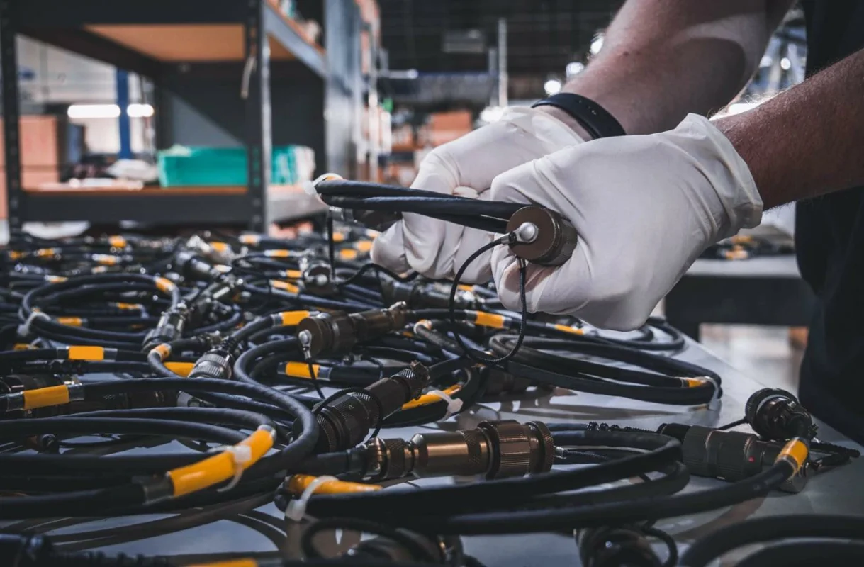
The same antenna cable category can appear in very different products.
Typical applications include:
| Application | Common Requirement | General RF Cable |
| WiFi Router | Compact size, stable RF connection | RF signal transmission between components |
| GPS Equipment | Small diameter, flexible routing | Test systems, modules, microwave equipment |
| IoT Device | Space limitation, custom length | Frequency, loss, measurement accuracy |
| Wireless Gateway | Shielding and installation reliability | SMA, N Type, 2.92mm, 3.5mm, others |
| Outdoor Communication | Lower loss, environmental protection |
A wifi antenna cable is usually selected around the module interface, enclosure space, and antenna location.
A gps antenna cable may need a small coaxial cable because the cable route inside vehicle electronics or tracking equipment is often limited.
For outdoor RF systems, a larger low loss antenna cable may be preferred because cable length becomes a major factor. A cable that works well at 20 cm may not be suitable for a several-meter installation.
How Should Buyers Compare Antenna Cable and General RF Cable?
The term RF cable covers a wide range of products. Antenna cable is one application category within RF cable solutions.
A procurement mistake happens when the cable is selected only by interface.
For example, an SMA cable may connect physically to the device, but the actual requirement may need:
- A specific frequency range
- A certain cable diameter
- A defined bend radius
- Lower attenuation
- Better shielding
The connector only confirms mechanical compatibility. It does not confirm the whole RF performance.
What Information Should Be Included When Ordering an Antenna Cable?
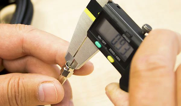
This image shows the dimension inspection of an RF connector using a digital caliper. Connector size, gender, cable fit, and mechanical dimensions are important details when selecting or ordering antenna cable assemblies for RF equipment.
A short description such as:
“Need SMA antenna cable, 1 meter”
is usually not enough for production use.
A supplier normally needs more information:
| Specification | Example |
| Connector A | SMA Male |
| Connector B | SMA Female |
| Impedance | 50Ω |
| Cable Type | RG316 / RG174 / Low Loss Coax |
| Length | 500 mm |
| Frequency | DC–6 GHz |
| Installation | Internal routing |
| Test Requirement | Continuity / VSWR |
This information reduces the risk of receiving a cable that fits mechanically but fails electrically.
For prototype quantities, engineers can often adjust after testing. For mass production, a small difference in cable construction can create repeated problems across hundreds or thousands of units.
How Do You Match Antenna Cable Connectors With RF Equipment?
A replacement request often starts with a connector name.
“SMA cable, 500 mm.”
For a purchasing department, this description may seem enough. For an RF engineer, several details are still missing.
The connector interface only describes the mechanical connection. It does not tell the supplier what cable should be used, how the assembly will be installed, or whether the RF characteristics match the system.
Before selecting an antenna cable, engineers usually check:
- Connector series
- Connector gender
- Polarity
- Cable diameter
- Frequency range
- Installation space
- Required test standard
A cable assembly can physically connect to the equipment and still create problems later.
One example is replacing a small internal WiFi antenna cable. The original assembly uses a thin flexible coax cable because the cable needs to pass around the PCB edge with a limited bending radius. A replacement cable with a larger diameter may have lower loss, but the added stiffness can damage the board connector during assembly.
The electrical specification and mechanical design have to be considered together.
When Does SMA Antenna Cable Become the Practical Choice?
SMA connectors are common in wireless equipment because they provide a threaded connection in a relatively compact size.
They are frequently seen in:
- WiFi modules
- GPS receivers
- RF evaluation boards
- IoT gateways
- Wireless communication devices
However, selecting an SMA antenna cable is not simply selecting an SMA connector.
The cable behind the connector matters.
A small device may require:
- Thin coax cable
- Short bending radius
- Lightweight assembly
- Right-angle connector
A test environment may require:
- Better phase stability
- Lower insertion loss
- More accurate repeatability
The same SMA interface can appear in both situations, but the cable construction is different.
For example, RG174, RG178, and RG316 are all flexible coaxial cable options. Their outside diameter, attenuation, temperature capability, and mechanical behavior are not identical.
A supplier needs the actual application information, not only the connector label.
Why Are N Type Antenna Cables Used More Often Outdoors?
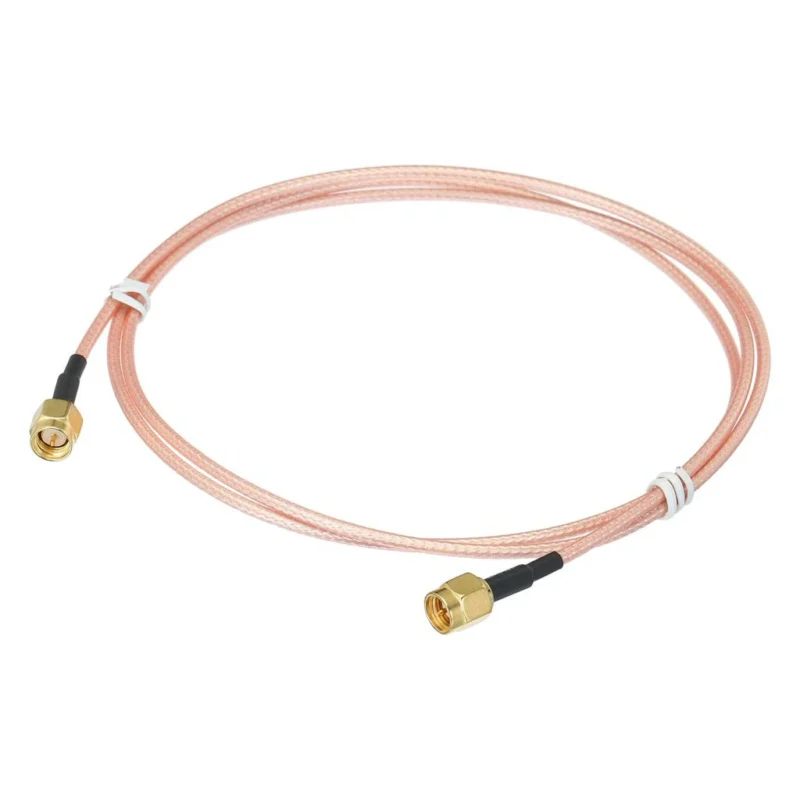
Outdoor antenna connections usually face conditions that do not exist inside electronic products.
The cable may need to handle:
- Longer transmission distance
- Temperature changes
- Rain and humidity
- Mechanical movement
- Repeated installation
This is where N Type antenna cable assemblies are commonly considered.
N Type connectors are widely used for:
- Outdoor antennas
- Wireless base stations
- RF communication links
- Industrial wireless systems
For these applications, the cable selection usually receives more attention than the connector itself.
A 5-meter antenna cable is not simply a longer version of a 30-centimeter cable.
The additional length increases:
- Cable attenuation
- Connector quantity
- Installation complexity
If the operating frequency is high, the loss difference becomes more noticeable.
A cable that works well on a short laboratory setup may not be suitable after installation on a building rooftop or outdoor cabinet.
Which Connector Details Should Be Confirmed Before Ordering?
Many RF sourcing mistakes happen because the connector description is incomplete.
A basic connector confirmation sheet can prevent repeated communication:
| Item | Example Requirement |
| Connector A | SMA Male |
| Connector B | N Female |
| Polarity | Standard SMA |
| Mounting Style | Bulkhead / Cable Mount |
| Cable Direction | Straight / Right Angle |
| Impedance | 50Ω |
| Application | Outdoor antenna |
This information is especially important for custom antenna cable assemblies.
A connector supplier may offer multiple versions that look similar but use different:
- Contact structures
- Insulator designs
- Cable attachment methods
- Mechanical dimensions
The front interface is only one part of the assembly.
How Does Impedance Affect Antenna Cable Selection?
Why Is 50Ω the Common Choice for RF Antenna Systems?
Most wireless RF systems use 50Ω antenna cable.
The reason is not because 50Ω is the only possible impedance. It became widely adopted because it provides a practical balance between transmission loss and power handling.
all parts should be designed around the same impedance.
A mismatch causes part of the RF energy to reflect back toward the source.
Engineers normally check this through measurements such as:
- VSWR
- Return loss
- Insertion loss
A simple continuity check cannot detect these problems.
A cable may pass electrical connection testing and still show poor RF behavior at the working frequency.
Can Two Similar RF Cables Have Different Impedance Behavior?
Yes.
This is one reason cable substitution needs attention.
Two cables may both use:
- SMA connectors
- Similar outer diameter
- Similar length
but have different internal structures.
The following factors affect RF behavior:
| Cable Factor | Possible Effect |
| Dielectric material | Changes electrical characteristics |
| Shield structure | Affects interference protection |
| Conductor size | Influences loss |
| Cable geometry | Affects impedance control |
For purchasing teams, “50Ω coax cable” is a starting point, not a complete specification.
The cable type, operating frequency, and application environment still need to be confirmed.
Antenna Cable Impedance Selection Reference
RF Application Impedance Decision Table
| Application | Common Selection | Notes |
| WiFi antenna connection | 50Ω coax cable | Match wireless module specification |
| GPS antenna cable | 50Ω coax antenna cable | Used for RF receiver paths |
| IoT wireless device | 50Ω flexible cable | Space and routing are important |
| Video transmission | 75Ω cable | Different signal system |
| Unknown replacement cable | Confirm original specification | Avoid connector-only matching |
This table can be used during BOM review when replacing existing antenna assemblies.
How Does Cable Length Change Antenna Cable Performance?
Cable length is often underestimated during product design.
A prototype may use a short cable because the engineer connects the antenna directly beside the RF module.
The actual loss will also include connectors and adapters.
Why Do Some Antenna Systems Need Low Loss Cable?
A low loss antenna cable is usually considered when the cable distance becomes significant.
Typical situations include:
- Outdoor antenna installation
- Long RF connection distance
- Higher frequency operation
- Systems with limited signal margin
A frequent mistake is selecting a cable based only on price and connector type.
A cheaper cable may increase total system loss enough that the antenna location or equipment setting needs to be redesigned.
The cable choice should be evaluated together with the complete RF path.
RF Cable Loss Evaluation Sheet
Information Asset: Antenna Cable Loss Calculation
| Parameter | Example |
| Cable Model | Low Loss Coax |
| Operating Frequency | 5 GHz |
| Cable Length | 3 m |
| Cable Attenuation | ___ dB/m |
| Connector Quantity | 2 pcs |
| Adapter Quantity | ___ pcs |
| Total RF Loss | ___ dB |
The calculation is simple, but it helps prevent a common production issue: adding multiple adapters or extension cables after the original RF design has already been approved.
How Do Cable Construction Details Affect Antenna Installation?
The antenna cable is often selected before the final mechanical design is completely finished.
This creates a common situation.
The RF engineer confirms the electrical requirement first. Later, the mechanical team changes the enclosure, moves the antenna position, or changes the cable routing path.
The cable that worked during testing may no longer fit the final product.
A cable assembly can fail for reasons that have nothing to do with the connector interface.
For compact wireless products, cable structure is usually a compromise between electrical and mechanical requirements.
A smaller cable may be easier to install.
A larger cable may provide lower attenuation.
A stronger shield may improve interference resistance.
The final choice depends on where the cable will actually be installed.
When Does Shielding Become Necessary for an Antenna Cable?
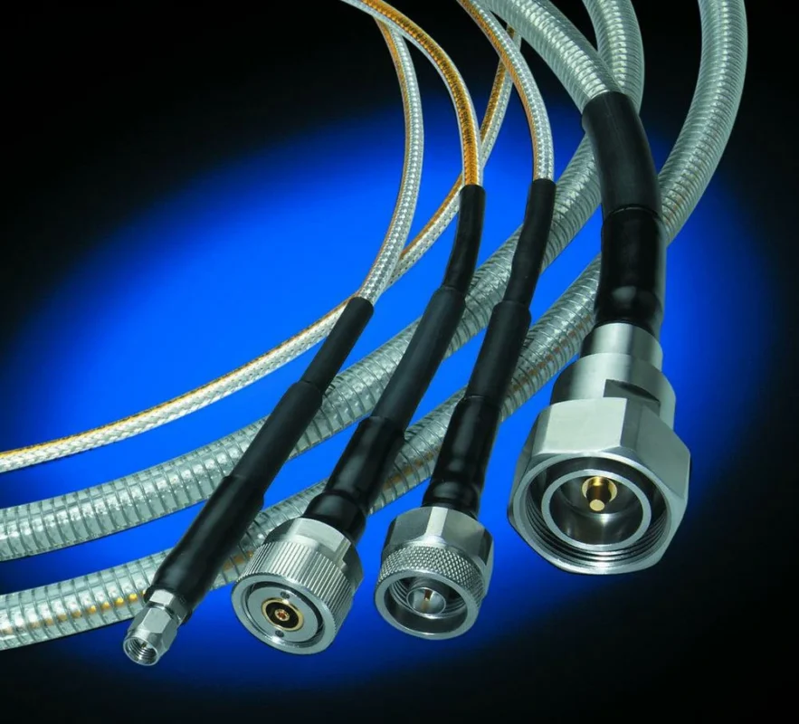
Not every wireless product requires the same shielding level.
A short cable inside a small consumer device may operate correctly with a standard flexible coax cable.
A cable installed near:
- Motor drivers
- Switching power supplies
- Industrial controllers
- High-current wiring
faces a different environment.
In these cases, engineers may consider a shielded antenna cable.
The purpose of shielding is to control unwanted electromagnetic coupling between the RF path and surrounding circuits.
However, shielding should not be viewed as a replacement for correct cable selection.
A shielded cable with the wrong impedance or unsuitable frequency range can still create RF problems.
During supplier communication, buyers usually need to define:
| Requirement | Example |
| Cable Application | Industrial wireless device |
| Environment | High EMI area |
| Cable Type | Shielded coax |
| Impedance | 50Ω |
| Frequency Range | Operating band |
| Installation | Fixed or flexible routing |
This information helps avoid selecting a cable only by appearance.
How Do WiFi, GPS, and IoT Products Use Different Antenna Cable Designs?
The phrase “antenna cable” covers many different products.
A cable used inside a WiFi router and a cable used for a vehicle GPS system may both carry RF signals, but the design requirements are not the same.
Why Are WiFi Antenna Cables Usually Focused on Space and Routing?
A wifi antenna cable is commonly installed between the wireless module and an external antenna.
Typical concerns include:
- Limited enclosure space
- Small connector size
- Short cable length
- Easy assembly
Many WiFi products use compact coax cables with small RF connectors.
The challenge is usually mechanical.
The cable must reach the antenna position without placing excessive force on the PCB connector.
A cable that is electrically acceptable may still create assembly issues if the routing is too tight.
Why Do GPS Antenna Cables Need Attention to Loss?
A gps antenna cable often connects a receiver module to an antenna placed away from the main electronics.
Examples include:
- Vehicle tracking equipment
- Navigation devices
- Positioning terminals
In these products, cable length can become a design factor.
A few centimeters of cable may have little effect.
A longer connection routed through a vehicle or enclosure requires more evaluation.
Engineers usually check:
- Cable attenuation
- Connector quantity
- Operating frequency
- Installation environment
The antenna cable is part of the receiver system, not only a mechanical extension.
What Changes When Antenna Cables Are Used in IoT Devices?
IoT products often combine several constraints:
- Small enclosure
- Wireless communication
- Battery operation
- Cost control
- Large production quantity
A custom antenna cable assembly is common in this situation.
How Should Companies Decide Between Standard Cable and Custom Assembly?
A common question from buyers is:
“Should we buy the cable separately or ask for a finished assembly?”
The answer depends on the production situation.
For laboratory testing, standard cables are often enough.
For repeated manufacturing, a finished antenna cable assembly usually reduces assembly variables.
The difference is mainly control.
With a custom assembly, the specification can define:
| Item | Example |
| Connector Side A | SMA Male |
| Connector Side B | IPEX |
| Cable | RG316 |
| Length | 250 mm |
| Routing | Right angle |
| Inspection | VSWR check |
This gives the production team a clear incoming inspection standard.
A simple decision process can prevent unnecessary customization during early development.
How Should Antenna Cable Assemblies Be Tested Before Shipment?
A cable assembly can look perfect after production.
The connector surface may be clean.
The cable length may match the drawing.
The label may be correct.
But RF performance still needs confirmation when the application requires it.
Which RF Measurements Are Used for Critical Antenna Cables?
For higher requirement applications, additional tests may be specified.
It does not show whether the RF signal is transferring correctly at the operating frequency.
This difference matters more as frequency increases.
Antenna Cable Production Acceptance Checklist
Information Asset: Incoming Inspection Reference
| Check Item | Requirement |
| Connector Interface | Match specification |
| Connector Gender | Confirm |
| Polarity | Verify |
| Impedance | 50Ω / 75Ω |
| Cable Model | Match BOM |
| Cable Length | Match drawing |
| Frequency Range | Application requirement |
| Continuity | Pass |
| VSWR Test | If required |
| Appearance | No damage |
This type of checklist is useful when multiple cable assemblies are purchased from different suppliers.
FAQ
What information should be included in an RF cable purchase request?
A useful request normally includes connector interface, gender, impedance, cable model, length, frequency range, termination method, and test requirements.
Can the same antenna cable be used for WiFi, GPS, and other wireless devices?
Not always.
A WiFi device may need a small flexible cable because the antenna is located inside a limited enclosure. A GPS device may pay more attention to cable loss because the antenna and receiver can be separated by a longer distance.
The connector may be the same, but the cable requirement can change depending on the product design.
When should I use a low loss antenna cable?
A low loss antenna cable is usually a better choice when the cable is long, the frequency is high, or the system has limited signal margin. This is common in outdoor antennas, base stations, communication cabinets, and long-distance RF connections. If the cable route is only a few centimeters inside a device, flexibility may be more important than low loss. For longer installations, every extra meter can increase attenuation.
Can I replace one 50 ohm antenna cable with another 50 ohm cable?
Not always. The same 50 ohm rating does not mean two cables will behave the same in real use. Cable diameter, dielectric material, shielding structure, flexibility, and attenuation can all be different.
Final Purchasing Notes for Antenna Cable Selection
Many RF cable problems start from incomplete specifications.
A request such as:
“Need 1 meter SMA cable.”
may describe the connector, but it does not describe the actual RF requirement.
Before ordering, confirm:
- Equipment interface
- Connector gender and polarity
- Impedance
- Cable type
- Operating frequency
- Cable length
- Installation environment
- Required inspection method
For prototype development, engineers can often adjust after testing.
For production orders, those details should be confirmed before the first batch is released. A small change in cable construction may affect assembly, testing, and final RF performance.
