50 Ohm BNC Terminator Guide: Lab Practices & Signal Integrity Tips
Nov 5,2025
Preface
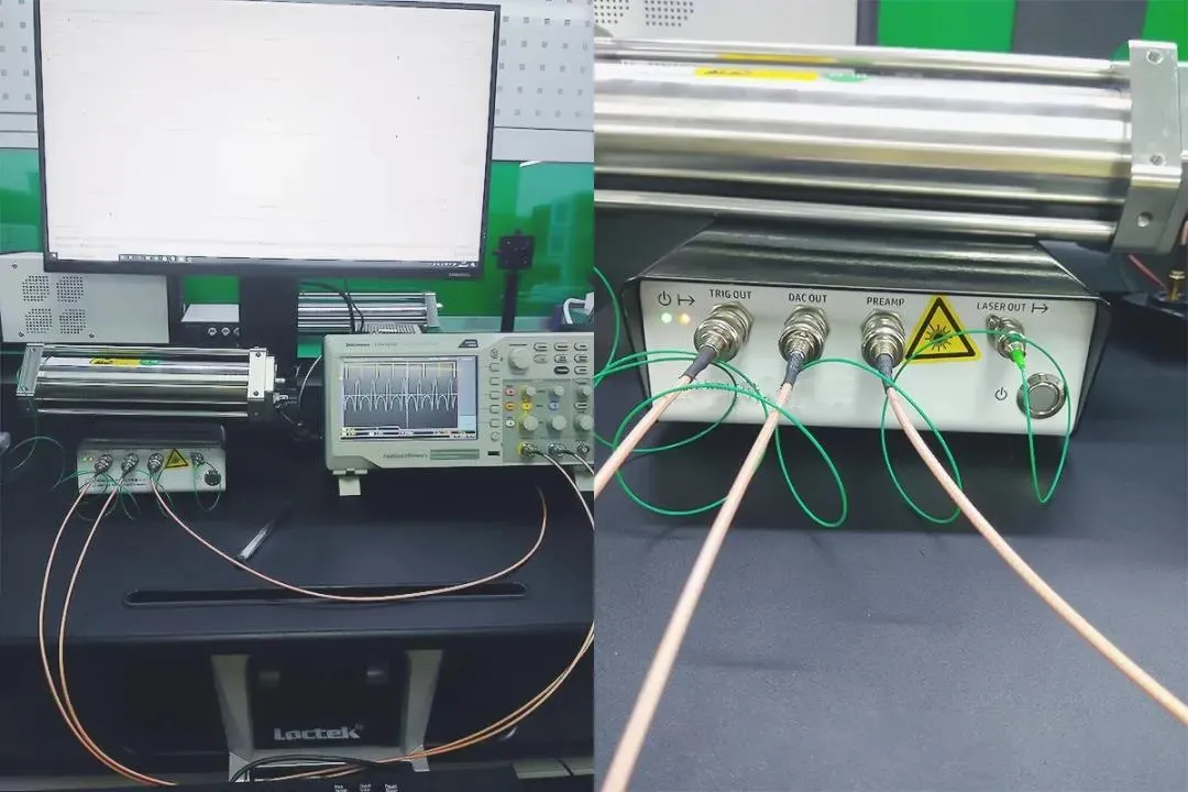
Figure serves as the opening visual element of the document, aiming to immediately capture the reader's attention through a common lab scenario – abnormal waveforms on an oscilloscope – and emphasize the critical importance of high-quality BNC terminators for ensuring accurate measurements.
Every engineer who’s spent time on a lab bench knows the quiet frustration of chasing small reflections that ruin clean waveforms. Most of the time, the culprit isn’t the scope, the cable, or the source—it’s the termination. A single mismatched load can turn a textbook-perfect signal into a jittery mess.
That’s why the humble 50 ohm BNC terminator deserves more respect. It’s the silent guardian of signal integrity, the unseen link that ensures your measurements mean something.
At TEJTE, precision-machined components like the BNC-KF 4-hole flange connector (Part No. 39326) and BNC-KK bulkhead adapter (Part No. 34227) are engineered for real test benches—not just datasheets. They’re rated DC–6 GHz, maintain 50 Ω ± 1.5 Ω, and achieve return loss ≤ 1.2 dB @ 1 GHz, with nickel-plated brass shells and copper contacts that survive thousands of mating cycles.
This guide walks you through the practical side of termination—how to pick the right impedance, connect properly, and check your setup before your next calibration run. Whether you’re measuring fast digital edges or distributing clock references, these small metal pieces quietly make or break your precision.
Which impedance should you terminate—50 Ω or 75 Ω?
In laboratories, 50-ohm BNC has become the default for most test instruments. Oscilloscopes, function generators, and spectrum analyzers all expect to see 50 Ω at their ports. The reason is simple: maximum power transfer and minimum reflection occur when the entire chain—source, cable, and load—shares the same impedance.
In contrast, 75 Ω systems dominate video and broadcast setups, where maintaining accurate voltage levels matters more than power delivery. Mixing the two without correction often leads to invisible mismatches that distort the measurement. Even a small 50/75 Ω mismatch can produce around 1.5 dB return-loss degradation near 1 GHz, which means roughly 15 % reflected power—plenty to corrupt a 1 ns edge.
A real-world example: the TEJTE BNC-KF flange connector holds its impedance tolerance so tightly that engineers can confidently terminate their test ports without recalibrating. Its DC–3 GHz bandwidth, ≤ 1.5 mΩ contact resistance, and 500 V rms voltage limit make it a reliable anchor point in any RF setup. You’ll find this type of connector in precision measurement instruments, network analyzers, and intelligent communication equipment that demand consistent impedance.
Match the entire chain: RF test (50 Ω) vs video/CCTV (75 Ω)
A measurement setup is only as good as its weakest link. If you use a 75 Ω video analyzer with a 50 Ω signal generator, reflections will sneak in no matter how clean the cables look. The fix isn’t a simple BNC tee; it’s a proper impedance bridge.
Here’s what seasoned engineers do:
- RF test setups: keep every path 50 Ω, from source to terminator.
- Video systems: run true 75 Ω coax such as RG59/RG6, with dedicated 75 Ω terminators.
- Mixed chains: use a 75 Ω to 50 Ω matching pad (often around –5.7 dB attenuation) to maintain proper power flow.
In a typical rack, you might see a TEJTE BNC-KK bulkhead adapter feeding a distribution panel. This connector’s DC–6 GHz performance and PTFE dielectric keep insertion loss below 0.05 dB @ 1 GHz—so even when chained between multiple instruments, it doesn’t steal amplitude or skew phase.
For technicians wiring shared benches, it helps to label ports clearly. Mixing 50 Ω and 75 Ω gear without documentation often results in “mystery ripple” on scope traces. As discussed in TEJTE’s BNC 50 Ohm vs 75 Ohm Impedance Guide, consistency across the chain is the only way to keep return loss predictable.
Can your source actually drive the terminator’s power rating?
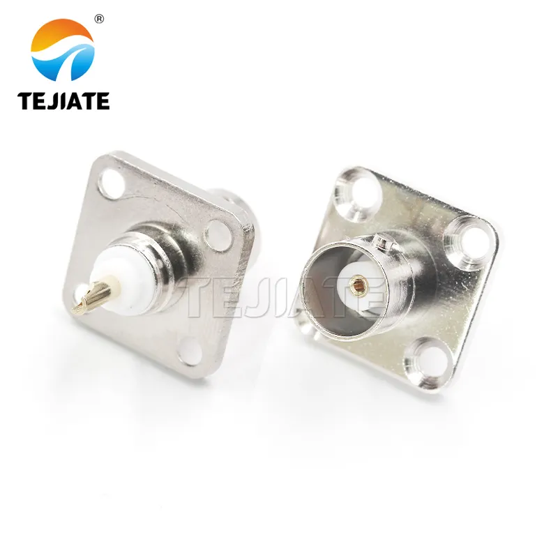
Figure appears as an example in the "Can your source actually drive the terminator's power rating?" section. It showcases a durable and high-performance connector from TEJTE, whose design and specifications directly support the discussion in the context regarding power handling, thermal management, and long-term reliability.
A 50 ohm BNC terminator may look tiny, but it still needs to dissipate heat from the generator’s output. If your source delivers more than the terminator’s rated wattage, distortion and thermal drift can sneak in long before the connector feels warm to the touch.
To estimate safety margins, remember the quick rule:
[ P = \frac{V_{\text{rms}}^2}{R} ]
or, when your signal generator lists Vpp, use
[ V_{\text{rms}} = \frac{V_{\text{pp}}}{2\sqrt{2}} ]
A 2 Vpp sine wave into 50 Ω produces only 10 mW, but at 20 Vpp you’re already near 0.8 W—enough to push many compact terminators close to their limit. Continuous wave (CW) testing or wide-duty-cycle pulse trains add even more thermal load.
TEJTE’s BNC-JKKK cross adapter (Part No. 12666) and BNC-KF 4-hole flange connector (Part No. 39326) both handle up to 1 W @ DC–4 GHz, tested within –45 °C to +125 °C. That margin is more than enough for typical oscilloscope and signal-generator ports, but if you’re distributing reference clocks or driving multiple paths through a tee, consider a 2 W feed-through design.
When setting up long-duration RF tests, always double-check your terminator’s wattage rating, not just its impedance. A low-cost unit can fail quietly, shifting impedance above 60 Ω after extended heat exposure—a problem that will mislead return-loss readings for hours.
How do you set a realistic return-loss target by frequency?
Return loss (RL) is one of those specs that engineers quote often but measure rarely. Yet, it defines how “clean” your signal reflections really are. The higher the RL in decibels, the smaller the mismatch between your source and terminator.
Here’s the quick math reference used on every RF bench:
[ \Gamma = \frac{Z_L – Z_0}{Z_L + Z_0} ]
[ RL(dB) = -20 \log_{10} |\Gamma| ]
[ ML(dB) = -10 \log_{10}(1 – |\Gamma|^2) ]
| RL (dB) | Reflection | Mismatch Loss | Category |
|---|---|---|---|
| ≥ 25 dB | < 0.056 | < 0.15 dB | Excellent |
| 20 – 25 dB | 0.056 – 0.1 | 0.15 – 0.45 dB | Acceptable |
| < 20 dB | > 0.1 | > 0.45 dB | Needs review |
The TEJTE BNC-KF connector family demonstrates why good RL specs matter. With ≤ 1.2 dB VSWR @ 1 GHz (equivalent to ~25 dB RL), these components deliver green-zone matching for test cables up to 6 GHz. Combined with RG58 or RG316 coax, the total chain can easily stay below 1.3:1 VSWR—enough for precision RF calibration.
If you need help balancing power and reflection in complex setups, check the RF Coax Cable Guide on tejte.com, which details how cable attenuation and VSWR stack across frequency.
Connect and verify a 50 Ω BNC termination step by step
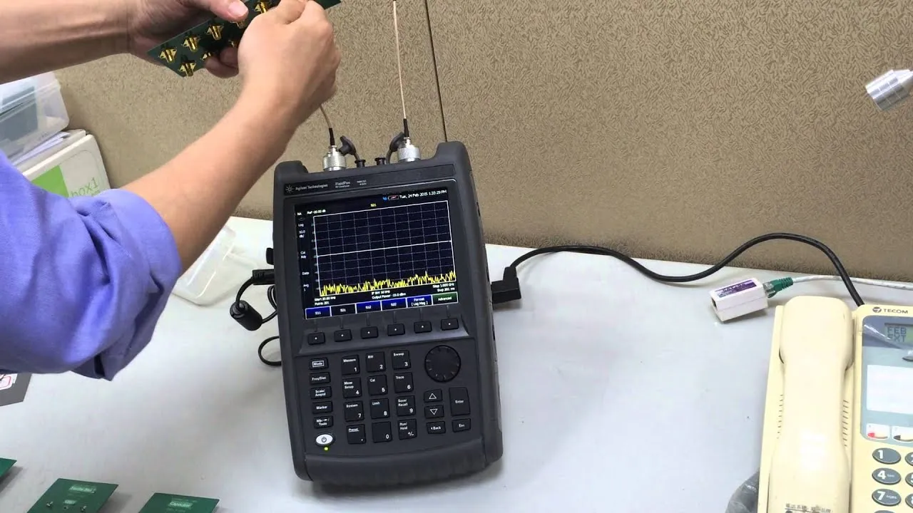
Figure is closely related to the "Connect and verify a 50 Ω BNC termination step by step" section. It translates the textual checklist (e.g., identify impedance, select terminator, hand-tighten, run checks) into a clear visual workflow, serving as an important tool for guiding lab operations and preventing subtle errors.
| Step | Action | Record Field | Note |
|---|---|---|---|
| 1. Identify port impedance | Verify if your scope/generator input is 50 Ω or 1 MΩ. | Port, Z₀ | Many Tektronix/Keysight scopes switchable. |
| 2. Choose terminator or feed-through | Select a TEJTE 50 Ω true terminator or feed-through terminator rated above your signal power. | Type, Rated W | BNC-KF or BNC-JKKK handle 1 W @ 4 GHz. |
| 3. Hand-tighten connection | Align bayonet lugs; no wrench needed. | Torque_note | Over-torque can deform PTFE. |
| 4. Add strain relief or tee if looping | Use a BNC-JKKK cross adapter when distributing a trigger signal. | Topology | Keep all branches 50 Ω. |
| 5. Run continuity + quick S11 check | Verify return loss @ target frequency using VNA or reflection bridge. | RL@freq | Target ≥ 25 dB below 3 GHz. |
In everyday use, engineers often underestimate how much connection repeatability matters. Re-seating a BNC plug just once can change measured VSWR by up to 0.03 dB. To avoid long-term drift, maintain a short log for each instrument port, noting date, terminator type, and frequency test.
For routine work, TEJTE’s nickel-plated brass BNC-JE and BNC-KF connectors provide consistent mechanical grip and low insertion loss (< 0.15 dB @ 1 GHz). When combined with properly rated terminations, they preserve measurement stability across months of use.
For broader setup guidance, the article SMA to BNC Adapter Lab Integration Guide shows how termination practices fit into mixed-connector environments—a valuable reference if your bench mixes SMA and BNC.
Do you need a tee + terminator to loop a signal?
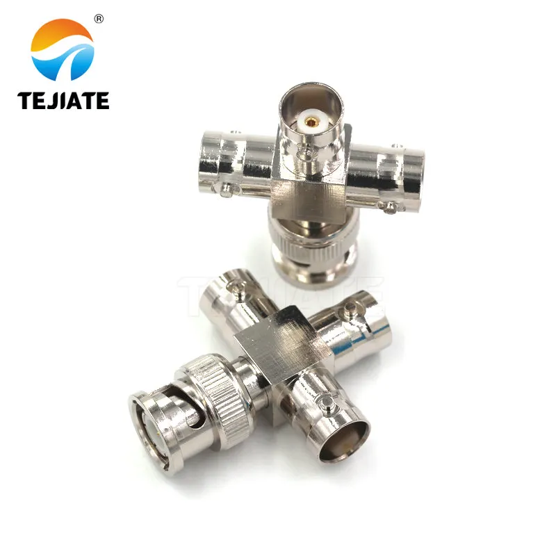
Figure is highlighted in the "Do you need a tee + terminator to loop a signal?" section. It visually presents the key component for solving signal distribution needs. Its feed-through design allows it to provide the correct terminal load for the system while monitoring the signal, making it a fundamental component for building complex test chains.
Sometimes you need to share one source between multiple instruments—a scope and a frequency counter, for example. That’s when a tee + terminator combination makes sense. It lets the signal flow through one path while still maintaining a proper 50 ohm BNC termination at the end of the chain.
Using a bare tee without termination effectively doubles the line impedance, causing reflections that appear as ringing on fast pulses. Instead, attach a feed-through terminator on one branch or use a BNC-JKKK cross adapter rated DC–4 GHz, ensuring that all paths remain balanced.
Here’s a simple checklist for dual-instrument routing:
- Place the terminator at the farthest end of the line.
- Keep tee lengths short—less than 2 cm of exposed path.
- Avoid stacking adapters that increase mechanical stress.
The TEJTE BNC-JKKK adapter’s nickel-plated brass housing and PET insulation keep loss below 0.1 dB @ 1 GHz, ideal for distributing triggers or reference signals between instruments. For higher-isolation setups, a small –3 dB splitter or matching pad performs even better.
What mistakes silently break measurements in lab racks?
The most common lab mistakes aren’t spectacular failures—they’re the quiet, invisible ones:
- Mixing 50 Ω and 75 Ω cables. A single RG59 jumper in a 50 Ω chain adds 1.3:1 VSWR even before connectors.
- Loose barrels and stacked adapters. Every extra joint adds 0.02 dB loss and introduces mechanical play.
- Under-terminating loop-through paths. Without a proper load, return loss drops below 20 dB and edges blur.
- Over-spec power, under-spec return loss. A 2 W terminator with only 15 dB RL still reflects 14 % of your signal.
One practical habit is to label every connector chain. For instance, tag each TEJTE BNC-KF panel port with its impedance and max wattage. If you’re unsure about a connector’s match, the detailed assembly guide on tejte.com/blog/bnc-bulkhead-connector-guide explains how panel mounting affects VSWR and how to prevent strain before termination.
When problems persist, engineers often discover that one connector’s dielectric cracked or oxidized after months of use. A tiny change in pin depth can shift impedance by 2 Ω—enough to invalidate a calibration.
Routine inspection and low-cycle connectors like the BNC-JE male plug (≤ 0.15 dB loss @ 1 GHz) help avoid that surprise.
When should you pick brand-grade terminators over generics?
Not all terminators are created equal. The market is full of low-cost 50 ohm loads, many with unspecified VSWR and thin plating that fades after a few cycles. In a busy lab where ports see hundreds of insertions each month, those small defects add up.
Brand-grade parts like TEJTE BNC-KF and BNC-JKKK use tight-tolerance machining and hard-nickel plating to hold geometry over time. Even after 500 cycles, contact resistance stays below 1 mΩ. By contrast, a generic terminator can creep to 5 mΩ and distort rise times on high-speed edges.
Environmental factors matter too: in humid environments, corrosion and salt spray attack bare brass. TEJTE’s nickel-plated finish and RoHS-compliant design help maintain reliable surface conductivity for network and IoT devices. When you see long-term drift or measurement noise, the connector is often to blame—not the instrument.
Document your terminations so maintenance stays consistent
Good labs treat terminators like calibration standards. Every piece gets a label, date, and cycle count. This small habit saves countless hours of diagnosis later.
Recommended label fields:
- Impedance (50 Ω / 75 Ω)
- Power rating (1 W / 2 W)
- Last inspection date
- Return loss check @ 1 GHz
When terminators are shared across benches, use color tags—blue for 50 Ω, yellow for 75 Ω—to avoid cross-use. A simple Excel log or barcode sheet with each connector’s serial number helps trace drift and replacement history.
The TEJTE BNC-KK adapter’s stable bayonet fit and PTFE dielectric make it a safe choice for frequent plug-in testing and panel distribution. Its consistent fit prevents wear that often occurs with loosely toleranced copies.
Speed up ordering with the Terminator & Pad Matrix
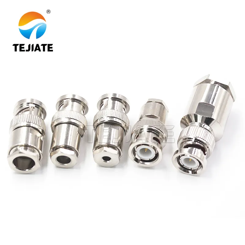
| Impedance | Type | Rated Power | Freq Range | RL Target | Use Case | Connector Gender | Example Model / Notes |
|---|---|---|---|---|---|---|---|
| 50 Ω | True terminator | 1 W | DC – 6 GHz | ≥ 25 dB | Scope / Gen Port | Male / Female | BNC-KF 4-Hole Flange |
| 50 Ω | Feed-through | 1 W | DC – 4 GHz | ≥ 23 dB | Loop-through / Trigger | Male-Female | BNC-JKKK Cross Adapter |
| 75 Ω | True terminator | 0.5 W | DC – 3 GHz | ≥ 22 dB | Video / CCTV | Male | BNC-KK Bulkhead Adapter |
| 50 Ω | Matching Pad | 1 W | DC – 2 GHz | ≥ 25 dB | 50 to 75 Ω Conversion | Male-Female | Custom TEJTE Pad Design |
| 25 Ω | Special Load | 2 W | DC – 1 GHz | ≥ 20 dB | Bias Network / Fixture | Male | Custom Order |
FAQ
1. When would a 25-ohm BNC terminator be used instead of 50 Ω?
Rarely. You’ll find 25-ohm loads in specific bias networks or impedance-bridging fixtures, usually when two 50 Ω ports are paralleled.
For general RF testing, always stick with 50 ohm BNC terminators—that’s the standard for oscilloscopes and signal generators.
If you’re unsure about your system impedance, check TEJTE’s BNC 50 Ohm vs 75 Ohm Impedance Guide for detailed matching examples.
2. Do I still need an external terminator if my oscilloscope has a 50 Ω input mode?
Usually not. Most modern scopes have a built-in 50 Ω termination option that performs like an external load.
However, if your test chain includes loop-through or trigger distribution via a tee adapter, then an external terminator (for example, a TEJTE BNC-JKKK feed-through type) helps maintain correct impedance at the far end of the path.
3. How much power can a small terminator safely dissipate?
Check both the rated wattage and signal type.
A 1 W BNC terminator typically handles up to 20 Vpp continuous or 0.8 W RMS without overheating.
For CW or long-pulse applications, leave 30–40 % headroom.
TEJTE’s BNC-KF and BNC-JKKK models are verified for 1 W @ 4 GHz, offering reliable headroom for bench instruments.
4. Is a feed-through terminator better than a true terminator?
Neither is “better” overall—it depends on your measurement style.
A feed-through terminator (like TEJTE’s BNC-JKKK) lets you measure or loop signals while maintaining a 50 Ω load, whereas a true terminator simply ends the line cleanly.
For one-port measurements or unused outputs, always use a true terminator.
5. Can I loop one generator into two instruments using a tee and a terminator?
Yes, provided you keep all paths 50 Ω.
Use a short BNC tee or cross adapter and terminate the unused port with a 50 Ω load.
For precision timing work, a small matching pad or buffer amplifier provides better isolation than a passive tee.
You can find connection examples in the SMA to BNC Adapter Lab Integration Guide.
6. Will using a 75 Ω terminator on a 50 Ω source damage equipment?
Not directly, but it hurts measurement accuracy.
The mismatch reflects power and distorts amplitude readings—especially above 500 MHz.
Always match impedance through the whole chain or use a 50 to 75 Ω matching pad as described in TEJTE’s RF Coax Cable Guide.
7. Why do my readings change after adding multiple adapters before the terminator?
Each extra joint slightly alters the reference plane and adds tiny insertion loss or capacitance.
Stacking several barrels or elbows can reduce return loss by 1–2 dB.
Whenever possible, use direct TEJTE bulkhead connectors (like BNC-KK or BNC-KF) and retest return loss after every hardware change to maintain calibration accuracy.
Final Note
Bonfon Office Building, Longgang District, Shenzhen City, Guangdong Province, China

A China-based OEM/ODM RF communications supplier
Table of Contents
Owning your OEM/ODM/Private Label for Electronic Devices andComponents is now easier than ever.
