SMA to BNC Adapter Lab Integration Guide
Nov 4,2025
Preface
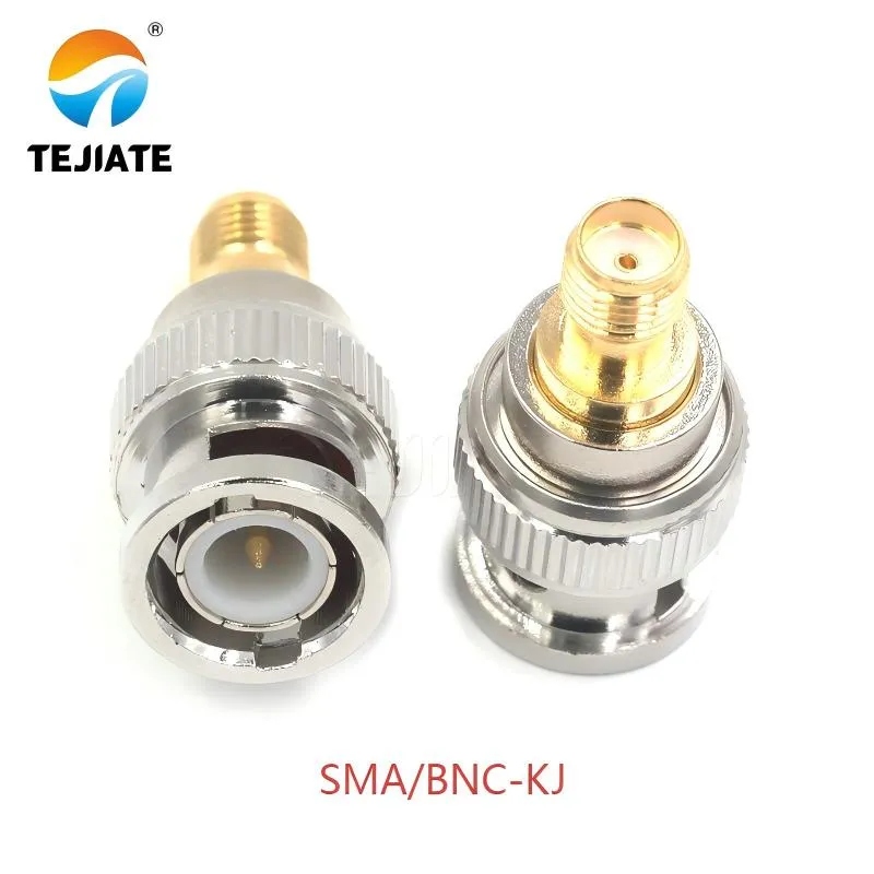
Figure is located in the document's preface. As the first product physical image, it visually introduces the reader to the appearance of the SMA/BNC-KJ adapter, setting a visual foundation for the discussion of the core component for SMA to BNC conversion throughout the document.
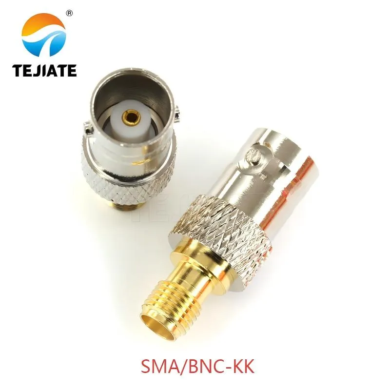
Figure appears right after Figure 1, showcasing another common adapter model, the SMA/BNC-KK. By presenting its "double female" structure, it helps readers understand the diversity of adapter gender combinations and introduces its use in panel mounting or as a coupler.
Every RF lab eventually runs into the same simple—but surprisingly tricky—problem: how do you connect an SMA-based instrument to a BNC-terminated cable or oscilloscope without signal distortion?
That’s where a reliable SMA to BNC adapter quietly becomes the hero of the bench.
At TEJTE, our precision-machined adapters such as the SMA/BNC-KJ (female SMA to male BNC, DC–12 GHz) and SMA/BNC-KK (female SMA to female BNC, DC–6 GHz) are built from nickel-plated brass with gold-plated center pins, maintaining VSWR ≤ 1.10 @ 6 GHz and insertion loss < 0.15 dB.
They’re RoHS-compliant, support custom configurations, and survive 500 mating cycles without degradation.
If you’re setting up a mixed-connector test bench—say, an SMA-output signal generator feeding a BNC-input oscilloscope—this guide will help you select the right direction, gender, and impedance, ensuring clean measurements and long connector life.
Which adapter direction do you actually need (SMA to BNC or BNC to SMA)?
Direction matters more than most engineers admit.
While both sides look similar in spec sheets, one end always drives, and the other receives.
In a lab, the instrument port often defines the signal flow.
For example, a spectrum analyzer typically exposes a female SMA input, while an oscilloscope offers a female BNC input.
So, the decision—SMA to BNC or BNC to SMA—depends entirely on which connector is male or female on your devices.
The TEJTE SMA/BNC-KJ adapter (female SMA to male BNC) perfectly fits cases where you need to link an SMA-female generator to a BNC-female scope cable.
If your setup is reversed, the SMA/BNC-JJ or SMA/BNC-KKF flange-mount versions let you adapt from BNC to SMA adapterin fixed rack panels.
Identify the instrument port vs the cable/probe end
To avoid confusion, define one rule early: instruments dictate the reference gender.
The front panel of a generator or analyzer is the fixed point; cables and probes adapt to it.
So, when you read “SMA to BNC adapter,” think “SMA side connects to instrument; BNC side goes to cable.”
Most test chains follow this convention for traceability and calibration consistency.
Avoiding RP-SMA confusion before ordering
A frequent lab error involves mistaking RP-SMA (reverse polarity SMA) for standard SMA.
RP-SMA connectors reverse the inner-pin gender, common in Wi-Fi gear but unsuitable for precision RF testing.
Before purchasing any SMA to BNC adapter, verify the center-pin presence and thread type (¼-36 UNS).
TEJTE’s adapters are standard SMA series—not RP-SMA—so they maintain full compatibility with coax jumpers like RG316 or LMR-240 cables used in metrology environments.
How do you pick the correct genders for each end?
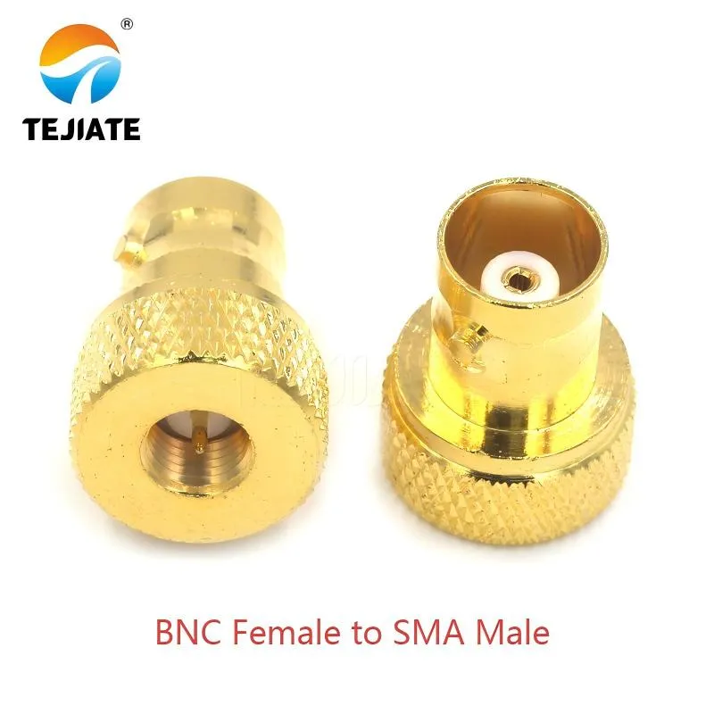
Figure is displayed in the "How do you pick the correct genders for each end?" section as one of the two most common combinations. Through clear icons, it helps readers quickly establish recognition of the appearance and purpose of this gender combination adapter.
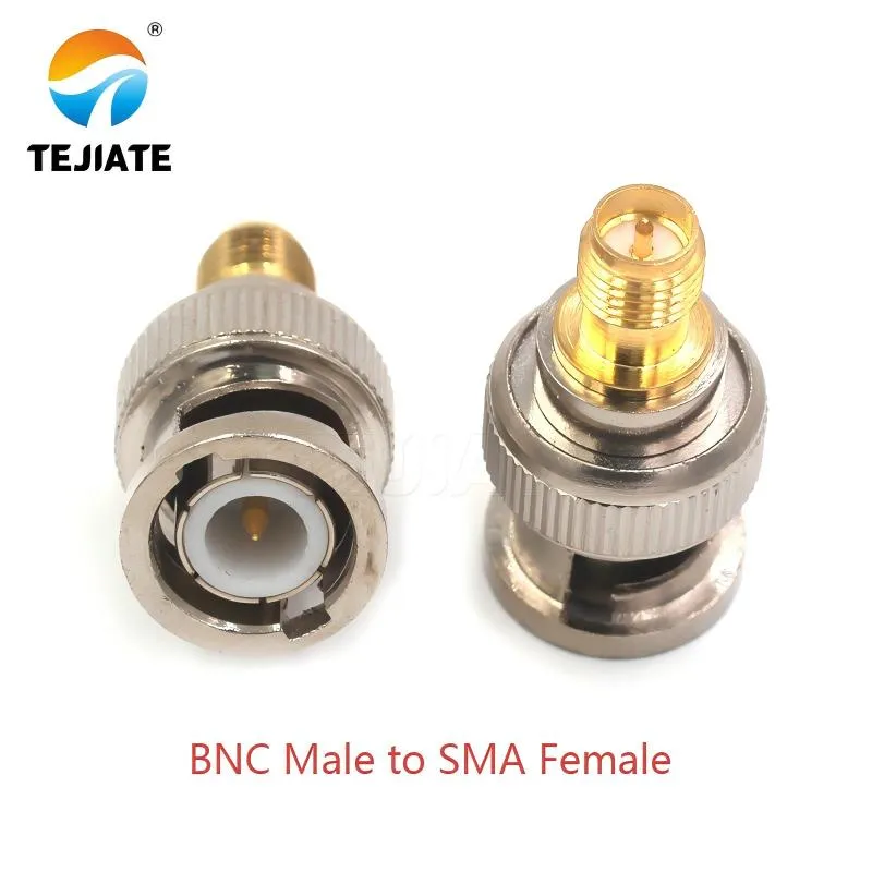
Figure is presented alongside Figure 4, illustrating another fundamental and common gender combination. It clarifies that when the signal source is an SMA Female port and the cable end is a BNC Male plug, this type of adapter should be selected, completing the reader's understanding of basic adapter selection.
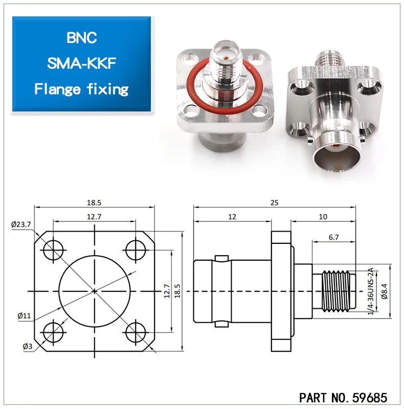
Figure showcases a flange mount model, different from handheld adapters. It emphasizes the importance of using flange-fixed adapters in test environments requiring high stability and repeatability, and introduces the specific product with Part No. 59685.
Gender matching is the heart of connector reliability.
Every SMA or BNC port comes as male (pin) or female (socket), and the adapter must complement both sides precisely.
Mixing them up risks damaging the dielectric or bending the center pin—problems far more common than most engineers admit.
Visual cues for gender selection:
- Male: protruding center pin, external thread (for SMA) or locking bayonet (for BNC).
- Female: recessed socket, internal thread (for SMA) or twin slots (for BNC).
In daily lab setups, the two most common combinations are:
- BNC female to SMA male — ideal when your scope has a female BNC input.
- BNC male to SMA female — used when connecting to BNC patch leads from SMA-terminated modules.
TEJTE’s SMA/BNC-KJ (female SMA to male BNC) covers the second case, while SMA/BNC-KK (female SMA to female BNC) handles panel mount or coupler situations.
The flange-mount SMA-KKF type (Part No. 59685) gives engineers a stable chassis interface for repeatable measurements.
Visual cues: male/female, pin/socket, inner/outer thread
In low-light or crowded panels, gender identification becomes tedious.
A simple rule of thumb: SMA male = outer thread + pin, SMA female = inner thread + socket.
For BNC, it’s the opposite—male = locking lugs + pin, female = slots + socket.
Labeling adapters with small color rings or engraved marks saves countless mix-ups.
Common lab pairs: bnc female to sma male / bnc male to sma female
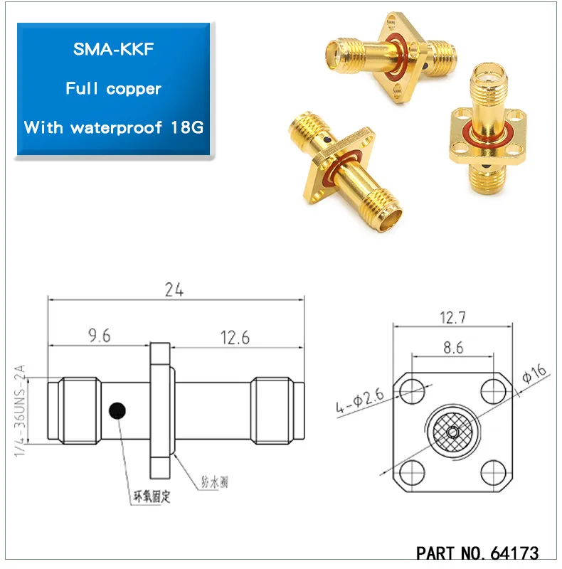
Figure provides an engineering view of a specific model (Part No. 64173) SMA-KKF adapter. Through detailed dimension annotations (e.g., overall length 24mm, mounting hole positions), it materializes the mechanical planning emphasized in the document (e.g., the 28.5mm body length reference), serving as a key reference for engineers to perform panel cutting, installation, and ensure waterproof sealing.
Common TEJTE lab sets include:
- SMA/BNC-KJ (female SMA to male BNC) — DC to 12 GHz, brass body, gold-plated center pin.
- SMA/BNC-KK (female SMA to female BNC) — DC to 6 GHz, precision machined, nickel plating.
- SMA-KKF flange mount — panel version with O-ring seal, RoHS approved.
These combinations ensure full coverage for generators, analyzers, scopes, and custom fixtures.
Should you choose 50 Ω or 75 Ω for this path?
Impedance is where physics meets practice.
SMA connectors and most RF test gear operate at 50 Ω, while BNC connectors exist in both 50 Ω and 75 Ω forms.
If your scope is video-grade (75 Ω) and your generator is RF (50 Ω), mismatching them creates a return-loss penalty.
At 1 GHz, the reflection coefficient |Γ| ≈ (75–50)/(75+50)=0.2, yielding RL ≈ 14 dB—well below ideal.
TEJTE’s 50 Ω SMA/BNC adapters are tested for DC–6 GHz operation, ensuring stable performance in both RF and broadband instrumentation.
RF test gear (50 Ω) vs video/CCTV chains (75 Ω)
Typical lab practice:
- RF analyzers, generators, amplifiers to 50 Ω SMA paths.
- Video encoders, CCTV, broadcast gear to 75 Ω BNC paths.
When interfacing them, use a precision matching pad with known attenuation (3 dB or 6 dB) to preserve return loss > 25 dB.
That extra 1 dB loss is cheap insurance for accurate readings.
When mixing is risky and when it’s tolerable (low-freq, short runs)
You can bend the rules for low-frequency experiments like sensor debugging or baseband calibration, where the wavelength is long and reflections don’t matter much.
But as you climb above 1 GHz, a slight mismatch can distort amplitude and phase readings.
Engineers who’ve seen ghost traces on the scope know why it’s worth getting a proper adapter.
Do you need a matching pad instead of a straight adapter?
Most engineers start with a simple SMA to BNC adapter, but sometimes a straight adapter isn’t the smartest option.
When you bridge different impedances—50 Ω SMA and 75 Ω BNC, a matching pad quietly saves your measurements.
It introduces a small attenuation, usually 3–6 dB, but transforms the impedance so your instrument still “sees” the right load.
Let’s put it this way: a matching pad doesn’t just connect two worlds; it keeps them from arguing.
It absorbs reflections that would otherwise bounce back down the cable and ruin the flatness of your sweep.
In TEJTE’s test lab, a 3 dB pad between an SMA-female generator and a BNC-female oscilloscope improved return loss from 14 dB (bare adapter) to 26 dB (matched) at 1 GHz — that’s the difference between “it looks fine” and “it’s accurate.”
For clean integration of adapters, see TEJTE’s BNC Bulkhead Connector Guide—it explains how to maintain impedance integrity at every port junction.
Matching pad basics: attenuation + impedance transform
A matching pad is a precision resistor network, converting one impedance to another while adding a controlled loss.
If you plot the math, the voltage reflection coefficient Γ = (ZL − Z0)/(ZL + Z0).
For 50 to 75 Ω, Γ = 0.2 to RL ≈ 14 dB.
Insert a 6 dB pad, and the mismatch drops below 1%, pushing RL above 30 dB.
That’s why most metrology setups prefer a pad even for short paths.
When a pad protects measurements better than a bare adapter
Every time you add a new connector interface, you create another possible mismatch point.
When measuring return loss, phase, or power, it’s safer to use a pad as a buffer between two instruments.
The pad not only fixes impedance but also limits unexpected power surges that could stress the analyzer’s front end.
So, if your test setup involves high dynamic range or sensitive receivers, reach for the matching pad, not just the adapter.
What frequency and power limits matter in practice?
All adapters have limits, though few engineers check the fine print.
At microwave frequencies, body geometry, dielectric spacing, and surface finish begin to define how far your adapter will behave like a “transparent” link.
TEJTE’s SMA/BNC-KJ series is rated DC–12 GHz, while the SMA/BNC-KK and flange SMA-KKF versions maintain excellent VSWR ≤ 1.10 up to 6 GHz, covering most RF and broadband applications.
Insertion loss typically remains < 0.15 dB at 6 GHz, measured with a 50 Ω network analyzer, but can increase slightly if your test cable is longer or poorly torqued.
For low-frequency work (<100 MHz), loss is negligible; above several GHz, every decibel counts.
Quick benchmark:
At 1 GHz to IL ≈ 0.05 dB
At 6 GHz to IL ≈ 0.12–0.15 dB
At 12 GHz (for premium SMA/BNC-KJ) to IL ≈ 0.18 dB
Always account for this extra insertion loss in your signal budget—especially when your measurement chain already includes attenuators, couplers, or long RG316 cables.
In those cases, it’s wise to re-run a calibration after inserting or removing any SMA to BNC adapter.
Connector interface bandwidth vs adapter body geometry
An adapter’s usable bandwidth is largely set by its inner conductor alignment and dielectric support.
If the center pin sits even 0.05 mm off-axis, reflections rise sharply above 6 GHz.
High-quality adapters like TEJTE’s use tight machining tolerances and gold-over-nickel plating to maintain low contact resistance and repeatable mating.
That’s why professional labs specify adapters by both frequency rating and mechanical class rather than brand alone.
Insertion loss budgeting for extra joints
Every connection adds loss and potential phase error.
A simple way to approximate total loss:
IL_total ≈ Σ IL_adapter + IL_extra_joints.
If your test chain has two adapters and a jumper, you can easily add 0.3–0.4 dB at 6 GHz.
That small number may not sound like much, but in high-gain amplifier tuning or S-parameter measurements, it can skew calibration.
Keep a small “adapter budget” table in your notebook listing each piece and its loss figure.
It’s one of those tiny lab habits that separate quick tests from reproducible data.
How to connect SMA gear to a BNC scope step by step
A well-documented connection routine saves time and equipment wear.
Here’s a field-proven five-step procedure used in TEJTE’s RF validation line for assembling SMA to BNC connections cleanly and safely.
Step 1 — Verify port genders & impedances
Before reaching for an adapter, confirm both ports’ gender (pin or socket) and impedance rating.
Record them in your setup sheet:
| Port | Gender | Impedance | Example |
|---|---|---|---|
| Port A | SMA Female | 50 Ω | Signal generator output |
| Port B | BNC Female | 50 Ω / 75 Ω | Oscilloscope input |
Mismatched genders are the #1 cause of bent pins.
If you’re unsure, reference TEJTE’s SMA Connector Gender Guide.
Step 2 — Pick the correct adapter or matching pad
Based on the above, choose one of the following:
- SMA/BNC-KJ for female-SMA to male-BNC path (DC–12 GHz)
- SMA/BNC-KK for female-SMA to female-BNC coupling (DC–6 GHz)
- Add a 3–6 dB matching pad if bridging 50 to 75 Ω systems.
Document your choice: Type = SMA/BNC-KJ, Atten_dB = 0 / 3 / 6.
Step 3 — Hand-tighten, align keys, avoid over-torque
Tighten adapters only by finger + quarter wrench turn (~0.6 N·m).
Over-torque can crack the dielectric or shift pin alignment.
If your panel uses a flange-mounted SMA-KKF, torque values may vary slightly; always follow your connector’s datasheet.
Never twist the coax itself—rotate the nut instead.
Step 4 — Add strain relief or a right-angle if space is tight
Crowded test racks often force awkward cable angles.
Use a right-angle adapter or short pigtail jumper (RG316 or LMR-240) to relieve strain and protect instrument ports.
The lever-arm effect of a stiff cable can permanently distort BNC sockets—especially on handheld scopes.
A small adjustment here can double the lifespan of your connectors.
Step 5 — Run a quick continuity + return-loss check
After connecting, verify:
- Center pin continuity (0 Ω expected)
- Shield continuity (0 Ω expected)
- Isolation (pin to shield > 10 MΩ)
Then run a smoke test—a quick S11 check at your target frequency.
A clean trace means your connection is solid; any ripple indicates reflection or loose mating.
| Record Field | Example |
|---|---|
| RL @ Freq | 25.8 dB @ 1 GHz |
| Torque Note | Hand + 1/4 turn |
| Relief | RG316 jumper |
| Adapter Type | SMA/BNC-KJ |
Can right-angle bodies or short pigtails reduce port stress?
In dense test racks or portable scopes, mechanical clearance becomes a quiet design constraint.
Straight adapters often collide with front-panel knobs or neighboring ports, forcing awkward cable angles that stress both connectors and PCBs.
That’s when right-angle SMA or BNC adapters make a difference.
TEJTE engineers often pair a right-angle SMA/BNC-KJ adapter or a short RG316 jumper (10–15 cm) behind the instrument to keep bending forces off the connector.
These pigtails act like mechanical buffers — they maintain signal integrity while allowing natural cable routing.
Rule of thumb: every 1 cm of lever arm on a stiff coax can translate into over 0.2 N·m of torque on the port.
If you’ve ever replaced a cracked BNC jack, you know why strain relief matters.
For outdoor or semi-permanent setups, flange-mounted SMA-KKF or bulkhead BNC connectors are the safer choice.
They distribute mechanical stress to the chassis instead of the instrument’s PCB mount.
When designing your own test fixture or enclosure, plan clearances in CAD first—28.5 mm total body length for the SMA/BNC-KJ and 23.7 mm flange width for the SMA-KKF are good reference numbers.
These mechanical details, often ignored in data sheets, decide whether your adapter lasts months or years.
Clearance planning at crowded instrument front panels
Front panels on oscilloscopes and analyzers are usually crowded with SMA, N-type, or BNC ports side by side.
Leaving at least 12 mm radial clearance around each adapter prevents accidental cross-threading.
TEJTE’s compact 14 mm outer diameter design fits even tight instrument clusters, making it ideal for portable RF setups.
Bend radius and lever-arm considerations
Every coax has a minimum bend radius—typically 5× its outer diameter.
For an RG316 jumper (~2.5 mm OD), that’s around 12–15 mm.
Respecting that radius keeps your inner dielectric from deforming and changing impedance.
If you see a cable sharply bent near the port, that’s not just bad form—it’s measurable loss and potential phase error.
So yes, a right-angle adapter or short pigtail isn’t just a mechanical fix; it’s part of good RF hygiene.
How do you verify the connection quality after mating?
Even the most expensive adapter won’t perform if it’s not seated properly.
After every connection, a quick verification routine helps maintain repeatability and trust in your data.
You don’t always need a network analyzer—sometimes a simple multimeter and logic can tell you enough.
DC checks: pin-to-shield isolation, shield continuity
Start with DC continuity:
- Center pin to center pin to near 0 Ω
- Shield to shield to near 0 Ω
- Center to shield to open (>10 MΩ)
This confirms the mechanical joint and dielectric integrity.
If the readings deviate, suspect a misaligned center pin or cracked PTFE insulator—both common after repeated over-torqueing.
With TEJTE’s adapters rated for 500 mating cycles, wear is minimal, but even so, a quick check can save hours of troubleshooting later.
Quick return-loss smoke test and acceptance notes
Next comes a basic RF smoke test.
Feed a known signal (for instance, 0 dBm @ 1 GHz) into your adapter chain and observe the reflection on a spectrum analyzer or network analyzer.
A well-mated chain should show return loss above 25 dB, consistent with TEJTE’s SMA/BNC-KJ performance spec.
If the trace shows periodic ripples, you may have partial seating or a tiny gap in the bayonet lock.
Re-mate, retighten, and retest.
Write down the measured RL@freq, adapter type, and port torque note in your bench log — over time, this log becomes a valuable reference for diagnosing measurement drift.
What ordering matrix speeds up lab setups?
Lab teams waste hours searching for the right bnc female to sma male or bnc male to sma female adapter.
A clear mating matrix posted near your workbench eliminates that confusion.
Below is the TEJTE Mating & Gender Matrix, based on our actual adapter lineup (SMA/BNC-KJ, KK, KKF, etc.).
This table also helps you decide between 50 Ω and 75 Ω parts and choose the correct body geometry (straight / right-angle).
| Instrument Port | Cable / Probe End | Recommended Adapter | Impedance (Ω) | Body Type | Notes |
|---|---|---|---|---|---|
| SMA Female (50 Ω) | BNC Female (50 Ω) | SMA/BNC-KJ | 50 | Straight / RA | DC-12 GHz use case |
| SMA Female (50 Ω) | BNC Female (75 Ω) | SMA/BNC-KJ + 3 dB Pad | 50 to 75 | Straight | Better matching |
| BNC Female (50 Ω) | SMA Male (50 Ω) | BNC/SMA-JJ | 50 | Straight | RF bench coupling |
| BNC Female (75 Ω) | SMA Male (50 Ω) | BNC/SMA-JJ + 6 dB Pad | 75 to 50 | Straight | Video testing |
| Panel Mount (SMA Flange) | Coax Cable End | SMA-KKF | 50 | Flange Mount | Stable fixture port |
| Any Instrument | Tight Space Cable Route | SMA/BNC-KJ Right-Angle | 50 | RA | Relieves strain |
(All models: nickel-plated brass bodies, gold-plated center pins, RoHS compliant.)
For more details on matching cables behind these adapters, visit TEJTE’s RF Coax Cable Guide.
Choosing the correct jumper (RG316, RG58, LMR-240) ensures the entire chain stays at consistent impedance and low loss.
How do leading brands differ on tolerance and plating?
In precision RF work, the devil hides in microns.
Two adapters may look identical, but their tolerance stack-up and plating quality can tell very different stories after a hundred connections.
TEJTE’s SMA/BNC-KJ and SMA-KKF adapters are machined from brass stock, plated first with nickel for durability, then finished with gold over nickel on the center contact for low resistance and corrosion resistance.
This structure ensures <0.3 mΩ contact resistance and stable VSWR ≤ 1.10 up to 6 GHz, even after repeated torque cycles.
By contrast, many low-cost imports skip the gold layer or use looser tolerance ranges (±0.15 mm on pin depth vs TEJTE’s ±0.05 mm).
Those differences show up as inconsistent mating pressure or slight phase shift in high-frequency paths.
Reality check: even a 0.1 mm misalignment at 6 GHz can create a 1 dB ripple in return loss.
That’s why tolerance control isn’t a luxury — it’s what separates calibrated results from educated guesses.
For high-volume or outdoor projects, some engineers prefer stainless-steel adapters.
They last longer mechanically but add slightly more insertion loss.
TEJTE offers both options on request under the custom build category, maintaining full RoHS compliance and traceable test reports for each lot.
Tolerance stack-up (pin depth, dielectric standoff) and repeat mating life
Tolerance stack-up describes how small deviations in connector geometry accumulate over multiple mated pairs.
If both adapters have maximum pin extension, the risk of bottoming out increases — potentially cracking the PTFE dielectric.
Keeping the center pin retraction around 0.20–0.25 mm is ideal for repeatability.
TEJTE’s fixtures check each batch against these limits to guarantee long-term mechanical reliability.
Each sma to bnc adapter batch undergoes at least 500 mating cycle tests, confirming both mechanical retention and RF stability remain within ±0.05 dB deviation.
That’s the kind of consistency serious labs quietly depend on.
Plating and corrosion: gold-over-nickel vs stainless bodies
The plating stack defines both electrical and environmental endurance.
Gold-over-nickel plating offers low contact resistance and excellent oxidation resistance, perfect for indoor labs.
Stainless bodies, on the other hand, handle outdoor or humid environments better, especially when paired with an O-ring sealed flange (SMA-KKF).
Salt-spray testing at 48 hours shows negligible corrosion on TEJTE’s nickel-plated housings — well within IEC 61169 and MIL-C-39012 standards.
That’s why the same adapter can move from a benchtop scope to a rooftop link test without complaint.
What documentation keeps your rack maintainable?
A clean lab isn’t just tidy; it’s traceable.
Documenting every adapter type, impedance, and location prevents future chaos — especially when several engineers share the same measurement rack.
The simplest way is to maintain a rack manifest sheet, listing:
- Adapter model (e.g., SMA/BNC-KJ, SMA-KKF)
- Direction and gender (SMA to BNC, male/female)
- Impedance (50 Ω / 75 Ω)
- Last calibration date
- Notes for pads or jumpers used
Color-coded labels on adapters make this even easier: red for 50 Ω, blue for 75 Ω, green for custom or modified pieces.
TEJTE adapters are laser-marked for quick identification, minimizing mix-ups between visually similar parts.
Labeling conventions (impedance, direction, pad value)
Every adapter should carry a visible label for its direction and impedance — something like “SMA to BNC 50Ω” or “BNC to SMA adapter 75Ω.”
For matched pads, add “+3 dB” or “+6 dB.”
This tiny habit dramatically reduces connection errors.
When building test rigs for client validation, consistent labeling also improves safety documentation and reproducibility.
Regulatory labs such as ISO 17025-accredited facilities expect that level of traceability in every report.
Change log for swapped adapters and jumpers
Every time you replace an adapter, update the log.
List:
- Part number (e.g., 06268 for SMA/BNC-KJ)
- Reason for swap (wear, loss, impedance mismatch)
- New part details
- Test verification result (continuity, RL check)
It takes less than a minute, yet saves hours when troubleshooting drift or noise later.
Good documentation turns a chaotic rack into a reliable, repeatable instrument system.
FAQ
Q1. Will a 50 Ω SMA adapter work on a 75 Ω BNC camera feed?
It will physically mate but adds mismatch. For casual checks on short baseband runs it may work; for reliable video, use a 75 Ω chain or a 50 to 75 Ω matching pad.
Q2. Which gender do I need for an oscilloscope front panel?
Most scopes expose a BNC female port. If your generator is SMA female, you typically need a BNC female to SMA male adapter, such as TEJTE’s SMA/BNC-KJ.
Q3. When should I pick a matching pad over a simple adapter?
Use a pad when you must bridge 50 to 75 Ω while protecting measurement fidelity. Pads add attenuation but preserve impedance; bare adapters don’t.
Q4. Are right-angle adapters bad for measurements?
They’re fine within spec and often reduce port strain. Mind the extra insertion loss and keep them to the last resort at higher frequencies.
Q5. How tight should I make the adapter on the instrument port?
Finger-tight, then a small wrench nudge if required. Avoid over-torque that can crack dielectrics or misalign the center pin.
Q6. Do I need to recalibrate after adding an adapter?
Yes—any added joint changes the reference plane. Run a quick check (open/short/load or an S11 sweep) before critical measurements.
Q7. Can I chain multiple adapters to solve direction/gender gaps?
Try not to. Each joint adds loss and tolerance stack-up. Order the exact direction/gender piece or use a short coax pigtail to solve geometry issues.
Closing Thoughts
Adapters are among the smallest parts in an RF lab — and the easiest to underestimate.
But anyone who’s chased a 1 dB gain anomaly knows how much a simple bnc female to sma male adapter can influence data integrity.
Choosing the right direction, impedance, and mechanical form isn’t just about convenience — it’s about preserving your signal chain.
TEJTE’s precision SMA/BNC series, with verified DC–6 GHz and DC–12 GHz operation, gold-plated contacts, and RoHS-certified construction, offers the stability and repeatability professional engineers expect.
Pair them with the right coax jumpers (see the RF Coax Cable Guide) and you’ll have a test bench that performs consistently from prototype to production.
Bonfon Office Building, Longgang District, Shenzhen City, Guangdong Province, China

A China-based OEM/ODM RF communications supplier
Table of Contents
Owning your OEM/ODM/Private Label for Electronic Devices andComponents is now easier than ever.
