
A router antenna that works well on a test bench may disappoint once the equipment is installed behind a metal cabinet or at the far end of a warehouse. Replacing it with a higher-gain model sounds like an easy fix. Sometimes it works. Sometimes the dead zone simply moves somewhere else.
The problem is rarely the gain rating alone. A suitable WiFi antenna must cover the radio’s operating frequencies, direct energy toward the intended coverage area, and fit the physical installation. Cable length and connector compatibility matter too, particularly when the antenna sits away from the wireless device.
Before comparing product listings, start with the radio specifications and the location where the signal needs to reach. Those two details will eliminate many unsuitable options before price becomes a factor.
Which WiFi Frequency Bands Must Your Antenna Support?
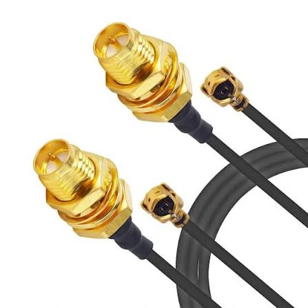
WiFi antenna coaxial cable assembly featuring gold-plated RF connectors, black coaxial cables, and bulkhead mounting interfaces. Suitable for wireless communication equipment, antenna installations, and custom RF cable applications.
Start with the frequency range, not the product name. A listing that says “wireless antenna” or “dual band” does not tell you everything needed for a purchasing decision.
Most WiFi equipment operates in the 2.4 GHz and 5 GHz bands. Newer devices supporting Wi-Fi 6E or Wi-Fi 7 may also use 6 GHz, depending on the hardware and regional requirements. An antenna specified for 2.4 and 5 GHz should not be assumed to cover 6 GHz as well.
The distinction matters when replacing an antenna on an existing router or wireless module. A connector may fit perfectly while the antenna itself is unsuitable for the intended band. The device can still power on, and the connection may even appear to work, but that does not establish that the antenna is operating within its specified range.
Check the radio manufacturer’s documentation first. Then compare the antenna datasheet against the frequencies the device actually uses.
| WiFi application | What to verify before ordering | Potential mismatch |
| 2.4 GHz wireless device | Specified operating range covers the required channels | Antenna intended for a different band |
| Dual-band router | Both 2.4 GHz and 5 GHz are supported | Product covers only one of the two bands |
| 6 GHz-capable access point | Datasheet explicitly includes the required 6 GHz range | Assuming a dual-band model also supports 6 GHz |
| Embedded WiFi module | Radio specifications, antenna port, and matching requirements | Connector fits, but the RF design is incompatible |
Frequency coverage is only the first check. If the device operates near the edge of an antenna’s specified range, ask for its VSWR or return-loss data across the relevant band. A single headline specification cannot describe the antenna’s behavior at every operating channel.
There is another detail worth checking when sourcing replacement parts: some suppliers group WiFi, cellular, GPS, and other wireless antennas under similar product categories. These products may look alike, particularly when they use short coaxial leads and compact connectors. Their intended frequency ranges can be very different.
If your application involves several wireless technologies, identify the radio being connected to each antenna port instead of treating all external antennas as interchangeable. TEJTE’s WiFi antenna guide provides additional context on distinguishing WiFi antennas from other wireless antenna applications.
When Does a Higher-Gain WiFi Antenna Actually Help?
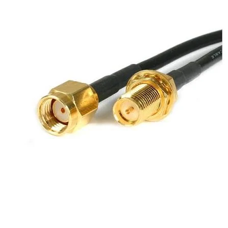
Close-up view of gold-plated SMA coaxial cable connectors showing the connector contact, threaded coupling structure, and bulkhead mounting design. Used in WiFi antenna systems, RF equipment, and wireless communication applications.
Consider two installations. In the first, a router serves devices scattered across one large workshop. In the second, it serves devices on several floors. The same high-gain antenna may suit the first installation better than the second.
The reason is the radiation pattern.
Antenna gain, measured in dBi, describes how energy is concentrated in a particular direction relative to an ideal isotropic reference. It does not mean the antenna creates additional transmitter power. With many omnidirectional antenna designs, higher gain produces a flatter radiation pattern, concentrating more energy around the horizontal plane.
That can be useful when devices are spread across one floor. It may be less helpful when equipment sits directly above or below the antenna.
The following comparison is a useful starting point, although the actual radiation pattern depends on the antenna design and installation.
| Installation requirement | Antenna to evaluate | Main consideration |
| Devices distributed around a router | Omnidirectional WiFi antenna | Coverage around the antenna, subject to its actual pattern |
| Wireless link between two known locations | Directional WiFi antenna | Beam direction and alignment |
| Equipment across multiple floors | Antenna with suitable vertical coverage | Higher gain may narrow the vertical beam |
| Radio installed inside a metal cabinet | External antenna mounted outside the enclosure, where appropriate | Metal can obstruct or alter the RF pattern |
An omnidirectional WiFi antenna is not equally effective in every direction. Its pattern can contain weaker areas, and nearby metal, the router enclosure, and the mounting surface can change the installed result. Moving an antenna a short distance away from a large metal surface may help more than changing its gain rating.
Directional antennas present a different trade-off. They concentrate energy toward a selected direction, making them worth evaluating for fixed links between buildings or other installations with a known target. However, alignment becomes part of the job. A directional model aimed incorrectly can perform worse than an omnidirectional alternative.
What Should You Check Before Replacing the Existing Antenna?
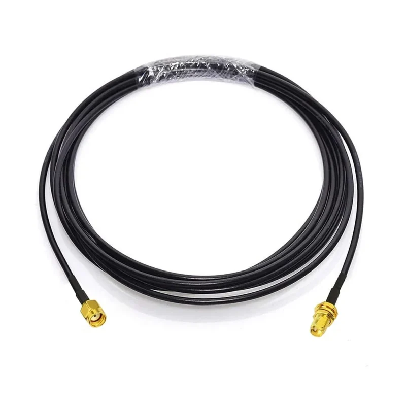
Do a simple site check before purchasing a replacement. Record where the wireless device sits, where the connection becomes weak, and whether the antenna can be repositioned without adding a long cable.
For a home router, that may mean moving the antenna away from a wall or avoiding an enclosed shelf. In an industrial installation, it may mean mounting the antenna outside a metal housing and checking whether the cable route introduces additional loss.
One practical point is often missed during purchasing: the antenna used for evaluation should be installed in a way that resembles the final product. A short cable on an open bench is not equivalent to a longer cable routed through an enclosure. If the installation changes, the RF result can change too.
For a repeatable procurement specification, record these items before comparing suppliers:
- Required frequency bands and supported channels.
- Antenna gain and radiation pattern, where available.
- Mounting position and antenna orientation.
- Cable type and finished cable length.
- Connector interface at both ends.
- Environmental requirements, including outdoor exposure if applicable.
The selection sequence is straightforward: confirm frequency compatibility, define the coverage area, compare gain and radiation patterns, and then account for mounting and feed-cable constraints. Once these details are settled, connector selection becomes much easier—and less likely to produce a replacement part that fits physically but fails to meet the actual application requirements.
Why Does an SMA Antenna Sometimes Fail to Fit a WiFi Router?
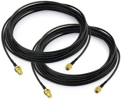
Two coiled black SMA RF coaxial cable assemblies featuring gold-plated connectors. Suitable for WiFi antenna extensions, wireless communication equipment, RF modules, and custom coaxial cable installations.
A replacement antenna arrives, the thread looks right, and the buyer expects a straightforward installation. Then the center contacts turn out to be different. This is an avoidable mistake, but it happens because SMA and RP-SMA connectors look remarkably similar in product photos.
The difference is in the center contact, not just the threaded outer shell. A standard SMA male connector normally has a center pin. An RP-SMA male connector has a center socket. Their mating female interfaces have the corresponding opposite arrangements. Reversing the polarity changes the contact configuration, even though the outside dimensions may appear similar.
If you are sourcing an external WiFi antenna, check the router manual or inspect the original antenna and equipment port. Do not identify the interface from thread size alone. Product titles can also be misleading when a seller uses “male” or “female” without clearly specifying standard or reverse polarity.
The cable matters just as much. A WiFi antenna extension cable has two connector ends, and both need to match the intended equipment and antenna. For a custom cable assembly, write down each end separately. For instance, specify the equipment-side interface, antenna-side interface, cable length, and any required adapters. This is more useful than asking a supplier for an “SMA extension cable” and hoping the supplied configuration is correct.
One more specification deserves attention: impedance. Most conventional WiFi antenna connections use a 50-ohm RF path. An antenna or cable intended for a different impedance should not be substituted simply because the connectors mate. The mismatch can affect return loss and VSWR, even when a basic continuity check passes.
For repeat purchasing, keep the connector family and polarity in the bill of materials. If a supplier proposes an alternative, request confirmation of the mating interface and relevant RF specifications before approving the substitution.
How Much Loss Can a WiFi Antenna Extension Cable Add?
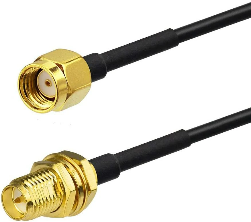
Close-up product view of SMA coaxial cable connectors featuring gold-plated metal bodies, threaded coupling interfaces, and black coaxial cables. Designed for RF signal transmission, WiFi antenna connections, and customized cable assemblies.
An extension cable can solve a real installation problem. Moving an antenna outside a metal enclosure, for example, may be more useful than leaving it beside the radio electronics. The trade-off is that every additional length of coaxial cable introduces attenuation.
The amount depends on the cable construction, operating frequency, and finished length. A cable that works adequately for a short 2.4 GHz connection may be less attractive for a longer run at 5 GHz or 6 GHz. Check the attenuation specification at the actual operating frequency rather than comparing cables by diameter or appearance alone.
Suppose the selected cable has a specified attenuation of 0.5 dB/m at the frequency being used. A 2-meter run would contribute approximately 1 dB of cable loss. That figure excludes connector and adapter losses, so the complete assembly may introduce additional attenuation. The value is illustrative; use the actual cable datasheet for a purchasing decision.
A longer cable is not automatically a bad choice. The question is whether the installation benefit justifies the added loss. A short extension that allows an antenna to clear a metal panel may improve the practical result. An unnecessarily long cable, on the other hand, adds loss without necessarily improving coverage.
| Installation situation | What to compare | Practical concern |
| Short connection inside a device | Cable flexibility and connector dimensions | Tight routing can put stress on the termination |
| Antenna mounted outside an enclosure | Attenuation at the operating frequency and total length | Added cable loss may reduce the expected benefit |
| Long cable run to a remote antenna | Lower-loss cable options and installation space | Thicker cable may be harder to route |
| Outdoor installation | Jacket suitability, sealing, and mechanical support | Moisture ingress or strain can damage the assembly |
Cable diameter also affects sourcing. A connector designed for a particular coaxial cable may not accept another cable with a different outer diameter or construction. The center conductor, dielectric, braid, and ferrule must work together as a termination system. Substituting a cable based on appearance alone can lead to poor assembly quality or inconsistent RF results.
For a longer run, compare the attenuation figures for the complete frequency range of interest. TEJTE’s RG coaxial cable guide provides additional background on cable construction and loss. The useful comparison is the specified attenuation at your operating frequency and required length, not simply whether the cable is described as flexible or low loss.
What Should a Supplier Check Before Shipping a WiFi Antenna Cable?
A cable assembly can look correct and still fail an RF test. The connector may be the right family, the cable may have the correct color, and the finished length may match the order. None of those observations establishes that the assembly meets its electrical requirements.
Start with the physical details. Check the center contacts, threads, connector body, cable entry, and any visible damage around the termination. For crimped assemblies, the connector must be compatible with the cable dimensions and the specified termination method. A connector intended for one cable family should not be substituted for another just because both can be inserted into the same equipment port.
The installation deserves a separate check. A cable bent sharply against an enclosure, pulled sideways at the connector, or routed under a cover may behave differently from the approved sample. Follow the cable manufacturer’s minimum bend radius and provide enough slack to avoid loading the connector mechanically.
Electrical verification should reflect the intended application. A continuity test can detect an open conductor or an unintended short circuit, but it cannot establish that an RF assembly has acceptable insertion loss or impedance matching. Where the application requires defined RF limits, specify the relevant tests and frequency range.
For example, insertion-loss testing evaluates signal loss through the assembly, while VSWR or return-loss measurements help assess impedance matching. The acceptance limits should come from the project requirements or approved product specification; they should not be invented after the samples arrive.
This last point becomes important when an order moves from sampling to production. A supplier might use a different cable, alter the connector termination, or change the finished length to accommodate a new installation. Such a change may look minor on the assembly bench, but it changes the approved configuration.
If an alternative component is proposed, request the revised specification and verify it against the original requirements. For critical applications, test the revised assembly before releasing the change to production.
The goal is not to request the most expensive cable or the highest-rated connector. It is to buy an assembly that fits the equipment, meets the required RF limits, and can be reproduced consistently. A clear specification gives both the buyer and supplier a common reference before the order reaches the production line.
What Should You Check Before Approving a WiFi Antenna Order?
A supplier sends a replacement antenna that looks almost identical to the approved sample. The connector fits, the cable is black, and the product carries the same advertised gain. It seems reasonable to accept the shipment.
Then the assembly reaches production. The cable is shorter than the original, the mounting base sits differently against the enclosure, and the installer has to reroute the wire. None of these differences was obvious in the quotation.
For a WiFi antenna purchase, appearance is a poor substitute for a specification. Before approving an order, compare the delivered configuration with the part that was actually tested.
Start with the details that affect installation: connector interface, cable length, mounting dimensions, and the required frequency range. If the antenna is part of a custom assembly, check the drawing revision too. A supplier may have changed a component without changing the general product description.
The same check applies to repeat orders. A part approved six months ago should not be treated as interchangeable with a new version simply because the model name has not changed.
How Do You Compare WiFi Antenna Quotes Without Missing Hidden Differences?
Ask two suppliers to quote the same specification before comparing prices. Otherwise, the numbers can be misleading.
One quotation might cover an antenna with a fixed cable. Another might cover the antenna alone. A third could include an adapter that the first supplier does not provide. The cheapest offer may become the more expensive option once the missing components are added.
Confirm the operating frequency range and gain specification. If the antenna will connect through an extension cable, ask for attenuation data at the intended frequency. If the installation is outdoors, establish whether the mounting arrangement and environmental protection meet the actual requirements.
A proposed alternative deserves the same scrutiny. Suppose a supplier offers a different coaxial cable because the original is unavailable. The substitute might be electrically acceptable but too thick for the existing cable entry. Or it might fit the enclosure while introducing more attenuation than the approved assembly.
Neither issue can be settled by comparing product photographs.
For purchasing teams, a useful practice is to record the approved part number, drawing revision, cable configuration, and any agreed substitutions. When the next quotation arrives, those records provide a reference for checking what has changed.
Which Details Belong in Your WiFi Antenna BOM?
A BOM entry should be useful to someone who did not participate in the original supplier discussion.
For example, writing “external WiFi antenna, 5 dBi” leaves several questions open. The operating bands are unspecified, the connector polarity is missing, and there is no indication of whether a cable is included.
These fields are examples, not a universal checklist. A compact antenna installed directly on a router may not need a separate cable specification. A remote antenna connected to an industrial controller probably does.
Be explicit about what can change. If the cable length has a permitted range, document it. If the connector must remain exactly as approved, do not leave that decision to the supplier.
When Should You Test the Complete Antenna Assembly?
Consider an antenna mounted outside a metal enclosure. The prototype passes its initial checks, but the production team later routes the cable through a narrow opening and around an internal bracket. The connector now experiences side loading, and the cable follows a tighter bend.
That is no longer quite the same installation that was approved.
Before releasing a production order, fit the sample into the intended equipment whenever practical. Check the mounting clearance, connector engagement, cable route, and the cable manufacturer’s minimum bend radius. For an outdoor installation, inspect the mounting and sealing arrangement against the expected exposure conditions.
RF testing should follow the requirements of the project. Continuity testing can identify an open conductor or an unintended short circuit, but it cannot confirm that the antenna assembly meets a specified VSWR or insertion-loss limit.
If the project requires RF measurements, define the test frequency range and acceptance limits before ordering. Keep the results with the approved sample or assembly revision. If the supplier later changes the cable, connector, or antenna model, review the change before relying on the original test results.
This does not mean every inexpensive replacement antenna needs an elaborate qualification program. The amount of testing should reflect the consequences of a failure and the requirements of the finished product.
FAQ
Will a higher-gain WiFi antenna always improve coverage?
No. If a weak signal occurs in a particular room or behind a metal enclosure, check the installation before assuming that more gain is the answer.
Can an SMA antenna replace an RP-SMA antenna?
Not automatically. The center-contact arrangements differ, even though the threaded interfaces may look similar. Confirm the equipment port and the antenna connector before ordering. An adapter may be an option, but it introduces another connection and needs to be checked for mechanical fit and RF suitability.
Do I need a test report for a replacement antenna?
That depends on the application. A routine replacement may need only a fit check and basic inspection.
Can one antenna work with both 2.4 GHz and 5 GHz WiFi?
Some antennas cover both bands. Check the specified frequency range before using one antenna for a dual-band router. A model rated only for 2.4 GHz should not be treated as a dual-band replacement.