
An SMP connector can fit into its mating interface and still be unsuitable for the finished RF assembly.
Consider two microwave modules connected through a floating bullet adapter. The first prototype works on an open bench, where the boards are carefully aligned by hand. Once installed inside the enclosure, however, the connection becomes intermittent. The PCB spacing has shifted slightly, the bullet no longer sits within its intended engagement range, and the RF response changes when the housing is tightened.
The connector itself may not be defective. The problem is often an incomplete mating specification.
Unlike threaded SMA interfaces, SMP connectors are frequently selected for blind-mate assemblies where the mating parts cannot be manually aligned during installation. Their compact push-on interface makes them useful for modular RF equipment, but successful integration depends on more than impedance and operating frequency.
Before approving an SMP design, engineers need to identify the mating components, retention geometry, available board spacing, and mechanical movement permitted by the complete assembly.
Which RF Assembly Requires an SMP Interface?
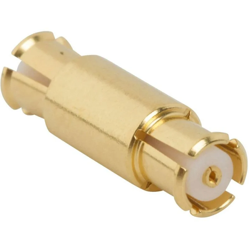
The first selection question is not which SMP connector has the highest frequency rating. It is which components must connect, how they are mounted, and what movement occurs during assembly.
An SMP RF connector can serve several different mechanical arrangements. A PCB-mounted receptacle may connect directly to a compatible mating interface, while a board-to-board system commonly uses two receptacles joined by an intermediate bullet. Cable-mounted versions introduce another set of requirements involving coaxial cable dimensions, termination methods, and strain relief.
These arrangements may share a similar front interface, but they are not interchangeable assemblies.
Identify the Fixed Interfaces Before Selecting the Mating Part
Start by identifying which side of the connection is mechanically fixed.
In a stacked PCB assembly, both receptacles may be soldered to their respective boards. The bullet provides the intermediate connection and, when the approved design permits, accommodates some assembly variation.
The exact receptacle geometry matters. SMP plug and receptacle descriptions can be confusing because catalog terminology sometimes refers to the center contact while other descriptions emphasize the outer mating structure. Buyers should use the manufacturer’s interface drawing rather than relying entirely on male or female labels.
A purchasing request that says only “50-ohm SMP connector” leaves several critical decisions unresolved.
The supplier still needs to know whether the application requires a PCB receptacle, cable plug, floating bullet, or complete matched interconnect system.
Separate Board-to-Board Links From Cable-to-Board Connections
Board-to-board and cable-to-board connections create different mechanical problems.
For a board-to-board SMP connection, the principal concerns include PCB separation, receptacle mounting height, bullet engagement, and accumulated positioning tolerances. The connector must accommodate the intended assembly sequence without forcing the boards into an incorrect position.
A cable-to-board connection adds cable routing and termination stress. Even when the SMP mating interface is compatible, a stiff coaxial cable can apply lateral force to the PCB receptacle. That load may affect contact alignment or solder-joint durability.
For cable-specific installation considerations, see TEJTE’s SMP cable routing and module connections.
The following comparison helps separate the initial mechanical requirements before detailed part selection.
A configuration that works in a laboratory fixture may behave differently after the boards are secured inside a production enclosure. Mechanical qualification should therefore reflect the final assembly, not only an isolated connector pair.
Define the Mechanical and RF Constraints at the System Level
Before requesting samples, establish the operating conditions of the entire connection.
The mechanical drawing should identify nominal board spacing, spacing tolerance, connector mounting heights, available installation clearance, and expected alignment error. The RF specification should define impedance, operating frequency range, acceptable VSWR or return loss, and insertion-loss limits.
Most SMP applications use a nominal 50-ohm interface, but the actual frequency capability depends on the specific connector design and complete mating arrangement. A manufacturer’s maximum series rating should not be treated as a guaranteed rating for every PCB transition or cable assembly.
These requirements should be recorded before the supplier selects a bullet or retention style.
How Does an SMP Blind-Mate Connection Handle Misalignment?
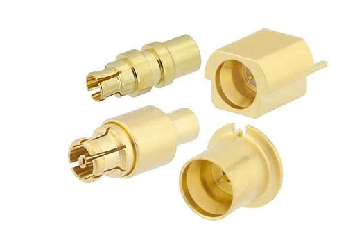
Different SMP connector configurations used in PCB-mounted, cable-mounted and board-to-board RF assemblies. Selection depends on mating geometry, mounting method and mechanical requirements.
Blind mating allows two RF interfaces to connect during module insertion or board assembly without direct manual access to the mating point.
It does not mean the connection can tolerate unlimited positioning error.
An SMP blind mate connector system must be designed around the movement permitted by its receptacles, bullet geometry, and surrounding mechanical structure.
Distinguish Blind Mating From Manual Connector Alignment
With a threaded SMA connection, the operator normally aligns the interfaces before tightening the coupling nut. A blind-mate SMP assembly may be engaged when a PCB or RF module slides into its final position.
The mating components must therefore enter the connection within their approved alignment limits.
A floating bullet can provide mechanical compliance in a compatible design, but its movement is constrained by the mating geometry. If the module approaches at excessive offset or angle, the bullet may contact the receptacle incorrectly.
Forcing the assembly closed can damage contact surfaces or produce an unstable RF connection.
Evaluate Axial and Radial Misalignment Separately
Two alignment conditions require separate evaluation.
Axial misalignment occurs along the connector mating direction. In a board-to-board assembly, it is commonly associated with variation in board spacing, connector height, and mechanical stack-up.
Radial misalignment occurs perpendicular to the mating axis. It can result from PCB hole-position tolerances, connector placement variation, mounting features, or enclosure alignment.
Angular misalignment may introduce additional loading and must be considered where the mating-system specification identifies it.
An assembly can meet its axial engagement requirement while exceeding the allowable radial offset. The reverse is also possible.
Check the Bullet and Receptacle Geometry as a Matched System
The bullet and both receptacles must be evaluated together.
A bullet that appears to fit two SMP interfaces may still be inappropriate for the required retention configuration or board spacing. Different receptacle engagement geometries can change the force needed for mating and separation.
This is particularly relevant when a design combines fixed retention on one side with controlled movement on the other.
Before approving the combination, request the manufacturer’s mating compatibility information and dimensional drawings for all three components.
Confirm Misalignment Limits From the Exact Assembly Drawing
There is no single axial or radial misalignment allowance that applies to every SMP connector assembly.
The permissible values depend on the actual receptacle pair, bullet design, engagement depth, and operating conditions.
During prototype evaluation, engineers should check both the nominal position and the expected worst-case assembly positions. Where RF performance is critical, these conditions should also be included in network-analyzer testing.
A connection that mates successfully is only the first indication of compatibility. Mechanical clearance, contact engagement, and RF behavior must all remain acceptable within the approved tolerance range.
Which Retention Style Fits the Required Mating Cycle?
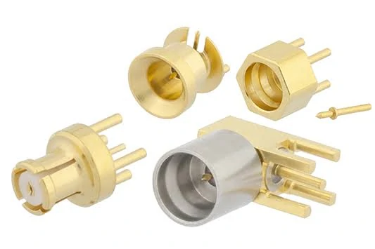
SMP blind-mate connector and receptacle configurations designed for compact RF modules and PCB assemblies where mating occurs without direct manual alignment.
Retention style is easy to overlook because two SMP interfaces can look nearly identical from the outside. Mechanically, however, full-detent, limited-detent, and smooth-bore configurations can behave very differently during assembly and removal.
The correct choice depends on where the connection needs holding force, where movement must remain possible, and how often the module will be serviced.
Evaluate Full-Detent Interfaces for Higher Retention Requirements
A full-detent interface is generally used where stronger mechanical retention is required after mating.
That does not mean it should automatically be specified on both sides of a floating bullet.
In a blind-mate board-to-board system, excessive retention at both interfaces can make assembly difficult and increase the force transferred into the PCB, solder joints, or module housing during removal. The correct configuration should follow the approved mating arrangement for the specific receptacles and bullet.
For procurement, “SMP full detent” should therefore be treated as a mechanical requirement rather than a quality grade.
Evaluate Limited-Detent and Smooth-Bore Interfaces
Limited-detent designs provide a different balance between retention and release. They may suit assemblies where controlled holding force is required without the stronger engagement associated with a full-detent interface.
Smooth-bore configurations reduce mechanical retention further and are commonly relevant where the floating section of the assembly needs greater freedom during mating and separation.
The practical mistake is treating these names as universally interchangeable categories. Actual mating force, unmating force, and compatibility depend on the exact parts.
Before approving production, record the receptacle part number, bullet part number, retention configuration, and specified mating-cycle requirement.
For repeated-service modules, sample testing should include actual insertion and extraction from the finished housing. A connector that feels acceptable when handled individually may behave differently after PCB tolerances and enclosure friction are added.
How Should You Specify an SMP Bullet for Board Spacing?
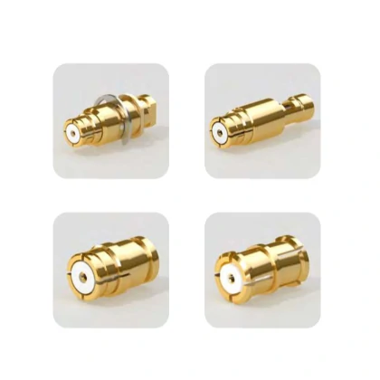
Examples of SMP connector interface configurations used when selecting full-detent, limited-detent or smooth-bore mating arrangements for RF assemblies.
One of the more common SMP sourcing mistakes is selecting the bullet length from the PCB-to-PCB distance alone.
That dimension is useful, but it is not enough.
Measure the Actual Distance Between the Mating Reference Planes
The relevant mechanical stack includes the PCB spacing, receptacle mounting height, engagement depth, PCB thickness where applicable, and manufacturing tolerances.
If the nominal distance between the boards is 10 mm, that does not automatically mean a 10 mm bullet is required.
The bullet connects between mating reference locations inside the two receptacles. Those locations may sit above the PCB surfaces, and the amount of engagement available at each end must remain within the approved operating range.
Check Bullet Length Against the Approved Stack-Up
Tolerance accumulation matters more than the nominal dimension.
Suppose the enclosure, PCB mounting hardware, connector placement, and receptacle height each contribute a small variation. The final spacing at the RF interface may differ noticeably from the drawing’s nominal PCB distance.
The engineering check should therefore compare both minimum and maximum assembled spacing against the valid bullet engagement range.
A bullet that is too long can bottom out or transfer unwanted compressive force into the receptacles. A bullet that is too short may not achieve sufficient engagement.
Neither failure may be obvious from a continuity test.
Which SMP Mounting Style Matches the PCB or Cable?
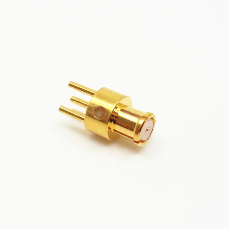
The SMP front interface does not determine how the rear of the connector integrates into the assembly.
That distinction becomes important when procurement teams substitute visually similar parts.
Select PCB-Mount SMP From the Board Footprint
For an SMP PCB connector, check more than connector height.
The board layout needs the correct signal pad, ground arrangement, mounting geometry, and transition into the RF transmission line. At microwave frequencies, the PCB launch can become a significant part of the measured response.
Changing the connector while keeping the same footprint is not automatically safe.
Pin diameter, dielectric position, grounding geometry, and body seating can alter the transition even when the connector physically fits.
The production drawing should therefore lock the connector part number and PCB footprint together.
Evaluate Cable-Mount SMP as a Complete Termination
A cable-mounted SMP connector adds another group of variables: cable outer diameter, dielectric diameter, center conductor construction, shield contact, ferrule dimensions, and termination method.
The cable must also be routed without forcing the connector sideways after mating.
A smaller cable may simplify routing in a compact module, but the cable’s attenuation and mechanical durability still need to meet the application requirement.
For sourcing purposes, do not request only an “SMP cable connector.” Specify the actual coaxial cable family and, where possible, the exact cable construction.
How Do You Confirm SMP RF Performance at Microwave Frequencies?
Mechanical mating does not prove microwave performance.
A complete SMP path may include two receptacles, a bullet, PCB transitions, transmission-line sections, or a cable termination. Every transition contributes to the measured result.
Verify the Rated Frequency of the Complete Mating Pair
Do not apply the highest published SMP series frequency to every connector combination.
Actual usable frequency depends on the specific connector design, bullet, PCB launch, cable termination, and assembly geometry.
A procurement drawing should therefore state the required operating band and ask the supplier to confirm the exact part combination against that band.
Check VSWR, Return Loss, and Insertion Loss Across the Operating Band
S11 is useful for identifying impedance discontinuities and excessive reflection. S21 shows how much signal is transmitted through the assembled RF path.
Both should be evaluated across the actual operating frequency range rather than at one convenient frequency point.
A production assembly may pass continuity while still showing poor return loss because of an incorrect PCB transition, damaged contact, incomplete bullet engagement, or excessive mechanical offset.
When Should You Choose SMP Instead of SMA or SMPM?
SMP is not automatically the better interface simply because the assembly is compact or operates at microwave frequencies.
The mechanical architecture should drive the decision.
Keep SMA Where Threaded Service Access Is Required
SMA remains practical when the connector is accessible to an operator and the application benefits from threaded retention.
External test ports, instrument connections, antenna interfaces, and serviceable cable assemblies often favor SMA because the connection can be manually aligned and tightened.
That mechanical behavior is very different from an SMP blind-mate system.
Using SMP only to save space can introduce unnecessary complexity if the assembly does not actually need push-on mating, floating alignment, or modular board installation.
Choose SMP When Blind Mating and Modular Assembly Dominate
SMP becomes more attractive when boards or RF modules must mate as they are installed into an enclosure.
Typical examples include stacked RF boards, replaceable microwave modules, dense internal RF links, and assemblies where there is no room to rotate a coupling nut.
The advantage comes from the mechanical architecture rather than from the connector name alone.
Evaluate SMPM When the Available Interface Space Is Smaller
An SMPM connector provides a smaller interface for designs where SMP occupies too much space.
That does not make SMPM a drop-in replacement.
The interface dimensions, receptacles, bullets, PCB footprints, and mating hardware must be designed specifically for SMPM. If a project is already built around SMP, changing to SMPM normally requires mechanical and RF redesign rather than a simple component substitution.
A practical selection rule is:
| Design condition | Interface direction | Procurement check |
| Accessible threaded RF port | Consider SMA | Confirm mating/unmating force |
| Blind-mate PCB or module assembly | Consider SMP | Verify approved bullet pairing |
| Blind-mate assembly with tighter space limits | Evaluate SMPM | Confirm assembly retention elsewhere |
| Existing qualified interface | Avoid changing without requalification | Lock complete mating combination |
How Can You Qualify an SMP Blind-Mate Assembly?
A datasheet comparison is not enough for production approval.
For a board-to-board system, qualification should combine mechanical stack-up, mating compatibility, and RF acceptance.
SMP Blind-Mate Qualification Matrix
The following matrix can be used during design review or supplier approval.
| Verification field | Engineering input | Supplier data | Approval rule |
| Interface configuration | Receptacle / bullet / cable | Exact part numbers | Approved mating system |
| Retention style | Full / limited / smooth bore | Mating combination | Match design |
| Board spacing | Nominal + tolerance | Bullet working range | Within engagement range |
| Radial misalignment | Worst-case offset | Allowed radial offset | Within limit |
| Axial variation | Worst-case stack-up | Allowed axial range | Within limit |
| Mating cycles | Required cycles | Rated cycles | Requirement met |
| Frequency | Operating band | Rated band | Fully covered |
| VSWR | Project limit | Test or datasheet result | Pass |
| Insertion loss | Project limit | Test result | Pass |
| Documentation | Drawing / test method | Approved revision | Released |
This table is most useful before the purchase order is released. Once different connector and bullet revisions enter production, tracing a failure back to the original approved combination becomes much harder.
Calculate Radial Misalignment From X and Y Offset
A positive number alone should not be treated as sufficient approval. The project may require additional safety margin for production variation, vibration, or repeated mating.
Axial qualification should be checked separately against the actual bullet engagement range.
The value of this approach is consistency. Procurement, engineering, and the supplier are working from the same acceptance logic instead of separate assumptions.
How Should Buyers Specify an SMP Connector RFQ?
A useful RFQ should describe the complete mating system.
That leaves too many variables open.
For a board-to-board assembly, identify both receptacles and the compatible bullet. Include nominal board spacing, spacing tolerance, retention style, expected mating cycles, operating frequency, PCB footprint, and mechanical alignment requirements.
RF acceptance should also be stated at the intended operating band.
After first-article approval, lock the connector part numbers, bullet part number, PCB footprint, drawing revision, inspection method, and approved material configuration.
A “compatible replacement” should not be accepted solely because the new part mates physically.
FAQ
Can different SMP detent styles use the same bullet?
Not automatically. Compatibility depends on the receptacle geometry, retention design, and manufacturer’s approved mating combination. Verify the exact receptacle and bullet part numbers.
Does an SMP blind-mate connector compensate for any PCB misalignment?
No. Blind-mate assemblies can accommodate only the axial, radial, or angular movement allowed by their specific design.
Can an SMP cable connector replace a board-to-board bullet?
Not directly. A cable assembly introduces bend radius, routing, strain relief, and cable termination requirements that a floating board-to-board bullet does not have.
What should be locked after first-article approval?
Record the receptacle and bullet part numbers, retention configuration, board spacing, PCB footprints, permitted misalignment, operating frequency, RF limits, drawing revision, and inspection method.