
A connector change often starts with a surprisingly simple request: “Can we use SMB here instead of SMA?”
On a purchasing sheet, that may look reasonable. Both are RF coaxial connector families. Both can be found in cable-mount and PCB-mount versions. Depending on the exact part, either may appear in a 50-ohm RF system.
The trouble starts when the drawing reaches production.
An SMA cable arrives for a board that was designed around SMB. The impedance is correct, the cable itself is correct, and electrically the assembly may look perfectly ordinary. It still cannot mate with the port. Adding an adapter fixes the immediate connection problem, but now the enclosure clearance changes, the port carries more mechanical load, and another RF transition has been added.
That is why an SMA vs SMB comparison should begin with the actual RF path, not a catalog specification table.
The useful question is not “Which connector is better?” It is “Which interface creates fewer problems in this particular design?”
Which RF Design Constraint Should Decide Between SMA and SMB?
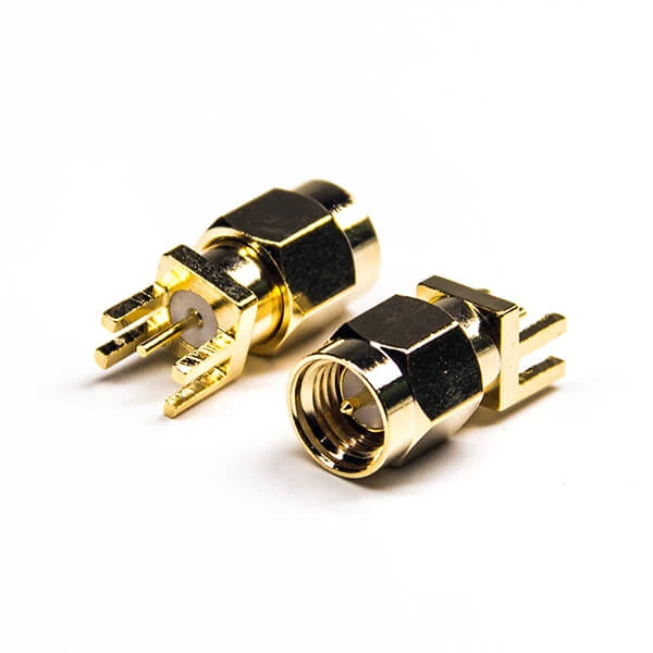
Gold-plated SMA PCB connectors used in RF modules, communication equipment, antenna systems, and board-level coaxial connections.
Start with whatever cannot be changed.
If the equipment already has an SMA port, that fact usually matters more than connector size, assembly speed, or unit price. The same applies to SMB. Existing test equipment, antenna ports, PCB layouts, enclosure holes, and cable assemblies can lock a project into one interface long before procurement begins comparing alternatives.
New designs are different. There, engineers can weigh mechanical access, RF requirements, maintenance, cable routing, and production assembly before the PCB and enclosure are frozen.
That distinction sounds obvious, but it prevents a common sourcing mistake: comparing connector families as though every project starts from a blank sheet.
Start With the Fixed Equipment Interface and Signal Path
A better way to review the design is to follow the signal from one end to the other.
Take a compact radio module as an example. The board may use an SMB connector internally, while the outside of the enclosure presents an SMA antenna port. Between them sits a short coaxial cable assembly.
In that case, “SMA or SMB?” is the wrong question. The assembly may require both.
The board end is determined by the module. The panel end is determined by the external antenna interface. The cable must then be selected around length, routing space, connector termination, and operating frequency.
This becomes more important as frequency rises. A cable can pass continuity testing and still perform poorly in the finished RF path. A bad crimp, damaged dielectric, loose braid termination, or a cable bent too tightly near the connector may not show up on a multimeter.
Mechanical fit can also fail quietly.
A connector may look correct in a supplier photo yet use a rear body intended for a different cable diameter. An RG316 connector should not be assumed to fit RG58 merely because the front interface is SMA. The ferrule, dielectric support, center contact, and cable entry dimensions are part of the connector design too.
For procurement, it helps to write down the complete path before requesting a quote:
- Equipment-side interface
- Cable-side interface
- Impedance
- Operating frequency
- Cable type and length
- Straight or right-angle exit
- PCB, panel, or cable mounting
- Expected mating frequency
That information is far more useful to a supplier than simply writing “SMA cable” or “SMB connector” on the BOM.
Separate Interface Selection From Connector Replacement
A new RF design gives you room to compare.
A replacement usually does not.
Suppose an existing product uses an SMB PCB connector and the supplier proposes an SMA version because it is easier to source. Even if both parts are 50 ohms and cover the required frequency range, the change affects the mating cable, PCB footprint, assembly clearance, and possibly the enclosure.
It is no longer a component substitution. It is a mechanical redesign.
The reverse problem happens too. A buyer may see a smaller snap-on SMB connector and assume it can replace SMA wherever space is tight. Sometimes it can be evaluated for a new design. That does not mean it is a drop-in replacement for an SMA interface already in production.
This is also where adapter use needs some restraint. An adapter is practical when two fixed interfaces must be connected. It should not become the automatic answer to every mismatch. Extra transitions occupy space, add another mating point, and may make a small equipment port carry more weight than intended.
Rank the Constraints Before Looking at Price
Price is easier to compare than mechanical risk, so it often gets discussed first.
That order is backwards.
Not every factor has equal weight.
A production test fixture may care heavily about repeated mating. A sealed communication unit may be connected once and left untouched for years. A dense PCB may be limited by connector height or cable exit direction before RF performance becomes the deciding factor.
This is why a universal “SMA is better” or “SMB is better” answer is rarely useful.
How Does Threaded SMA Coupling Compare With Snap-On SMB?
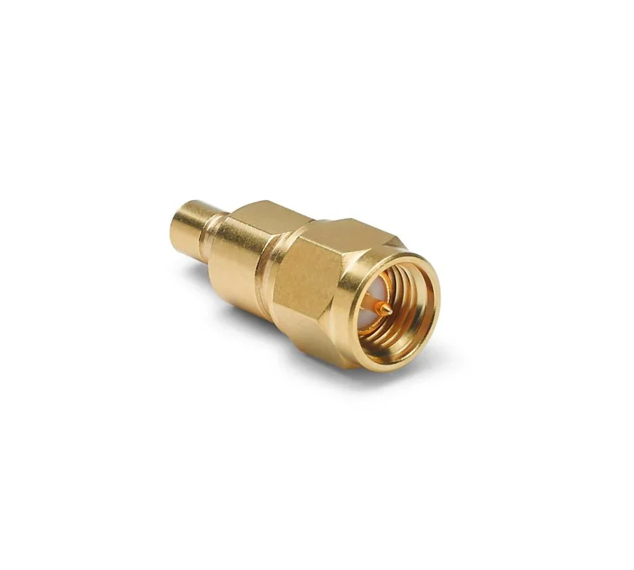
The coupling method changes the way the connector behaves on the assembly line and later in service.
SMA uses a threaded connection. SMB uses a snap-on mechanism.
That sounds like a small mechanical difference. In practice, it affects access, installation speed, retention, tooling, and the way technicians handle the cable.
SMA Needs Room to Be Tightened
An SMA connector has to be threaded onto its mating interface.
That gives the assembler a controlled mechanical connection, but the coupling nut needs space to rotate. On a crowded panel, two nearby connectors can make tool access awkward. A cable exiting at the wrong angle can make it worse.
There is another detail that is easy to miss during manual assembly: tightening force.
For general equipment, operators sometimes install SMA connectors by feel. On test equipment or more sensitive RF connections, controlled torque may be required by the connector or instrument manufacturer. More force is not automatically better. Overtightening can damage mating surfaces and shorten interface life.
This matters during purchasing because the drawing may specify an SMA interface while saying nothing about service access. The connector fits on paper, then becomes difficult to install after the enclosure is built.
SMB Trades Threading for Faster Mating
SMB approaches the same problem differently.
Instead of rotating a nut, the connector is pushed into the mating interface until the snap-on retention structure engages. That can make assembly quicker and may work well in compact internal equipment where threaded access is inconvenient.
But “snap-on” should not be read as “maintenance-free” or “unlimited mating.”
Repeated connection still wears the contact and retention structure. Pulling on the cable instead of the connector body can also stress the termination. In a tight enclosure, enough axial room is still needed to connect and disconnect the part without bending the coax sharply.
So the mechanical choice is less about which connector looks stronger.
For SMA, check thread access, torque practice, and cable movement after installation.
For SMB, check retention force, removal access, mating-cycle requirements, and how the operator will actually disconnect it.
That is the kind of comparison that prevents a connector decision from becoming a production problem later.
Which Connector Fits a Space-Constrained PCB Layout?
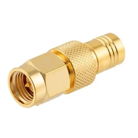
Compact SMB to SMA coaxial adapter used to connect equipment with different RF interfaces while maintaining a practical RF signal path.
A smaller-looking connector does not automatically solve a space problem.
Engineers sometimes compare SMA and SMB by body diameter alone. That misses the space needed around the connector after installation. The mating cable, coupling method, bend radius, nearby components, and enclosure wall can take more room than the connector itself.
A layout can look fine in CAD and still become difficult to assemble.
Compare the Mating Envelope, Not Just the Connector Body
For SMA, clearance is needed around the threaded coupling area. The assembler must be able to align the plug, engage the threads, and rotate the coupling nut without hitting another connector or enclosure feature.
SMB needs a different type of space. The connector is pushed on axially, so there must be enough room in front of the interface for mating and removal.
That difference matters in dense RF hardware.
Consider two connectors placed close together on the same PCB edge. SMA may require more side access for tightening. SMB may reduce that problem, but if the cable exits directly toward another component, the assembly can still become awkward.
The dimensional drawing should therefore be checked in the fully mated condition.
That is the real installation envelope.
Straight and Right-Angle Versions Solve Different Problems
Right-angle connectors are often selected because enclosure height is limited.
They can help, but they move the problem sideways.
A right-angle SMA or SMB cable connector needs enough room for the cable to leave the body without being forced into a sharp bend. If the cable is pressed against a housing immediately after the connector, the coax may carry continuous mechanical stress.
That can damage the termination long before the connector itself fails.
Straight versions may be easier to terminate and inspect, but they require more depth behind the interface.
For PCB layouts, compare both configurations before fixing the board outline.
This catches problems that a connector footprint alone will not show.
Check PCB Grounding and Mechanical Support
The RF interface is only one part of a board-mounted connector.
The PCB footprint controls how the connector is grounded and how mechanical force is transferred into the board.
A connector that is repeatedly mated can put stress into solder joints. That is especially relevant when a stiff cable is attached directly to the PCB connector.
For production designs, review:
- Ground pad arrangement
- Through-hole or surface-mount structure
- Mechanical support tabs
- Connector alignment
- Solder joint accessibility
- Distance from board edge
- Cable load after mating
If the external cable is heavy or frequently moved, the board connector should not be expected to act as a strain-relief device.
The enclosure may need to carry part of that load.
How Should Frequency and Impedance Influence the Choice?
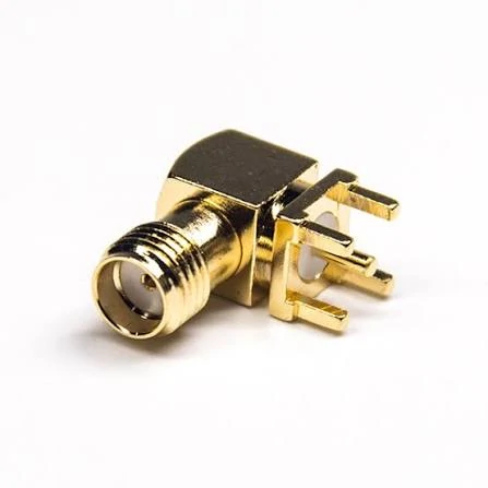
Right-angle SMA board connector designed for RF PCB applications where enclosure height, cable routing, and installation space are limited.
Connector family names are useful for identification. They are not enough to approve RF performance.
“SMA” does not automatically mean a specific maximum frequency. “SMB” does not either.
The exact part number matters.
Compare Rated Frequency Using the Exact Connector
One SMA connector may be intended for general RF use. Another may be designed for substantially higher-frequency operation.
The same problem appears with SMB products. Different body geometry, dielectric structure, manufacturing tolerance, plating, and termination method can change performance.
That may be true for one product series and wrong for another.
If the system operates at 2.4 GHz, the connector should be checked at that band. If it operates near 6 GHz, verify the actual connector and cable assembly there rather than assuming that a catalog family name is enough.
Impedance Can Eliminate a Candidate Immediately
SMA is commonly used in 50-ohm RF systems.
SMB is available in both 50-ohm and 75-ohm forms, depending on product series and application.
This is not a minor specification difference.
A mechanically mating connector with the wrong impedance can introduce reflection and degrade the RF path.
For procurement, impedance should be written explicitly in the BOM rather than left to supplier interpretation.
Do Not Approve the Assembly From Connector Frequency Alone
This is another common trap.
The connector may have enough frequency margin, while the complete assembly does not.
The cable introduces attenuation. Termination quality affects mismatch. Extra adapters create additional transitions. Tight bends can change the cable geometry locally.
For that reason, the RF path should be reviewed as a system.
| Check item | Why it matters |
| Connector rating | Confirms interface capability |
| Cable type | Controls attenuation and flexibility |
| Cable length | Adds frequency-dependent loss |
| Termination | Poor assembly can increase mismatch |
| Adapter count | Adds RF transitions |
| Bend routing | Can stress cable geometry |
| Final VNA test | Shows the behavior of the finished path |
A continuity test confirms that the center conductor is connected.
It does not tell you whether the assembly has acceptable return loss at the operating frequency.
That distinction becomes more important near the upper end of the system band.
When Does Cable Termination Favor SMA or SMB?
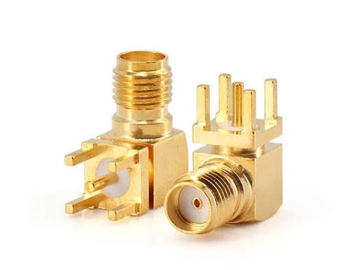
Gold-plated SMA right-angle PCB connectors suitable for RF modules, communication equipment, antenna interfaces, and compact board designs.
For cable assemblies, the front interface often gets most of the attention.
The rear body causes many of the real production problems.
Match the Rear Body to the Actual Coax
A connector for RG174, RG316, RG58, or another cable family needs to match the cable dimensions it will actually receive.
The important dimensions include more than outside diameter.
The connector may depend on:
- Center conductor size
- Dielectric diameter
- Shield or braid structure
- Jacket diameter
- Ferrule dimensions
- Center-pin termination method
A connector can sometimes be forced onto a cable that is “close enough.”
That does not make the assembly correct.
If the ferrule is oversized, the braid may not be compressed properly. If it is too small, the cable can be damaged during crimping. A poorly matched center contact can create an intermittent connection or change the RF transition.
This is why cable designation should always be included in the RFQ.
Compare Cable Exit Before Choosing the Connector Style
The connector may fit the cable but still be wrong for the enclosure.
Straight cable connectors are simple where there is enough depth. Right-angle versions are useful when the cable needs to turn immediately after the interface.
Neither should be selected from appearance alone.
A right-angle connector adds its own internal RF transition and may be more sensitive to assembly quality. A straight connector may force a cable bend too close to the rear body if the enclosure is shallow.
The correct choice is the one that allows the cable to leave the connector naturally.
Factory Assembly Usually Gives Better Repeatability
For low-volume repair work, field termination may be acceptable if the correct tools and inspection procedures are available.
For production quantities, factory-terminated cable assemblies are usually easier to control.
The supplier can standardize:
- Strip length
- Soldering or crimping process
- Ferrule position
- Center contact depth
- Pull-force inspection
- Continuity test
- RF sampling or VNA verification
That repeatability matters more than saving a few seconds during final equipment assembly.
A sample can look perfect and still hide a production risk if the termination process has not been controlled.
For both SMA and SMB cable assemblies, the purchasing question should therefore move beyond connector family.
Those three details often tell you more about production reliability than the connector name alone.
How Do SMA and SMB Behave During Repeated Mating?
Repeated mating is where small mechanical differences start to matter.
A connector used once inside a finished product lives a very different life from one installed on a production test fixture. The second may be connected and disconnected hundreds of times, sometimes by different operators and under less-than-ideal handling.
Look at the Actual Mating Cycle Requirement
It is tempting to assume that SMB is automatically better for frequent connection because it is snap-on, or that SMA lasts longer because it is threaded.
Neither assumption is safe.
Mating-cycle ratings are product-specific. Contact design, plating thickness, manufacturing tolerance, operator handling, contamination, and applied force all affect service life.
For SMA, wear often appears around the threads, center contact, and mating surfaces. Cross-threading or repeated overtightening can shorten life quickly.
For SMB, attention shifts toward the snap retention structure and center contact. If the connector starts to feel unusually loose after repeated use, that is not just a mechanical inconvenience. A changing mating condition can also affect RF repeatability.
Test fixtures deserve more attention here than permanent installations.
That means inspecting it before obvious failure appears.
Watch Cable Movement, Not Only Connector Wear
The connector may still be mechanically sound while the cable termination has started to fail.
Repeated bending close to the rear body can loosen braid contact, damage the dielectric, or fatigue the center conductor. This is common when operators disconnect the cable by pulling on the coax instead of the connector body.
For test cables and production fixtures, add strain relief and define how the cable should be handled.
Visual inspection alone is not enough for sensitive RF work. A cable that looks normal may show a changed return-loss trace during a VNA sweep.
When Is an SMB-to-SMA Adapter a Practical Solution?
Adapters make sense when both interfaces are already fixed.
A test instrument may have an SMA port while the device under test uses SMB. Changing either product is unnecessary, so an SMB-to-SMA adapter provides a straightforward bridge.
That is the good use case.
Problems begin when adapters are used to compensate for poor interface planning.
Verify Both Ends Before Ordering
“SMB to SMA” is still incomplete as a purchasing description.
You need to specify the mating configuration on each side, along with impedance and required operating frequency.
Also check the mechanical arrangement. A rigid adapter attached directly to a small PCB connector can create a long lever arm. Add a cable after that and the board-side port may carry more stress than expected.
In cramped equipment, a short flexible adapter cable can sometimes be easier to manage than a rigid adapter stack.
The RF penalty should also be considered. Every added interface creates another transition. In many systems the added loss is acceptable, but it should not be assumed to be zero.
For measurement setups or higher-frequency paths, test the complete adapter arrangement rather than judging it from individual connector ratings.
How Can You Build an SMA vs SMB Engineering Decision Matrix?
A useful comparison should eliminate bad candidates before cost is discussed.
The following matrix works well during engineering review or supplier approval.
| Engineering factor | SMA | SMB | Approval question |
| Coupling | Threaded | Snap-on | Which mating method fits assembly and service? |
| Impedance | Commonly 50Ω | 50Ω and 75Ω versions exist | Does it match the system? |
| Frequency | Part-specific | Part-specific | Does the exact model cover the operating band? |
| PCB mounting | Available | Available | Does the footprint and clearance fit? |
| Cable mounting | Available | Available | Is the rear body matched to the cable? |
| Retention | Threaded engagement | Snap retention | Is it suitable for vibration and cable load? |
| Maintenance | Tool/access may matter | Quick push-on connection | How often will it be serviced? |
| Cross-mating | Not directly compatible | Not directly compatible | Is an adapter or custom cable required? |
How Should Buyers Specify SMA or SMB Connectors for Production?
Production orders need more detail than sample requests.
A buyer who writes only “SMA male” leaves too much room for interpretation.
A better BOM description should include the interface family, gender, impedance, mounting type, cable or PCB requirement, operating frequency, and any inspection requirement.
For a cable version, include the actual coax type. For a PCB version, provide the footprint or drawing.
The exact material and plating requirements should come from the project specification, not from a generic template.
Before approving a family change from SMA to SMB, or the reverse, check three things with production samples:
- Mechanical fit in the real enclosure
- Cable routing and assembly access
- RF performance across the required band
A bench sample installed in open space can hide problems that appear after the cable is bent into the final product.
FAQ
Can SMB directly replace SMA?
No. They use different mating interfaces. Even if impedance and frequency requirements are similar, they are not directly cross-mateable.
Is SMB always smaller than SMA?
Not in every useful installation sense. Compare the complete mated envelope, including cable exit and removal space.
Is SMA better for high-frequency RF?
Many SMA products are used at higher frequencies, but the exact rating depends on the part number. The connector family name alone is not enough.
Can I use an SMB-to-SMA adapter for testing?
Yes, if the mating configuration, impedance, frequency, and mechanical load are acceptable. For sensitive measurements, verify the complete path.
Which connector is better for repeated mating?
There is no universal winner. Use the rated mating cycles and actual service conditions of the specific connector.