
How can you avoid ordering the wrong SMB to SMA adapter?
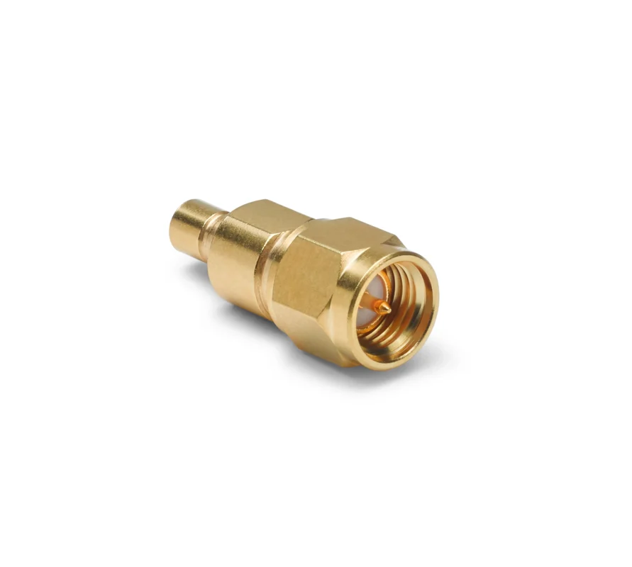
A connector can physically mate and still be the wrong RF component.
This happens often when an engineer replaces a damaged transition part or a procurement team sources a new adapter from a short description such as “SMB-SMA adapter”. The product arrives, the SMB side snaps into place, the SMA cable threads correctly, and the first bench test appears normal.
The issue usually appears later.
The adapter may have the wrong gender combination, an unexpected impedance configuration, insufficient mechanical support, or RF characteristics that change when the cable is routed inside the final enclosure. A transition between SMB and SMA is not only a connector conversion. It creates a new mechanical interface and a new RF discontinuity inside the signal path.
For engineers working with test equipment, wireless modules, GPS receivers, communication devices, and RF assemblies, the selection process should start with the actual equipment interface rather than the adapter name.
An SMB to SMA adapter normally connects an SMB snap-on interface with an SMA threaded interface. The SMB side provides compact installation and quick mating, while the SMA side provides a more secure threaded connection for RF cables and test equipment. The two connector systems solve different mechanical problems, which is why the transition design requires more attention than a simple plug conversion.
Before approving a part number, confirm:
- SMB interface type
- SMA interface type
- Center contact configuration
- 50-ohm requirement
- Operating frequency range
- Adapter body style
- Cable weight and mechanical load
- Required inspection criteria
A reliable RF transition starts with correct identification.
Which SMB/SMA gender pair actually matches your ports?
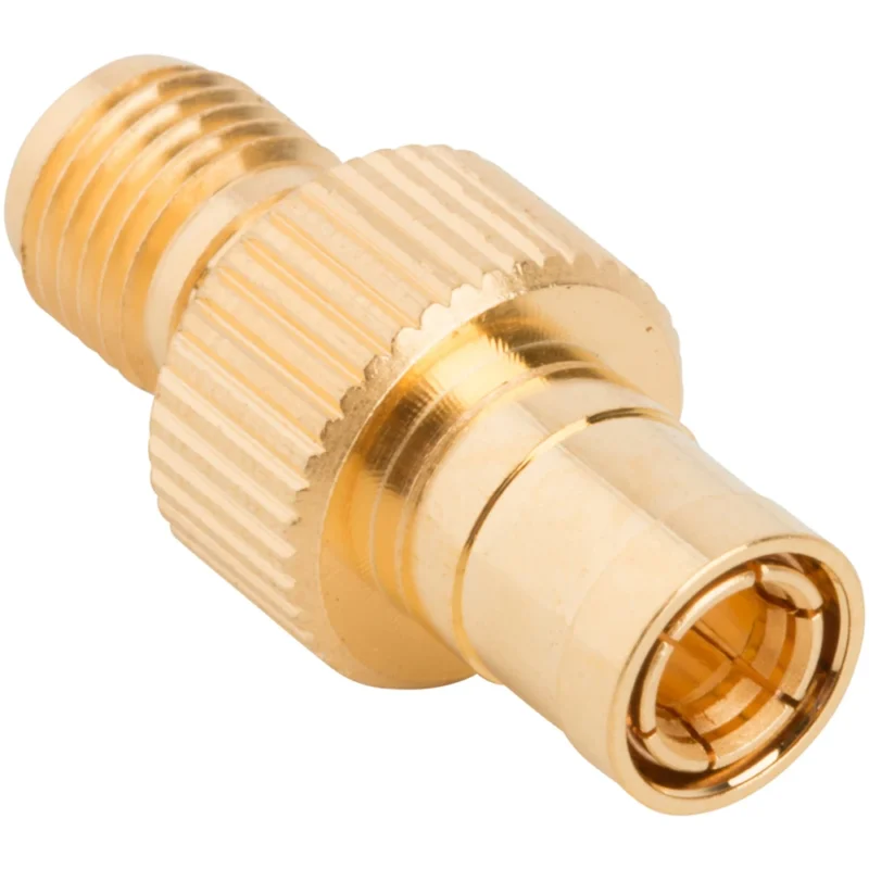
The most common sourcing mistake with SMB to SMA adapters is selecting the gender combination from the product title only.
Different suppliers may describe SMB interfaces differently. Some use “male/female”, while others describe the interface as “plug/jack”. For SMB connectors, the mechanical snap connection and the center contact arrangement both need confirmation.
The correct method is to inspect the mating port on the actual equipment.
Decode the SMB side from the mating contact, not the product photo
For the SMB interface, confirm:
- SMB plug or SMB jack
- Center pin or socket
- Snap-on mating structure
- Cable-mounted, PCB-mounted, or panel-mounted connection
- Original equipment drawing if available
- Actual connector photograph
A product image can be misleading because SMB connectors are compact and the external shell does not always reveal the internal contact configuration.
A better sourcing record should include the equipment-side information before searching for an adapter.
For example:
Equipment port: SMB jack, socket contact, PCB mounted Required transition: SMB plug to SMA female
This description gives the supplier enough information to avoid a visually similar but mechanically incorrect replacement.
Read the SMA end independently from the SMB end
The SMA side requires its own verification.
Confirm:
- SMA male or SMA female
- Internal thread or external thread
- Center pin or socket
- Standard SMA or reverse polarity version
- Cable or equipment mating side
The SMA interface is commonly used with coaxial cables because the threaded coupling provides stable mechanical retention. However, the adapter must match the cable end exactly.
A common mistake is assuming:
SMA male cable → any SMA female adapter
The SMA side may look correct while the internal contact geometry, polarity, or frequency specification differs.
Why is SMB male to SMA female adapter one of the most requested combinations?
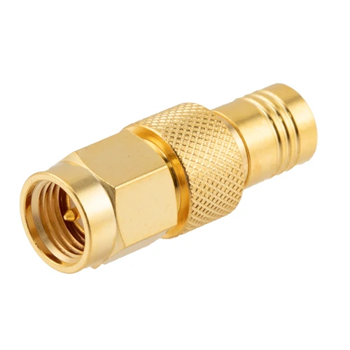
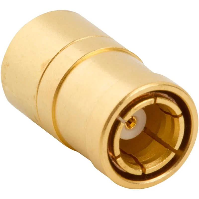
Straight gold-plated SMB to SMA male RF adapter combining a snap-on SMB interface with a threaded SMA connection. Confirm impedance, frequency range, mating geometry, and mechanical loading before use.
Among different conversion options, SMB male to SMA female adapter is frequently requested because many compact RF modules use SMB interfaces internally while external testing or cabling systems use SMA connectors.
This configuration is common in:
- RF test fixtures
- GPS and GNSS modules
- wireless communication equipment
- embedded RF systems
- laboratory measurement setups
However, the adapter should not be selected only by popularity. The actual port geometry and mechanical environment determine whether a rigid adapter is suitable.
Build a two-interface identification sheet before ordering
A simple interface record can prevent incorrect RF purchasing decisions.
SMB–SMA Port Match Sheet
This document is especially useful when several similar adapters exist in the BOM.
For production sourcing, the adapter description should include both interfaces instead of a shortened name.
A better RFQ description:
SMB plug to SMA female straight adapter, 50 ohm, operating frequency requirement specified, drawing confirmation required.
A weak description:
SMB-SMA adapter
The second version leaves too many variables open.
Why does the snap-on side change the mechanical design?
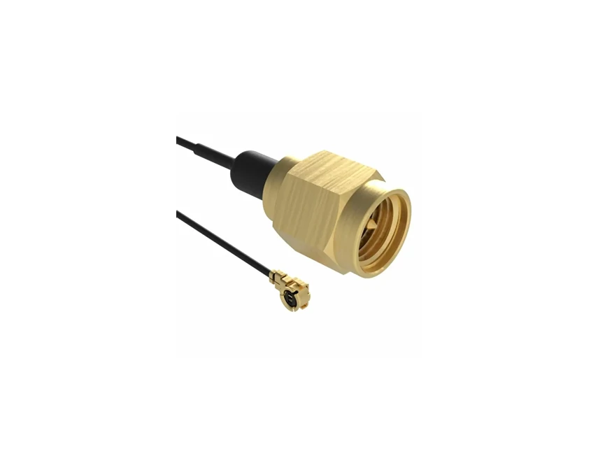
Flexible RF adapter cable assembly with an SMA male connector and a miniature snap-on interface, suitable for compact RF modules and mechanically isolated connections.
The electrical connection may appear simple, but the mechanical design is where many SMB-to-SMA transitions fail.
SMB and SMA use different coupling methods.
SMB relies on a snap-on connection. It is designed for compact equipment where fast mating and limited installation space are priorities.
SMA uses a threaded coupling mechanism. The operator applies tightening torque to achieve a stable mechanical connection.
When these two systems are combined into one rigid adapter, the adapter body becomes the point where two different mechanical behaviors meet.
A small adapter may look strong on the bench. The problem appears when an external SMA cable creates additional force.
Treat SMB retention and SMA torque as different load mechanisms
The SMA side can introduce:
- rotational torque during tightening
- pulling force from cable movement
- bending force from cable weight
- repeated mechanical stress during maintenance
The SMB side may not be designed to absorb these forces directly, especially when mounted on a PCB.
The part may still pass continuity testing.
The failure appears only after vibration, movement, repeated mating, or final installation.
Stop SMA tightening torque from reaching the SMB port
During installation, check:
- Whether the adapter body can be held securely
- Whether the SMA side has enough wrench access
- Whether the cable twists during tightening
- Whether the PCB-mounted SMB connector has mechanical support
- Whether the adapter extends too far from the mounting surface
For applications with frequent service access, a rigid adapter may not always be the best choice.
A short flexible SMB-to-SMA cable assembly can sometimes reduce mechanical stress by separating the two connector positions.
Estimate whether the SMA cable creates a lever effect
A simple mechanical screening method is:
- bending moment applied to the SMB port
- cable or adapter side force
- distance between the support point and applied load
The longer the adapter body and the heavier the external cable, the larger the bending moment.
SMB Port Load Screening
| Factor | Low Risk | Medium Risk | High Risk |
| SMA cable weight | Light cable | Medium cable | Heavy cable |
| Adapter length | Short | Medium | Long |
| Cable support distance | Near support | Moderate | Unsupported |
| Device vibration | None | Occasional | Continuous |
| SMB PCB support | Strong | Moderate | Minimal |
This type of screening is useful before moving from prototype quantities to production.
A transition that works for five laboratory samples may not survive thousands of field installations.
How do you confirm the adapter stays inside a 50-ohm signal path?
A connector conversion can be mechanically correct and still introduce problems into the RF chain.
This is especially true for SMB to SMA transitions because the adapter adds another interface, another contact region, and another impedance transition between the equipment port and the coaxial cable.
A common mistake during sourcing is checking only whether the connector mates correctly.
Every element can influence:
- impedance matching
- insertion loss
- return loss
- VSWR
- frequency response
An adapter should not be treated as an invisible mechanical converter.
Verify every impedance label separately
For a typical RF system, confirm the impedance of each section:
| RF Path Element | Verification Method |
| Device SMB port | Equipment datasheet |
| SMB adapter interface | Supplier specification |
| Internal adapter structure | Drawing / RF data |
| SMA interface | Connector specification |
| Coaxial cable | Cable datasheet |
| Final RF load | System specification |
A supplier statement such as “50-ohm SMB to SMA adapter” is useful, but the actual operating frequency and test data still need confirmation.
The adapter may meet a 50-ohm requirement at a certain frequency range but perform differently near the upper operating limit.
Keep 75-ohm assumptions away from 50-ohm RF systems
SMB connectors are available in different applications, and appearance alone should not be used to determine impedance.
A connector labeled SMB does not automatically define the complete electrical specification.
For a 50-ohm RF application, confirm:
- impedance
- frequency range
- VSWR requirement
- insertion loss
- mating interface
This is especially important when replacing legacy communication equipment or mixed RF systems.
A 50-ohm SMB to SMA adapter should be selected based on verified RF specifications rather than connector appearance.
Use an impedance-chain audit before approving production
50-Ohm Path Audit
All RF path elements should match the required impedance and operate within the specified frequency range.
This simple record helps prevent a common procurement problem: approving a connector based on mechanical fit while ignoring the complete signal path.
Should the adapter be straight, right-angle, or panel-supported?
The body style of an SMB to SMA adapter is not only a packaging decision.
The adapter geometry changes:
- cable routing
- mechanical stress
- connector loading
- installation accessibility
A straight adapter may work well in an open test environment but create unnecessary stress inside a compact enclosure.
Pick a straight body when the cable leaves on-axis
A straight SMB to SMA adapter is normally suitable for:
- laboratory test setups
- short SMA jumper cables
- aligned connector locations
- low mechanical movement applications
- temporary RF connections
The advantages are simple:
- shorter signal path
- easier inspection
- fewer mechanical bends
- simpler manufacturing
However, the cable direction must be considered.
A straight adapter combined with a heavy SMA cable can create a long unsupported structure.
The electrical connection may remain stable while the SMB port experiences continuous mechanical loading.
Turn the transition 90 degrees only when clearance demands it
A right angle SMB to SMA adapter is often selected when the enclosure height or PCB layout does not allow a straight connection.
Before selecting a right-angle structure, check:
- PCB clearance
- SMA nut access
- cable exit direction
- nearby components
- adapter rotation after installation
- side load on the SMB port
A right-angle adapter can solve a space problem, but it may create a routing problem.
The cable should not be forced into position after installation.
Mechanical stress from cable bending can transfer directly into the SMB connection.
Move the SMA connection to the panel when the external cable is heavy
For external RF cables, especially larger coaxial assemblies, a rigid adapter directly mounted on a PCB connector may not be the best architecture.
The flexible connection can isolate:
- cable weight
- vibration
- installation movement
- repeated service stress
This is why adapter cables are often preferred in production equipment.
A rigid adapter is excellent when the mechanical environment is controlled.
A flexible transition becomes more attractive when the connector itself is carrying mechanical load.
Compare four SMB-to-SMA integration layouts
| Requirement | Straight Rigid | Right Angle Rigid | Panel Supported | Flexible Cable |
| Axial clearance | Good | Limited | Good | Excellent |
| Side clearance | Limited | Good | Excellent | Excellent |
| SMB port load | Medium | Medium | Low | Lowest |
| Cable routing freedom | Low | Medium | High | Highest |
| Frequent maintenance | Medium | Medium | High | High |
| Heavy external cable | Poor | Limited | Good | Best |
| Main risk | Cable leverage | Side force | Additional assembly | Cable specification |
The correct choice depends on the installation environment, not only the connector conversion.
How much insertion loss should the transition be allowed to add?
An SMB to SMA adapter introduces a small additional RF path.
For low-frequency systems, the impact may be minor.
For higher-frequency measurement systems, the adapter becomes part of the RF measurement chain and must be included in the test plan.
A statement such as:
“The adapter has low loss.”
is incomplete.
A buyer should ask:
- At what frequency?
- Under what test condition?
- With which cable?
- Measured using what calibration method?
Define the reference planes before measuring
Insertion loss measurement should define the complete setup:
- Calibration plane A
- Calibration plane B
- Test cables
- Adapter orientation
- Connector cleaning condition
- Frequency sweep range
- Mating condition
Without defined reference planes, two suppliers can measure the same adapter and report different results.
Compare the adapter path against a baseline
The added loss can be calculated as:
ILadded(f)=ILwith adapter(f)−ILreference(f)
Where:
- ILadded(f) = additional loss introduced by the adapter
- ILwith adapter(f) = measured path including adapter
- ILreference(f) = baseline path without adapter
SMB-to-SMA Added-Loss Calculation
This format is more useful than a single average loss number.
RF systems do not always fail because of average loss. Problems often appear at specific frequency points.
Track return loss as well as insertion loss
A transition can have acceptable insertion loss while still creating mismatch.
For production approval, consider:
- Maximum insertion loss
- Minimum return loss
- Maximum VSWR
- Required frequency band
- Test fixture
- Calibration method
A VNA sweep provides a clearer picture than a simple continuity check.
Continuity confirms that the conductor is connected.
It does not confirm that the RF transition is behaving correctly.
Retest after repeated mating cycles
SMB uses a snap-on connection, so repeated connection cycles can affect:
- contact pressure
- retention force
- RF repeatability
For applications with frequent maintenance, evaluate the adapter after multiple mating cycles.
The acceptance criteria should include both:
- mechanical retention
- RF performance stability
A part that performs well when new may not behave the same after repeated service.
When is an SMB to SMA cable a better engineering choice?
A rigid SMB to SMA adapter solves one problem: converting one connector interface into another.
However, it also creates a fixed mechanical connection between two ports that may not have been designed to carry additional load.
This is where an SMB to SMA cable or SMB to SMA adapter cable becomes a better option.
The difference is not only flexibility.
A cable assembly changes how mechanical stress travels through the RF system.
A rigid adapter transfers movement directly between the SMB and SMA ports.
A flexible cable assembly absorbs part of that movement through:
- cable flexibility
- routing distance
- strain relief structure
- controlled bending radius
For PCB-mounted SMB connectors, this difference can determine long-term reliability.
Switch to a flexible link when the ports are not naturally aligned
A flexible SMB-to-SMA connection is usually worth considering when:
- the SMB port is mounted directly on a PCB
- the SMA cable will move during operation
- the external cable is relatively stiff
- connector axes are not aligned
- the equipment experiences vibration
- technicians frequently reconnect the system
- the adapter has no mechanical support
- enclosure space is limited
A short cable section can reduce stress on the PCB connector because the SMA connector no longer acts as a lever arm.
The cable becomes a mechanical buffer between two connector standards.
Use cable compliance to isolate a PCB connector
The flexible option can reduce several common installation problems:
| Problem | Rigid Adapter Risk | Flexible Cable Advantage |
| Cable pulling force | Transfers to SMB port | Absorbed by cable |
| Vibration | Direct mechanical transfer | Reduced transfer |
| Port misalignment | Adapter forced into position | Cable compensates |
| Repeated service | Connector stress increases | Lower connector loading |
| Tight enclosure | Limited movement | Easier routing |
However, the cable assembly introduces new selection factors.
A buyer should also specify:
- cable type
- cable length
- impedance
- frequency range
- bend radius
- connector termination
- insertion loss
- VSWR requirement
A flexible connection does not remove RF considerations.
The cable itself becomes part of the RF path.
Keep the adapter and cable intents separate
The purpose of this article is:
SMB to SMAadapter = rigid interface conversion selection
A future cable-focused article should cover:
SMB to SMA cable = coax selection, cable length, attenuation, routing, and strain relief
Mixing both topics together often creates confusion during sourcing.
A buyer looking for a rigid transition may not need a cable assembly.
A buyer facing mechanical problems may need the cable solution instead.
Score the switch-to-cable decision
Use the following screening method.
Add one point for each “Yes”.
Rigid-or-Flexible Decision Score
Recommended interpretation:
| Score | Recommendation |
| 0–2 | Rigid adapter is usually acceptable |
| 3–4 | Add mechanical support and review installation |
| 5–8 | Flexible SMB-to-SMA cable is strongly preferred |
This type of decision tool helps avoid a common mistake: selecting the cheapest transition first and solving mechanical failures later.
How should SMB male to SMA female parts be specified on an RFQ?
Many adapter sourcing problems start with incomplete purchasing descriptions.
A request such as:
“Need SMB to SMA adapter”
does not define enough information for reliable production.
The supplier still needs to determine:
- which SMB interface
- which SMA interface
- impedance
- frequency requirement
- mechanical structure
- inspection criteria
A better RFQ description reduces communication cycles and prevents incorrect samples.
Stop relying on a short product title
Instead of:
SMB-SMA Adapter
Specify:
SMB plug to SMA female straight adapter, 50 ohm, operating frequency requirement specified, mechanical drawing required.
This immediately defines:
- SMB side
- SMA side
- body style
- impedance expectation
Define all interface fields
A complete adapter request should include:
| Requirement | Buyer Specification |
| SMB interface | Plug / Jack |
| SMA interface | Male / Female |
| Center contact | Pin / Socket |
| Coupling style | Snap-on / Threaded |
| Impedance | 50 ohm |
| Frequency range | Required band |
| Body style | Straight / Right angle |
| Installation | Cable / PCB / Panel |
| Application | Test / Production / Field |
The more precise the initial request, the lower the risk of receiving a mechanically compatible but electrically unsuitable part.
Add measurable RF limits
Avoid requesting only:
“Low loss adapter”
Instead define:
- Maximum insertion loss
- Minimum return loss
- Maximum VSWR
- Operating frequency
- Test method
- Required measurement report
For example:
SMB to SMA adapter, 50 ohm, DC–6 GHz, insertion loss limit required, VSWR verification required.
This gives both engineering and procurement teams a measurable target.
Add mechanical acceptance fields
RF performance is only part of the acceptance process.
Include:
- Overall length
- Maximum body diameter
- SMB retention requirement
- SMA thread inspection
- Expected mating cycles
- Temperature range
- Material
- Plating requirement
A connector that performs correctly in RF testing may still fail installation requirements if the mechanical dimensions are wrong.
How should the first article be qualified before volume production?
A sample that mates correctly is only the beginning.
Before approving a production lot, verify the adapter in the actual application environment.
A laboratory bench test alone may not reveal:
- enclosure interference
- cable loading
- connector movement
- assembly difficulty
- RF variation after installation
Inspect mating interfaces under magnification
First article inspection should check:
- SMB contact geometry
- snap surface condition
- SMA thread condition
- center pin/socket alignment
- dielectric condition
- metal contamination
- plating defects
- concentricity
Mechanical defects can later become RF problems.
Verify the adapter in the actual equipment fixture
Do not approve a part only because:
“It can be connected.”
The installed condition should be checked.
Verify:
- PCB clearance
- cable wrench access
- adapter rotation
- enclosure closing
- cable load
- nearby component interference
The actual equipment environment determines whether the adapter design is suitable.
Sweep the complete RF range
For RF products, the final verification should include:
- insertion loss
- return loss
- VSWR
- continuity
- frequency sweep
The measurement should cover the required operating band.
A connector transition that works at low frequency may show different behavior near the upper limit.
Use a first-article acceptance table
First Article Acceptance Standard
| Test | Condition | Limit | Evidence |
| Interface match | Unmated | Drawing confirmation | Photo |
| SMB retention | Mated | Project requirement | Test record |
| SMA thread fit | Gauge / mating check | Pass | Inspection sheet |
| Continuity | Static | Pass | Test log |
| Insertion loss | Full band | RFQ limit | S2P/PDF |
| Return loss | Full band | RFQ limit | S2P/PDF |
| Installed fit | Final fixture | No interference | Photo |
| Movement check | Installed | No intermittent fault | Test record |
How should production lots be screened for repeatability?
After approval, production consistency becomes the next concern.
A connector adapter is a precision mechanical and RF component.
Small process changes can affect:
- contact alignment
- plating condition
- retention force
- RF response
Apply 100% checks to visible interface defects
Recommended 100% inspection:
- correct interface combination
- center contact damage
- SMA thread damage
- SMB body deformation
- contamination
- incorrect labeling
These defects are usually easy to identify before shipment.
Use sampling for RF and mechanical measurements
Sampling can include:
- SMB retention
- insertion loss
- return loss
- dimensional consistency
- repeated mating performance
Increase inspection after:
- new supplier introduction
- machining process change
- plating change
- drawing revision
- customer complaint
- failed production lot
Diagnose connection problems without replacing every component
When an SMB to SMA adapter system fails, replacing every component immediately can hide the actual cause.
Separate mechanical symptoms from RF symptoms.
Separate retention problems from RF mismatch
Mechanical symptoms:
- loose connection
- adapter movement
- unexpected disconnect
RF symptoms:
- increased return loss
- frequency-specific notch
- unstable insertion loss
- changing measurement results after movement
The troubleshooting process should identify whether the issue is:
- connector contact
- cable stress
- adapter design
- installation condition
- RF mismatch
Swap one element at a time
Change only one component at a time.
This prevents replacing a good adapter because of a cable or installation problem.
Compare free-state and installed-state performance
A useful diagnostic method:
- Test the adapter on the bench.
- Install the cable assembly.
- Apply normal mechanical routing.
- Repeat RF measurement.
FAQ
Can a wrong SMB to SMA adapter still physically connect?
Yes. Mechanical mating does not always confirm correct gender, impedance, polarity, or RF performance. Always verify the complete interface specification before approval.
Can an SMB to SMA adapter operate above 4 GHz?
The usable frequency depends on the specific adapter design and verified RF data. Do not assume performance only from the SMB connector family name. Confirm S-parameter data and application requirements.
When should I choose an SMB to SMA cable instead of a rigid adapter?
Choose a cable solution when the SMB port is PCB-mounted, the SMA cable is heavy or moving, vibration exists, or the installation creates mechanical stress.
Final buying guidance for SMB to SMA adapters
An SMB to SMA adapter is a small component, but it sits at the connection point between two different RF interfaces.
The best selection process is not based on connector appearance or the shortest product description.
Before ordering, define:
- SMB interface
- SMA interface
- impedance
- frequency range
- adapter geometry
- mechanical environment
- RF acceptance limits
- inspection requirements
For standard laboratory connections, a rigid adapter may be enough.
For PCB-mounted systems, vibration environments, or production equipment, a flexible SMB-to-SMA cable assembly may provide a safer mechanical solution.
If the assembly will operate near the upper frequency range, provide the operating frequency, cable type, length, connector combination, and inspection target before sourcing. These details help determine whether a standard adapter is suitable or whether a customized RF transition should be evaluated.
