
A customer once asked for a 30 cm WiFi antenna cable replacement. The connector was the same, the cable looked similar, and the sample passed a basic connection test.
The problem came later.
After installation into the enclosure, the antenna position changed slightly. The cable had to follow a different routing path, and the final wireless result was not identical to the original sample.
This type of issue is easy to miss during purchasing. Many antenna cable problems are not caused by the connector itself. They appear after the cable becomes part of the complete device structure.
A wifi antenna extension cable is often treated as a small accessory, but for RF equipment it is part of the signal path. The cable length, internal construction, connector matching, and installation method all influence the final application.
For engineers and buyers, the key question is not only “Can this cable connect?” The more useful question is “Will this cable still work after it is installed in the real product?”
Why Are WiFi Antenna Extension Cables Used in Wireless Devices?
Wireless modules and antennas are not always placed close together.
During product development, the PCB layout is usually decided by many factors. The RF module may need to stay close to the main processor.
Common examples include:
| Device | Reason for Using Extension Cable |
| WiFi Router | External antenna installation |
| IoT Gateway | Flexible antenna positioning |
| Smart Device | Limited internal PCB space |
| Industrial Controller | Antenna separation from enclosure |
A small cable change can sometimes solve a mechanical problem.
For example, an IoT controller may use a compact wireless module inside a plastic housing. The antenna connector may not be located near the ideal mounting position. Instead of changing the PCB, engineers can use a cable assembly to move the antenna to the outside area.
The important point is that the extension cable only changes the connection location. It does not add transmission power or improve the antenna design itself.
What Should Be Checked Before Choosing a WiFi Antenna Extension Cable?
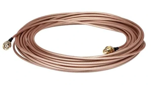
This image shows a long coaxial WiFi antenna extension cable with SMA connectors. It is suitable for antenna relocation, RF signal transmission, wireless equipment installation, and applications requiring a longer cable route between the WiFi module and external antenna.
The first sample request often starts with a connector name:
“SMA to antenna cable.”
That description is usually not enough.
Different projects may use the same connector family but require different cable structures.
Before ordering, confirm the complete cable information.
| Item | Example |
| Connector Side A | SMA, RP-SMA, IPEX |
| Connector Side B | Antenna connector |
| Cable Type | RG316, RG178, 1.13mm coax |
| Impedance | 50Ω |
| Frequency | 2.4GHz / 5GHz |
| Length | Actual installation length |
A supplier can only evaluate the cable correctly when these details are clear.
Check the Connector Before Checking the Cable Length
Connector mismatch is one of the easiest problems to create.
SMA and RP-SMA are frequently used in WiFi products. They have similar mechanical dimensions, so they are sometimes confused during purchasing.
The outside thread may fit, but the internal contact structure is different.
This means a cable can appear to install normally while the RF connection is not correct.
For projects using small wireless modules, miniature connectors such as IPEX or MMCX are also common. These connectors save PCB space, but they require more attention during assembly because the mating structure is smaller and more sensitive.
A complete specification should include:
- connector model;
- connector gender;
- polarity;
- cable direction;
- required antenna interface.
Select Cable Length Based on Installation, Not Guesswork
Cable length is usually decided after the mechanical design becomes clearer.
A common mistake is measuring only the distance between two connection points. The actual cable route may include:
- bending areas;
- fixing points;
- enclosure edges;
- strain relief sections.
A 20 cm straight distance does not always mean a 20 cm cable is suitable.
Too short:
- cable may be pulled during installation;
- connector joints may receive mechanical stress;
- assembly becomes difficult.
Too long:
- additional attenuation is introduced;
- extra cable may create unwanted routing space.
For production projects, the final installed position should be considered before confirming the cable length.
WiFi Extension Cable RF Selection Notes
| Situation | Recommended Check |
| Compact wireless module | Confirm miniature connector type |
| External antenna | Check SMA/RP-SMA compatibility |
| Longer cable requirement | Review cable attenuation |
| 5GHz application | Confirm frequency capability |
| Mass production | Request sample test before release |
A cable that works in a laboratory setup may still need verification after enclosure installation. The physical environment often changes the final RF condition.
How Do SMA and RP-SMA Interfaces Affect Extension Cable Compatibility?
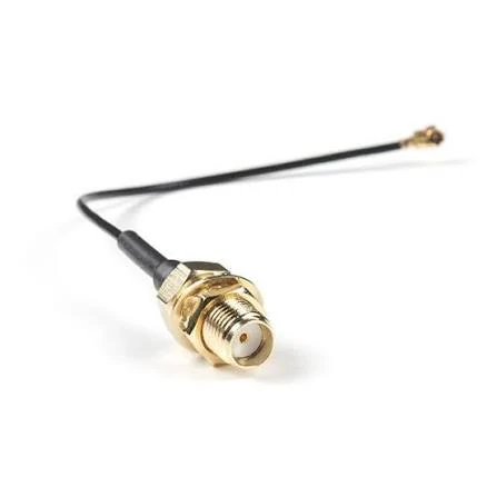
This image shows a panel mount SMA female WiFi antenna extension cable connected to a miniature RF connector. It is commonly used in embedded wireless devices, IoT equipment, routers, and enclosure-mounted antenna applications where the antenna needs to be moved away from the PCB.
A cable can arrive with the correct length and the correct appearance, but still fail during installation because the connector interface was not confirmed carefully.
This happens frequently with WiFi equipment.
SMA and RP-SMA connectors are widely used in wireless products. From the outside, they look almost identical. Both use threaded coupling, and both are commonly seen on external antennas, routers, and wireless modules.
The difference is inside the connector.
Standard SMA and RP-SMA use different center contact arrangements. One uses a pin structure, while the other uses a socket structure. If the wrong type is selected, the connector may not establish the expected electrical connection.
For product development, connector names should not be the only information written in the BOM.
A more complete description should include:
- connector series;
- male or female interface;
- standard or reverse polarity;
- cable side and antenna side;
- application frequency.
How Can Connector Mistakes Affect Wireless Products?
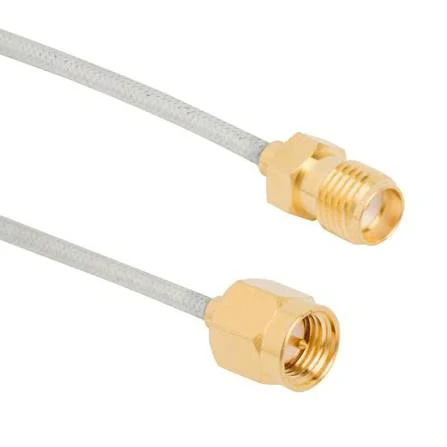
This image shows an SMA male to SMA female WiFi antenna extension cable with a white coaxial cable. It is used for wireless modules, antenna relocation, RF equipment installation, and custom WiFi cable assemblies where connector matching and cable length are important.
Connector problems are usually discovered after assembly, not during purchasing.
A supplier may receive a request such as:
“SMA WiFi antenna extension cable, 50 cm.”
From a production perspective, several questions are still unanswered.
Is it SMA male to SMA female?
Is it RP-SMA?
Is the antenna side the same interface?
Does the cable connect directly to the module or through an adapter?
A small interface difference can create unnecessary replacement work, especially when hundreds or thousands of cables have already been assembled into finished products.
For prototype quantities, engineers can usually identify the problem quickly. For mass production, the cost is much higher because the issue may involve:
- assembly downtime;
- replacement labor;
- returned products;
- additional inspection.
How Does Cable Length Influence WiFi Signal Loss?
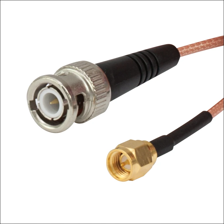
This image shows a BNC to SMA coaxial RF adapter cable. It can be used for RF testing, antenna connection, wireless devices, laboratory equipment, and signal transmission applications where BNC and SMA interfaces need to be connected.
The cable length decision is usually a compromise.
During mechanical design, a longer cable looks attractive because it makes installation easier. The antenna can be placed wherever the enclosure requires.
From the RF side, every extra section of coaxial cable introduces loss.
For example, a low-diameter coax cable used inside an IoT device may provide good flexibility, but its attenuation is usually higher than larger low-loss cables.
The engineer needs to decide whether the installation benefit is worth the additional loss.
WiFi Extension Cable Loss Evaluation
| Factor | Effect on RF System |
| Longer cable | Higher signal attenuation |
| Smaller cable diameter | Better flexibility, usually higher loss |
| Higher frequency | More sensitive to cable loss |
| More connectors | Additional insertion loss |
| Extra adapters | Adds another RF transition |
A cable that works well at 2.4GHz may need additional evaluation when the same design is used for 5GHz operation.
The reason is not only the cable itself. Connector quality, assembly accuracy, and routing conditions also become more noticeable at higher frequencies.
How Should Engineers Balance Cable Length and Installation Space?
The shortest possible cable is not always the correct choice.
A very short cable may create mechanical problems:
- excessive bending near the connector;
- tension on the mating interface;
- difficulty during assembly.
This is especially important for miniature connectors. Interfaces such as IPEX/U.FL are designed for compact equipment, but repeated mechanical stress can affect long-term reliability.
A slightly longer cable with proper routing may perform better than a shorter cable installed under pressure.
For production products, the cable should be evaluated in the actual enclosure.
A sample tested on a workbench represents only one condition. The final product may include:
- different cable bending angles;
- nearby power circuits;
- plastic or metal enclosure effects;
- antenna mounting changes.
How Do Cable Materials Affect WiFi Antenna Extension Performance?
The cable type is another decision point that is often overlooked.
Many buyers focus on the connector because it is visible. The coaxial cable inside the assembly is equally important.
Different cable constructions provide different combinations of flexibility, size, and attenuation.
Common options for WiFi antenna extension applications include:
| Cable Type | Typical Advantage | Common Application |
| RG178 | Small diameter | Compact wireless devices |
| RG316 | Flexible structure | General RF cable assemblies |
| 1.13mm Coax | Lightweight and space saving | Embedded modules |
| Low Loss Coax | Lower attenuation | Longer cable distance |
When Is RG316 a Practical Choice?
Its advantages are related to mechanical flexibility and availability. It can handle many internal routing requirements without requiring large installation space.
Typical applications include:
- WiFi modules;
- GPS devices;
- IoT products;
- test connections.
However, RG316 is not automatically suitable for every design.
If the cable length becomes longer or the operating frequency increases, attenuation needs to be checked.
The cable choice should follow the application requirement rather than simply selecting the smallest diameter option.
Why Does Cable Structure Matter in RF Applications?
Two cables using the same cable model may show different results if the termination process is inconsistent.
Issues such as:
- poor crimping;
- damaged dielectric;
- loose shielding contact;
- incorrect stripping length;
can influence the final RF performance.
For this reason, cable selection and assembly control should be considered together.
How Should Custom WiFi Antenna Extension Cables Be Specified?
A cable drawing usually tells more than a product name.
During RF cable sourcing, one of the common problems is that the first request contains only a short description:
“Need a WiFi antenna extension cable.”
From the supplier side, many details are still missing.
The same description could represent several different assemblies:
- SMA to SMA cable for an external antenna;
- IPEX to SMA cable for an embedded module;
- RP-SMA cable for a router;
- miniature coax cable for an IoT device.
They may all be called WiFi antenna cables, but the manufacturing process and final application are not the same.
For custom production, the basic information normally includes:
| Item | Example Information |
| Connector combination | IPEX to SMA / SMA to RP-SMA |
| Cable model | RG316 / RG178 / 1.13mm coax |
| Length | 100mm / 300mm / 500mm |
| Frequency | 2.4GHz / 5GHz |
| Impedance | 50Ω |
| Test requirement | VSWR / insertion loss |
A clear specification helps avoid unnecessary sample changes.
This is especially important when the cable becomes part of a finished product. Changing the connector after assembly is not only a component replacement. It may involve enclosure modification, production interruption, and additional testing.
Why Does the Actual Installation Environment Matter?
A cable that works in a sample test does not always behave the same way inside the final device.
During product assembly, the cable may pass through a different route than expected.
The actual installation may include:
- narrow internal spaces;
- sharp bending areas;
- nearby power components;
- fixed mounting points;
- repeated movement during maintenance.
These details influence cable selection.
For example, an ultra-thin coax cable is attractive for compact equipment because it takes less space. However, the designer still needs to check whether the cable can handle the required bending and whether the signal loss is acceptable at the operating frequency.
The smallest cable is not automatically the correct cable.
Why Are Cable Drawings Useful for OEM Projects?
Text descriptions work well for standard products.
Custom assemblies are different.
A simple drawing can show information that is difficult to explain through words:
- connector direction;
- cable exit angle;
- exposed cable length;
- mounting position;
- bend requirement.
This becomes important when the cable needs to fit inside a fixed enclosure.
A connector may be electrically correct but mechanically unsuitable. The cable may exit in the wrong direction or create pressure on the PCB after installation.
How Should WiFi Antenna Extension Cables Be Tested Before Shipment?
Many cable inspections begin with appearance checking.
The connector looks normal. The cable length matches the order. The label is correct.
A cable assembly can pass continuity testing and still require further evaluation before being used in a wireless product.
Common inspection items include:
| Inspection | What It Checks |
| Continuity | Electrical connection path |
| VSWR | Matching condition |
| Insertion Loss | Signal reduction |
| Dimension Check | Length and structure |
| Appearance Check | Assembly condition |
Why Is RF Testing Different From Basic Electrical Testing?
These problems may not be visible from the outside.
The required test level depends on the application.
A short internal cable for a consumer device may have different inspection requirements compared with a test cable or industrial wireless system.
What Should Suppliers and Buyers Confirm Before Mass Production?
Small differences between sample and production can create unexpected results.
For example, changing from one cable diameter to another may make installation easier, but it can also change attenuation and mechanical behavior.
Production consistency matters as much as the first sample performance.
FAQ
Can a longer extension cable be used if the connector is correct?
A longer cable may physically work, but the additional length increases RF loss.
Is a thinner cable always better for WiFi equipment?
Not necessarily. Thin cables are easier to route, especially inside compact products, but cable size, attenuation, and mechanical requirements need to be considered together.
What information should be provided when requesting a quotation?
The most useful information includes connector type, cable length, cable model, frequency range, impedance, application environment, and required testing.
What information should be provided for a custom WiFi antenna extension cable quotation?
A connector name alone usually cannot define the cable assembly. A quotation request should include the connector combination, cable model, required length, frequency range, impedance, and installation condition. For OEM projects, a drawing or sample is helpful because connector direction and cable routing can affect the final assembly.
Final Selection Note
A WiFi antenna extension cable is a small part inside a wireless system, but it connects several important elements together.
The connector must match the device.
The cable must fit the installation.
The assembly must maintain the expected RF characteristics.
For standard applications, a basic cable specification may be enough. For OEM products and repeated production, clearer information at the beginning usually prevents problems later.
When requesting a custom cable, providing the actual installation condition is often as important as providing the connector model.
