
A test setup can look correct and still give a misleading result.
A common situation in RF labs is that a new module arrives with an SMA port, while the available test cable or instrument uses BNC. The connection problem seems simple: find an adapter, screw it on, and continue testing.
The problem is that RF conversion is rarely only a mechanical issue.
A sma to bnc adapter may physically connect two devices, but the engineer still needs to check the connector gender, impedance, frequency range, and the role of that adapter in the complete RF path.
For a basic signal check, the adapter choice may not create an obvious problem. In a measurement system, especially when checking VSWR, return loss, or insertion loss, small differences in the RF path can affect the result.
How Do SMA to BNC Adapters Fit Different RF Test Systems?
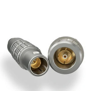
This image shows an SMA to BNC adapter with precision-machined metal housing and coaxial contact structure. The adapter allows SMA and BNC interfaces to be connected while maintaining reliable RF signal transmission performance.
SMA and BNC are both widely used coaxial interfaces, but they usually appear in different parts of a system.
An engineer may have a spectrum analyzer with a BNC cable available but need to connect it to an RF module using SMA. Instead of changing the cable system or modifying the equipment interface, an adapter provides a simple transition.
The important point is that the adapter becomes part of the RF chain.
A complete connection is no longer:
Equipment → Cable
It becomes:
Equipment → Adapter → Cable → Device
Every additional interface adds another contact point. In low-frequency applications, this may have little impact. In higher-frequency applications, the connector structure, machining accuracy, and mating condition become more important.
Where Are SMA to BNC Adapters Commonly Used?
The most common use is not permanent installation. Many are used during development, debugging, and testing.
| Application | Typical Connection | Reason for Using Adapter |
| RF module testing | SMA module to BNC instrument cable | Use existing laboratory equipment |
| Prototype verification | SMA PCB port to BNC test lead | Avoid changing prototype hardware |
| Antenna evaluation | SMA antenna connector to BNC cable | Flexible test setup |
| Production inspection | SMA product interface to BNC tester | Support different test fixtures |
A supplier receiving an RF adapter inquiry should usually ask one additional question:
“Is this adapter for a test bench or for a final installed product?”
The answer affects the selection.
A laboratory adapter may prioritize measurement consistency. A production-installed adapter may require stronger mechanical durability, better environmental protection, or longer mating life.
Why Should Engineers Check the Adapter Instead of Only the Connector Shape?
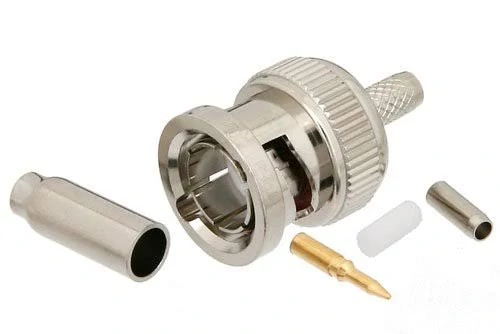
This image displays the internal components of a BNC connector. The connector structure includes the signal contact, outer conductor connection area, and mechanical fixing parts used for coaxial cable installation.
One of the easiest mistakes in RF sourcing is selecting by appearance.
A connector that fits mechanically is not automatically suitable for the RF application.
Before ordering an SMA to BNC adapter, the basic specification should include:
| Required Information | Example |
| SMA interface | SMA male / SMA female |
| BNC interface | BNC male / BNC female |
| Impedance | 50Ω |
| Frequency requirement | DC–6 GHz |
| Application | Test equipment / antenna / module |
| Quantity | Sample or production batch |
This information prevents a common purchasing loop:
Wrong adapter received → additional confirmation → replacement order → delayed testing.
For small quantities this may only waste time. For production projects, an incorrect interface specification can affect the entire validation schedule.
What Is the Difference Between an RF Connector and an Adapter?
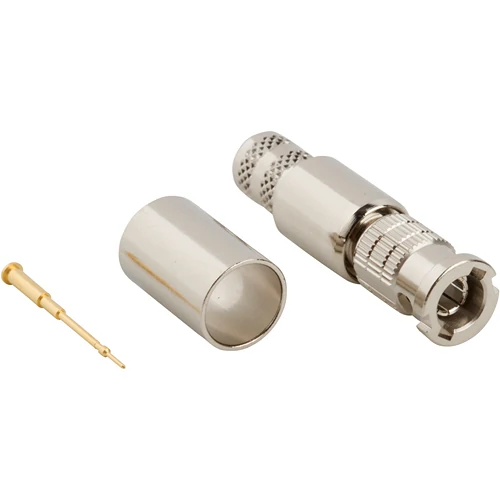
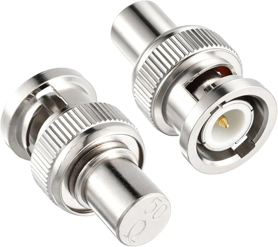
This image shows a BNC RF adapter with a durable metal housing and coaxial contact structure. The 50 ohm impedance design is widely used in RF applications requiring accurate signal transmission and measurement.
The terms are sometimes mixed during communication between engineering and purchasing teams.
A connector is part of an assembly.
Examples:
- SMA plug installed on an RG316 cable
- BNC connector installed on a test lead
- SMA jack mounted on a PCB
An adapter is used to connect existing interfaces.
Examples:
- SMA equipment port connected to BNC cable
- BNC instrument connected to SMA test fixture
This difference is important when preparing a BOM.
A BOM item written only as:
“RF adapter”
does not provide enough information for production purchasing.
How Do SMA and BNC Mechanical Interfaces Affect Adapter Selection?
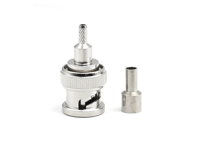
This image presents individual BNC connector components including the center contact pin, connector shell, and sleeve parts. The modular design allows the connector to be assembled with different coaxial cables according to application requirements.
The different designs explain why adapters exist.
An SMA port on a small wireless module may need to connect with a BNC cable already available in the laboratory. The adapter solves the mechanical mismatch, but the electrical specification still needs confirmation.
A practical selection order is:
- Confirm SMA and BNC interfaces
- Confirm male/female combination
- Confirm impedance
- Confirm frequency range
- Confirm application environment
This sequence is usually faster than selecting a product only from a catalog picture and correcting the mistake later.
How Should You Check Impedance Before Using an SMA to BNC Adapter?
This image shows BNC connector parts prepared for cable assembly. The components are designed to support reliable mechanical connection, impedance matching, and signal integrity in RF applications.
A replacement adapter often arrives because the original cable or instrument interface does not match.
At that moment, many purchasing requests only contain one sentence:
“SMA to BNC adapter, please quote.”
For general connection purposes, this information is not enough.
The first question from an RF engineer is usually not the connector type. It is:
“Is this a 50Ω path or a 75Ω path?”
That difference is easy to miss because the BNC interface is used in both applications.
Most SMA systems used in RF communication, antenna testing, and microwave equipment are based on 50Ω impedance. BNC, however, has a wider application range.
50Ω BNC is commonly used in:
- RF test equipment
- signal measurement systems
- communication equipment
75Ω BNC is commonly used in:
- video systems
- broadcast equipment
- some transmission applications
The connector can mate. The measurement result may still change.
Why Can a Wrong Impedance Adapter Pass Basic Testing?
A simple continuity test only checks whether electricity can pass through the connection.
It does not show whether the RF signal is being transferred correctly.
This is a situation frequently seen during prototype testing.
An engineer connects a module output through an SMA to BNC adapter, checks that the signal appears on the instrument, and continues development.
Later, during antenna tuning or final verification, the measured value is different from the expected result.
The adapter may not be the only possible reason, but it is one of the items that should be reviewed.
The RF path should be considered as a complete chain:
RF source → cable → adapter → cable → device
Not as individual components.
A mismatch anywhere in this path can influence:
- VSWR measurement
- return loss result
- calibration accuracy
- repeatability between tests
For this reason, professional RF purchasing specifications usually include impedance information.
That one additional line can prevent incorrect quotation and repeated confirmation.
Which SMA and BNC Gender Combination Should Be Selected?
After impedance, the next issue is mechanical matching.
SMA and BNC both have male and female versions. The adapter must match the existing ports, not the connector you happen to have in hand.
Typical combinations include:
| Adapter Type | Connection Example | Common Situation |
| SMA Male to BNC Female | SMA equipment to BNC cable | Test equipment connection |
| SMA Female to BNC Male | SMA cable to BNC instrument | Cable conversion |
| SMA Male to BNC Male | Special cable interface conversion | Custom setups |
| SMA Female to BNC Female | Port extension or connection change | Fixed installations |
A frequent mistake occurs when the buyer confirms only one side.
For example:
“Need SMA to BNC.”
The supplier still needs to know:
- Which side is SMA?
- Which side is BNC?
- Are the existing ports male or female?
How Does Frequency Range Affect SMA to BNC Adapter Selection?
The connector name alone does not define the RF capability.
Two adapters may both be listed as SMA to BNC, but their internal construction can be different.
Important factors include:
- contact design
- dielectric material
- machining tolerance
- plating thickness
- assembly consistency
These details become more noticeable as frequency increases.
For example, an adapter used at 100 MHz in a general signal connection has different requirements from one used near several GHz in an RF measurement setup.
Before selecting an adapter, engineers usually check:
| Parameter | Why It Should Be Confirmed |
| Frequency range | Ensure operation within the required band |
| VSWR | Check impedance behavior |
| Insertion loss | Estimate signal reduction |
| Connector material | Consider durability and stability |
| Mating cycles | Important for repeated laboratory use |
A practical rule is to avoid selecting a component exactly at the operating limit.
RF Frequency Margin Calculation
A simple selection reference:
Frequency Margin Ratio = Adapter Rated Frequency ÷ Actual Operating Frequency
Example:
System frequency: 4 GHz
Option A:
Rated frequency: 6 GHz
6 ÷ 4 = 1.5
Option B:
Rated frequency: 18 GHz
18 ÷ 4 = 4.5
Both may work depending on the application, but the second option leaves more room for future changes.
This is useful when the project may later add:
- longer cables
- additional adapters
- wider frequency testing
- different RF modules
The connector should not become the limiting factor before the system reaches its expected operating range.
What Problems Appear When Too Many Adapters Are Added?
Adapter stacking is another issue that appears during troubleshooting.
A single SMA to BNC adapter is usually straightforward.
The situation changes when the connection becomes:
SMA → BNC adapter → BNC cable → BNC adapter → SMA cable → Device
Each additional interface introduces another mechanical connection.
Possible concerns include:
- increased insertion loss
- additional reflection points
- more mechanical tolerance variation
- reduced repeatability
This does not mean adapters should be avoided.
In many laboratories, adapters are necessary because equipment platforms are different.
The practical approach is controlling the number of transitions.
For measurement-critical applications:
- use the shortest possible connection path;
- avoid unnecessary adapter chains;
- keep cable type consistent;
- verify the complete assembly when results are sensitive.
How Should SMA to BNC Adapters Be Inspected Before Delivery?
Incoming inspection does not need to be complicated, but it should cover the points that can create later problems.
A basic inspection includes:
| Inspection Item | Check Method |
| Interface type | Confirm SMA/BNC specification |
| Gender | Compare with purchase requirement |
| Mechanical fit | Check mating condition |
| Housing | Check scratches or deformation |
| Electrical path | Continuity test |
| RF performance | VSWR or insertion loss test when required |
One important point:
Continuity testing is only a basic electrical check.
It cannot replace RF testing.
A connection may pass continuity but still show unexpected VSWR at the working frequency.
For laboratory accessories, especially those used in calibration or RF verification, inspection requirements should be agreed before purchasing.
What Information Should Engineers Send When Requesting an SMA to BNC Adapter?
An RF adapter request often starts with a very short message.
“Please quote SMA to BNC adapter.”
For a simple replacement, this may be enough.
For engineering projects, it usually creates another round of questions.
The reason is simple. SMA and BNC only describe the interface family. They do not describe the complete product requirement.
The supplier still needs to know what is actually being connected.
A few examples:
A test engineer may need an adapter between an SMA RF module and a BNC measurement cable.
A production department may need the same interface conversion installed on a test fixture.
A customer may only need a small quantity for laboratory debugging.
The product name is identical, but the requirement behind it is different.
Before quotation, engineers normally provide:
- SMA side interface
- BNC side interface
- male or female configuration
- impedance
- frequency requirement
- application
A typical specification could look like this:
SMA male to BNC female adapter, 50 ohm, used for RF test equipment connection, operating frequency up to 6 GHz.
This description gives much more information than only writing “SMA to BNC adapter”.
Why Do Small Specification Differences Matter in RF Purchasing?
In many electronic parts, replacing one similar item may not create a visible problem.
RF components are different.
A connector can fit another connector.
A cable can carry a signal.
A test instrument can display data.
The problem may appear later during measurement or system verification.
For example, a customer may order an SMA to BNC adapter for a prototype test. The first test is successful because the setup is simple and the operating frequency is low.
After the product enters a more detailed verification stage, engineers start checking:
- return loss;
- antenna matching;
- signal stability;
- measurement repeatability.
At this stage, details that were ignored during the first connection become important.
This is why RF purchasing normally requires more information than mechanical compatibility.
The supplier is not only matching two connector shapes.
The supplier is checking whether the adapter belongs to the same RF path.
What Should Be Considered Before Using SMA to BNC Adapters in Production?
A laboratory and a production line usually have different requirements.
For laboratory use, the main concern is often:
“Can the equipment be connected quickly?”
For production use, the questions become different:
“How many times will this connector be mated?”
“Will every operator connect it the same way?”
“Does the batch remain consistent?”
A production test fixture may use the adapter hundreds or thousands of times.
In this case, engineers may pay attention to:
| Item | Reason |
| Connector durability | Repeated connection affects service life |
| Mechanical consistency | Prevent unstable contact |
| Interface accuracy | Avoid assembly problems |
| Batch stability | Keep testing conditions consistent |
A sample that works correctly does not automatically represent every production requirement.
For larger projects, it is better to confirm the inspection method before mass delivery.
How Should SMA to BNC Adapters Be Checked After Receiving Samples?
A continuity test is usually the first step because it is fast.
However, RF engineers know that continuity is only the beginning.
A meter can confirm that the circuit is connected.
It cannot tell whether the adapter performs well at the target frequency.
For RF test applications, additional measurements may include:
- VSWR;
- insertion loss;
- return loss.
The required test level should match the actual application.
A laboratory adapter used for occasional debugging and an adapter used in a calibrated measurement setup should not necessarily follow the same inspection standard.
Can SMA to BNC Adapters Be Customized for Special Applications?
Standard adapters cover many common requirements.
However, some projects need a different structure.
Typical customization requests include:
- special connector combination;
- different mechanical length;
- panel mounting design;
- cable assembly integration;
- specific packaging requirements.
For example, an equipment manufacturer may need an SMA interface on one side and a BNC connection on the other side, but the available installation space does not allow a standard adapter body.
In this situation, the mechanical design becomes part of the RF solution.
When requesting customization, it helps to provide:
- installation drawing;
- mating interface information;
- frequency range;
- impedance;
- quantity;
- application environment.
A complete requirement allows engineering teams to evaluate the design before tooling or sample production.
FAQ
What details does a supplier need before quoting an SMA to BNC adapter?
A product name alone usually leaves several possibilities. A useful inquiry normally tells the supplier the SMA side, BNC side, gender combination, impedance, working frequency, and intended use. For example, an adapter for a laboratory test bench may have different requirements from one installed inside production equipment.
The SMA to BNC adapter connects, but the RF test value is not the same. What should I check first?
Start with the whole connection, not only the adapter.
Check the cable type, impedance, connector condition, and test frequency. In RF measurement, an adapter becomes another section of the signal path. A connection that works at a basic level may still show different results when checking VSWR or return loss.
I only know that I need an SMA and BNC conversion. Is that enough for a quotation?
Usually not.
For a standard inquiry, suppliers still need to know which side is SMA, which side is BNC, and whether the ports are male or female. The application also matters. An adapter used on a laboratory bench may have different requirements from one installed in production equipment.
I received an SMA to BNC adapter, but the connector type is not what my equipment needs. Why does this happen?
The description “SMA to BNC” only shows the two connector families. It does not tell the actual mating combination.
For example, an SMA male to BNC female adapter and an SMA female to BNC male adapter are completely different products. Before ordering, it is better to check the ports on both devices rather than selecting from a product picture.
