
A cable assembly can pass continuity testing and still become the weak point of an RF system.
This happens more often than many buyers expect. The connector mates correctly, the cable length matches the drawing, and the first prototype works on the bench. Problems appear later when the cable becomes longer, the operating frequency increases, or the assembly is installed inside a crowded enclosure.
The issue is usually not a complete failure. It is a gradual loss of RF performance.
Signal attenuation increases. The received power drops. The system needs more compensation. In measurement applications, the error margin becomes smaller. In antenna systems, unnecessary cable loss directly reduces the usable signal level.
This is where a low loss RF cable becomes important. The purpose is not simply to select a cable with a lower attenuation number. The cable must also match the frequency range, connector system, installation environment, and testing requirements.
How Does a Low Loss RF Cable Improve Signal Transmission?
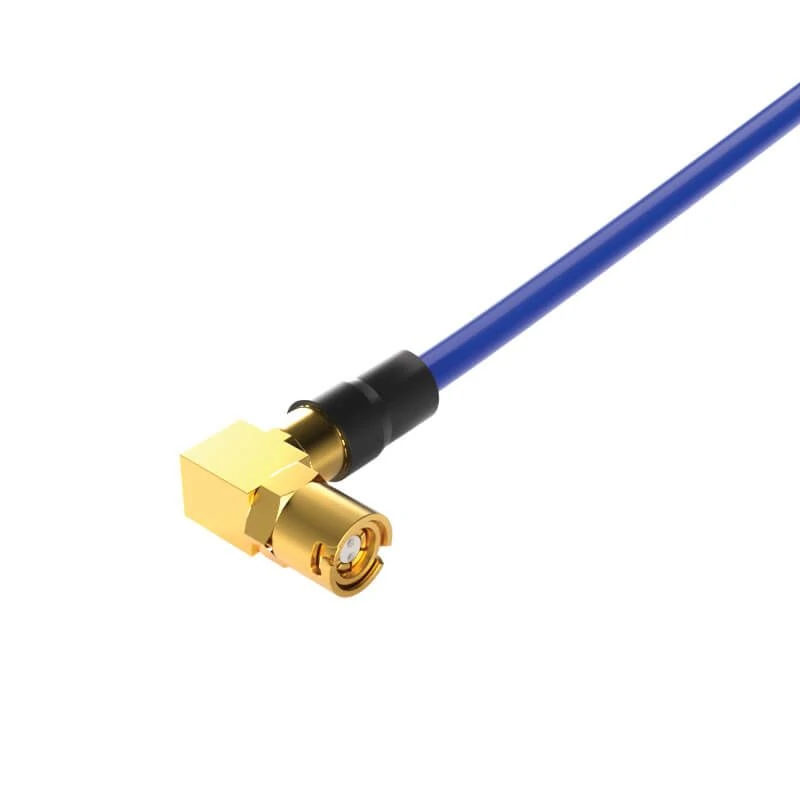
A low loss RF cable assembly with SMA right angle connector design, suitable for wireless devices, RF modules, communication equipment, and test systems requiring compact installation.
A standard coaxial cable may work well for short connections, but RF loss becomes harder to ignore as distance and frequency increase.
Every RF cable introduces attenuation. The signal entering one end of the cable will not have the same power when it reaches the other end. The amount of reduction depends on cable construction, conductor material, dielectric design, shielding structure, and operating frequency.
A low loss RF cable is designed to reduce this signal reduction. Compared with general coaxial cable options, it usually uses construction methods such as lower-loss dielectric materials, improved conductor design, or larger cable dimensions to reduce attenuation.
The practical difference appears in system design.
A short internal connection inside an RF module may not require an advanced low-loss cable. However, an outdoor antenna feeder, a long communication link, or a microwave test connection can quickly become limited by cable loss.
Explain why RF systems require lower attenuation cables
RF engineers normally look at attenuation using dB values.
A cable specified at 0.3 dB/m and another cable specified at 0.8 dB/m may appear close in a short assembly. At 10 meters, the difference becomes 5 dB. In an RF link, that difference can affect the available signal margin.
A simplified comparison:
| Cable Situation | Main Concern | Possible Result |
| Short internal jumper | Flexibility and routing | Standard flexible coax may be sufficient |
| Medium-length RF connection | Cable attenuation | Low loss cable improves link margin |
| Long antenna feeder | Total transmission loss | Lower attenuation becomes a priority |
| High-frequency test cable | Measurement accuracy | Stable RF characteristics are required |
A common sourcing mistake is selecting a cable only by diameter or price.
A thicker cable often has lower loss because the conductor size and dielectric structure can be improved, but that does not automatically make it suitable for every application. A large cable may create installation problems because of bending radius, connector availability, or mechanical stress. A cable that changes electrical characteristics after repeated bending may create unexpected variation during testing.
For microwave applications, the cable and connector combination must be considered together. A cable rated for a certain frequency does not guarantee the complete assembly will maintain the same performance after connector termination.
Compare low loss cables with standard coaxial cables
The difference between low loss coax cable and standard coaxial cable is not only the attenuation specification.
Engineers also need to consider impedance, shielding, flexibility, frequency capability, and connector compatibility.
Most RF systems use 50 ohm cable.
A cable with excellent attenuation characteristics can still create problems if the connector termination is incorrect or the assembly is not suitable for the operating frequency.
| Selection Item | Standard Coaxial Cable | Low Loss RF Cable |
| Attenuation | Higher loss per meter | Lower loss design |
| Long-distance transmission | More signal reduction | Better signal preservation |
| Cable size | Usually smaller and flexible | Often larger depending on construction |
| Frequency application | Depends on cable type | Designed for demanding RF ranges |
| Typical use | Internal wiring, short links | Antenna, communication, test applications |
The choice is not always “low loss is better”.
For example, a portable device may require a flexible cable with a small bend radius. A larger low-loss cable may provide better attenuation but create mechanical problems during installation.
The cable specification should follow the actual RF path requirement.
How Do You Evaluate RF Cable Loss Before Selecting a Cable?
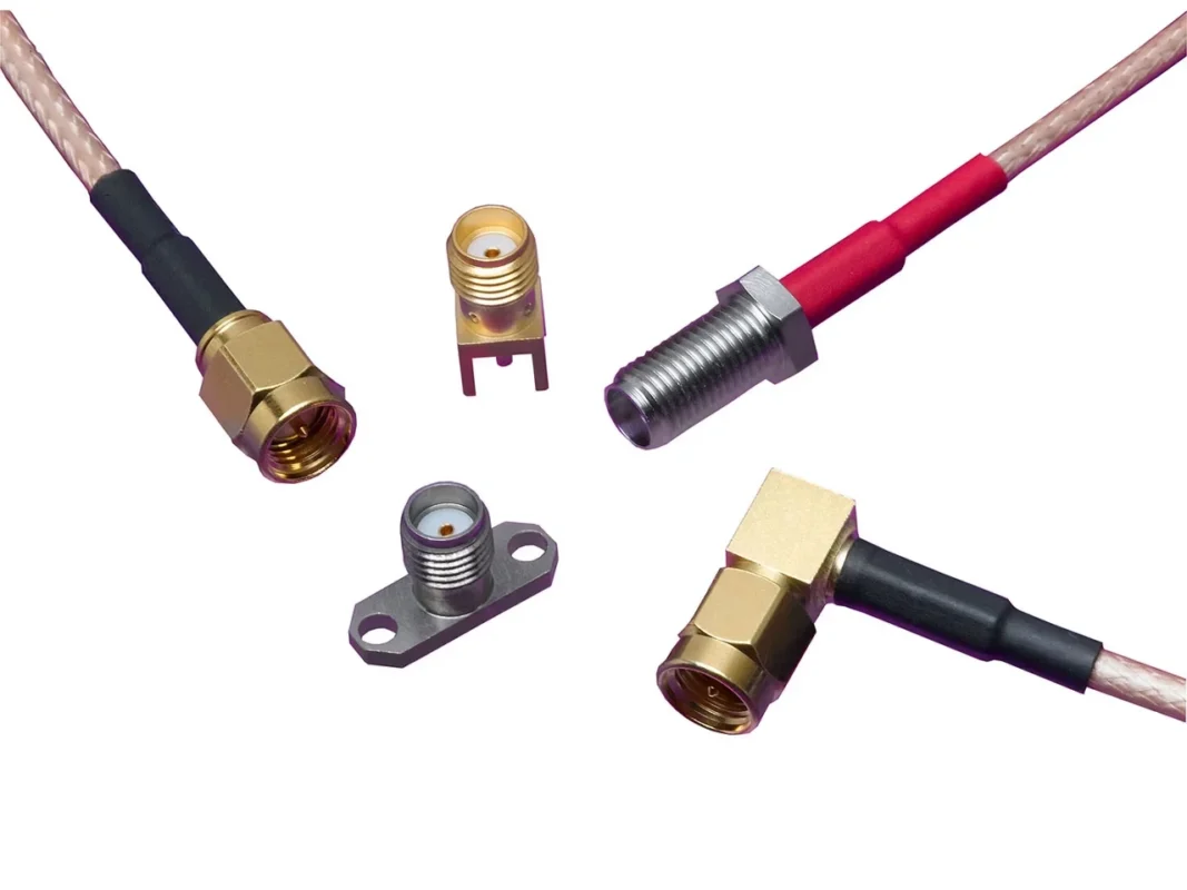
Many cable selections fail because the buyer checks only the product name.
A request such as “need low loss RF cable” is not enough for production.
The supplier usually needs additional information:
- Operating frequency
- Cable length
- Connector type
- Required impedance
- Installation environment
- Required test data
Without these details, two cables with similar appearance may perform differently in the final assembly.
Understand attenuation values at different frequencies
Cable attenuation is normally expressed in dB/m.
The same cable does not have identical loss across all frequencies. As frequency increases, conductor loss and dielectric loss generally increase.
A cable showing excellent results at 1 GHz may have very different performance near its upper frequency limit.
When comparing specifications, check:
- Attenuation value at the actual working frequency
- Maximum operating frequency
- Required cable length
- Connector transition loss
A practical example:
A 2-meter RF cable used at 900 MHz and the same cable used at 6 GHz are not facing the same design conditions. The higher-frequency application requires more attention to cable construction and connector rating.
For this reason, RF buyers should avoid selecting cables only by a general “low loss” description. The important question is whether the loss is acceptable at the actual operating point.
How Do You Calculate Total Loss Before Choosing a Low Loss RF Cable?
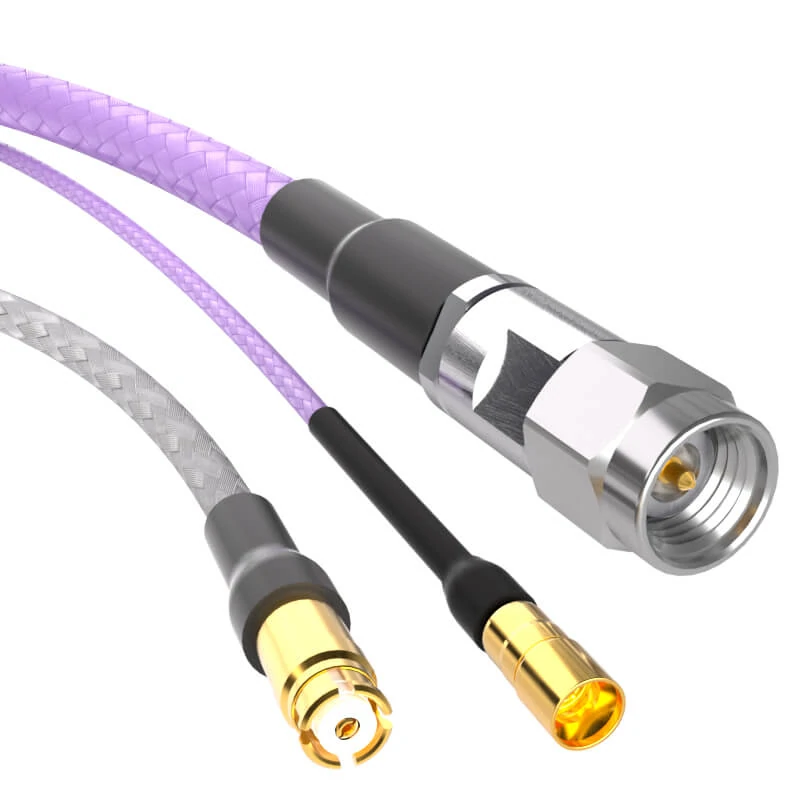
A low loss RF cable assembly featuring multiple connector interfaces designed for RF testing, microwave communication, and antenna connection applications. Proper cable and connector matching helps maintain signal integrity across different frequency ranges.
A cable specification sheet usually provides attenuation data, but the number on the datasheet is only one part of the RF path.
The actual signal loss in a working system is affected by several components:
- Cable attenuation
- Connector insertion loss
- Adapter transitions
- Cable length
- Installation conditions
A common mistake during procurement is comparing two cables only by their dB/m value while ignoring the complete assembly.
A lower-loss cable may not provide a meaningful improvement if the design uses multiple adapters or poorly matched connectors.
Calculate total cable loss based on length
The cable itself contributes approximately 1.25 dB loss.
However, the actual RF link loss is usually higher because the connection points also contribute loss.
This calculation becomes important in test systems and microwave applications where small differences can affect measurement accuracy.
This simple worksheet is useful during BOM review because it forces the buyer to consider the complete RF connection instead of only selecting a cable number.
Leave sufficient margin for real RF systems
Laboratory calculations are usually based on ideal conditions.
Production environments introduce additional variables:
- Connector tolerance
- Cable bending
- Temperature changes
- Assembly variation
- Repeated mating
A cable assembly that performs well when straight on a test bench may behave differently after installation.
This is especially common with compact equipment. The cable may be forced into a smaller routing path, creating mechanical stress near the connector termination area.
For demanding applications, engineers normally leave some performance margin.
A practical approach is to avoid selecting a cable that operates permanently at its maximum frequency or loss limit.
For example:
A cable assembly used at 5.8 GHz should not always be selected only because the specification reaches 6 GHz. A larger frequency margin can provide better tolerance against manufacturing variation.
How Should You Select Cable Construction for Low Loss RF Applications?
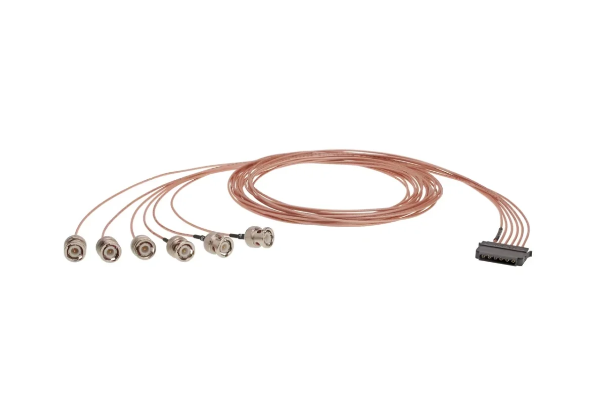
Low loss performance comes from cable construction, not only the product label.
Two cables may both be described as “low loss coax cable”, but their internal structures can be different.
Important construction factors include:
- Conductor material
- Dielectric material
- Shielding structure
- Cable diameter
- Mechanical flexibility
- Connector compatibility
The correct balance depends on where the cable will be installed.
Choose flexible cables for compact RF installations
Flexible RF cables are commonly used inside equipment where routing space is limited.
Typical applications include:
- Internal RF modules
- Wireless devices
- Communication equipment
- Portable test equipment
The advantage is easier installation.
However, flexible cables usually face a trade-off between size and attenuation.
A very small cable is convenient for assembly, but smaller conductors and dielectric structures may increase signal loss.
This is why compact RF designs often require a balance between:
- Cable diameter
- Minimum bend radius
- Frequency range
- Expected loss
A common sourcing issue is selecting a cable only because it physically fits the enclosure.
The cable may fit mechanically but fail to provide enough RF margin at the target frequency.
Choose low-loss coax cables for longer transmission distances
For longer connections, attenuation usually becomes the first consideration.
Applications include:
- Antenna feeder systems
- Outdoor communication links
- Fixed RF installations
Larger low-loss cables often reduce attenuation because they can use:
- Larger conductors
- Lower-loss dielectric materials
- Improved shielding structures
The trade-off is installation difficulty.
A larger cable may require:
- Larger connector bodies
- More installation space
- Greater bending radius
- Stronger mechanical support
Consider shielding and mechanical structure together
Low attenuation does not automatically mean a cable is suitable for industrial use.
In real installations, shielding and mechanical reliability are equally important.
Poor shielding may allow external interference into the RF path.
Mechanical problems can appear through:
- Excessive bending
- Pulling force
- Connector stress
- Repeated installation cycles
For example, an antenna cable installed outdoors may require additional protection compared with a short laboratory jumper.
How Does Frequency Range Affect Low Loss RF Cable Selection?
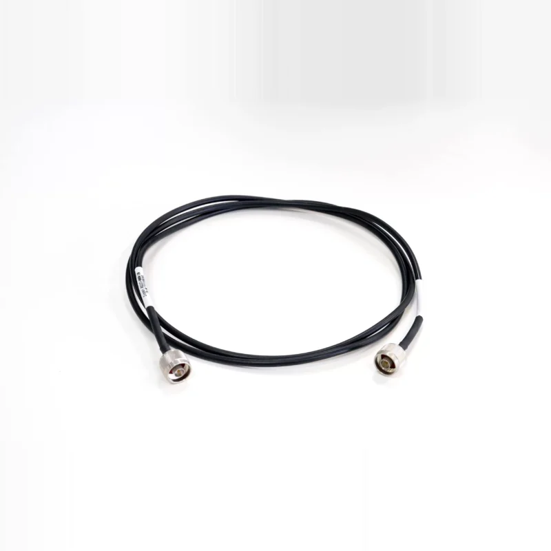
A cable that works at one frequency range may not provide the same result at a higher frequency.
RF buyers sometimes focus on the connector rating and overlook the cable itself.
The complete assembly frequency capability is limited by the weakest component:
- Cable
- Connector
- Adapter
- Termination process
A high-frequency connector attached to a lower-frequency cable does not automatically create a high-frequency assembly.
Match cable frequency rating with RF system requirements
Before selecting a low loss RF cable, confirm:
- Maximum operating frequency
- Required bandwidth
- Connector frequency rating
- Test requirement
For example:
A cable assembly using SMA connectors may be mechanically correct, but the actual performance depends on the cable type, connector design, and termination quality.
The SMA interface itself does not define the complete RF performance.
Select microwave cables for higher frequency applications
Microwave systems normally require tighter control of:
- Insertion loss
- VSWR
- Phase stability
- Mechanical consistency
Typical applications include:
- Microwave testing
- Precision measurement equipment
- RF laboratory systems
For these applications, cable assemblies are often tested after termination rather than relying only on component specifications.
A supplier may need to provide:
- VSWR data
- Insertion loss data
- Test frequency range
- Assembly inspection records
Avoid selecting cables only by attenuation values
Low attenuation is important, but it is not the only selection factor.
A cable with lower loss may still be unsuitable because:
- It cannot meet the required bend radius
- The connector is not compatible
- The assembly cannot withstand installation conditions
- The frequency margin is too small
A practical RF selection process considers:
- Operating frequency
- Required cable length
- Loss budget
- Connector matching
- Mechanical environment
- Testing requirements
Why Can a Good Low Loss RF Cable Still Fail After Connector Assembly?
A common mistake in RF sourcing is evaluating the cable and connector separately.
The cable datasheet looks acceptable. The connector frequency rating is higher than the application requirement. The first prototype passes basic testing.
Then the production batch shows unstable results.
The reason is that an RF cable assembly is not a collection of independent parts. The cable, connector, and termination process become one electrical structure.
A low loss coax cable only achieves its expected performance when the transition between cable and connector is properly controlled.
This is especially noticeable at higher frequencies.
At lower frequencies, small mechanical differences may have little effect. As frequency increases, small changes around the connector interface can introduce additional reflection and insertion loss.
Match connector design with cable construction before ordering
The connector interface is only one part of the selection.
For an RF cable assembly, buyers should also confirm:
- Cable diameter
- Dielectric structure
- Center conductor size
- Shielding method
- Termination process
A common purchasing error is ordering by connector name only.
For example:
“SMA male cable”
This description is incomplete.
An SMA connector used with RG316 cable and an SMA connector used with RG58 cable may have the same mating interface, but the internal structure is different.
The rear body, ferrule size, and contact design must match the cable.
Otherwise, problems may appear during:
- Pull force testing
- Vibration testing
- Repeated mating
- High-frequency measurement
A cable assembly can look perfect externally and still have unstable RF performance.
Connector transitions become more important at higher frequencies
Every connection point creates a possible RF discontinuity.
A simple RF path may include:
Radio module → Cable → Connector → Adapter → Antenna
Each additional transition increases the chance of:
- Impedance variation
- Reflection
- Additional insertion loss
This does not mean adapters should never be used.
In practical systems, adapters are often necessary because equipment uses different interfaces.
The important point is to include them in the RF design.
A laboratory setup with several adapters may show different measurement results compared with a direct cable connection.
For test applications, engineers usually pay more attention to:
- Stable VSWR
- Repeatable insertion loss
- Phase consistency
because measurement error can be mistaken for device performance change.
Use complete cable assembly specifications in purchasing documents
Many RF procurement problems happen because the request information is incomplete.
A supplier receiving:
“Need low loss SMA cable, 1 meter”
still needs to ask several questions.
A better specification should include:
| Specification | Example |
| Connector A | SMA Male |
| Connector B | SMA Female |
| Cable Type | Low loss coax |
| Impedance | 50Ω |
| Length | 1000 mm |
| Frequency Range | DC–6 GHz |
| Application | Antenna / Test / Module |
| Required Test | VSWR or insertion loss |
This information avoids incorrect substitutions.
Two assemblies can have the same connector combination but completely different RF characteristics.
How Are Low Loss RF Cable Assemblies Tested Before Delivery?
Production testing depends on the application.
Not every cable requires the same inspection level.
A short internal jumper inside a consumer device and a microwave test cable should not follow the same acceptance standard.
The inspection method should match the risk.
Continuity testing is only the first step
Continuity testing confirms that the electrical path is connected.
It can detect:
- Open circuit
- Short circuit
- Basic assembly mistakes
But it cannot confirm RF behavior.
RF testing checks the actual transmission behavior
Insertion loss measurement
Used to check how much signal power is lost through the assembly.
Return loss measurement
Used to evaluate reflected signal performance.
For higher-frequency cable assemblies, suppliers may use a VNA to verify performance across the required frequency range.
A practical production issue is that testing only one sample does not always represent the complete batch.
For customized cable assemblies, process control is equally important:
- Cable preparation method
- Crimp tooling condition
- Operator training
- Inspection frequency
These factors influence consistency.
Low Loss RF Cable Acceptance Checklist
The following checklist can help buyers communicate requirements with suppliers:
| Check Item | Why It Matters |
| Cable model | Prevent wrong cable substitution |
| Cable length | Affects total attenuation |
| Connector type | Ensures correct mating interface |
| Impedance | Maintains RF matching |
| Frequency range | Confirms application suitability |
| Termination method | Influences repeatability |
| VSWR data | Required for sensitive RF systems |
| Insertion loss data | Confirms signal loss |
| Appearance inspection | Prevents mechanical damage |
The goal is not to test everything on every project.
The goal is to define the right inspection level before production begins.
Should You Buy Low Loss Cable or a Finished RF Cable Assembly?
This decision usually depends on where the termination work happens.
Some companies prefer raw cable because they already have internal assembly capability.
Others choose finished assemblies because they want consistent production results.
Neither approach fits every project.
Raw cable is suitable when internal processing is available
Raw cable is commonly selected for:
- OEM production
- Large-volume manufacturing
- Custom connector development
The advantage is flexibility.
The engineering team can choose different connectors during product development.
Cable assemblies reduce production uncertainty
A finished RF cable assembly is often preferred when the buyer needs:
- Fixed length
- Defined connector combination
- Faster integration
- Stable repeatability
This is common for:
- RF test equipment
- Communication systems
- Antenna connections
- Prototype-to-production transition
The supplier manages the termination process, which reduces one source of variation.
Make the decision based on production reality
The important question is not which option is cheaper.
The better question is where the technical risk should be controlled.
FAQ
Why does a low loss RF cable sometimes show higher loss than expected?
The cable specification may only represent the cable itself. The complete assembly also includes connector transitions, termination quality, adapters, and installation conditions. Testing the finished assembly provides a more realistic result.
Can any SMA connector be used with a low loss coax cable?
No. SMA is only the interface type. The connector body and termination structure must match the actual cable diameter and construction.
Why can a low loss RF cable have higher measured loss after assembly?
A low loss RF cable specification usually describes the cable performance only. The final RF assembly also depends on connector selection, termination quality, adapter quantity, and installation conditions. A cable that performs well before assembly may show different results after connectors are installed, especially at higher frequencies where small impedance changes can increase insertion loss or reflection.
Is a low loss RF cable always the best choice for a short RF connection?
Not always. For a short jumper inside equipment, installation space and flexibility may be more important than achieving the lowest possible attenuation. A larger low-loss cable may reduce signal loss, but it can also create problems with bending radius, routing space, or connector selection. The cable should match the actual installation condition.
Why does the RF cable performance change after replacing the connector?
The cable itself may not be the problem. During connector replacement, the termination area becomes part of the RF path. A small difference in stripping length, shielding contact, or center pin alignment can affect impedance matching. This is why two assemblies using the same cable and connector model can sometimes show different VSWR or insertion loss results after production.
