
A splitter can look correct, pass a continuity check, and still fail theRF system.
This happens more often than many buyers expect.
The connector type matches the drawing. The housing looks normal. The signal appears at every output port. During a quick bench test, there may be no obvious problem.
The issue usually appears when the system moves closer to the actual operating condition.
A 2.4 GHz antenna test system may show uneven output levels. A microwave measurement setup may have unexpected loss. A multi-channel communication device may experience different signal levels between branches.
The reason is simple: an RF power splitter is not just a mechanical adapter with several ports. The internal circuit determines how power is divided, how much energy is lost, and how much interaction exists between output channels.
How Does a Power Splitter Divide RF Signals Without Damaging the System?
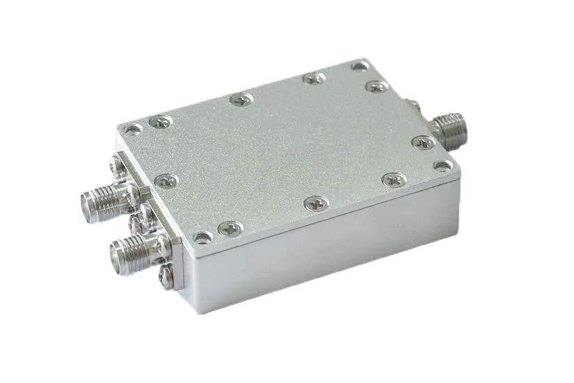
This metal-housed SMA RF power splitter supports RF signal distribution where stable insertion loss, impedance matching, and port isolation are important. It is suitable for RF laboratories, communication devices, antenna distribution networks, and production test fixtures.
In many RF designs, one signal source needs to serve multiple paths.
A single RF generator may need to connect to several test channels. One antenna feed may need to distribute signals to multiple modules. A communication system may require the same input signal to reach different receiver paths.
This is where a power splitter is used.
This is why a common mistake in RF system design is selecting the number of outputs first and checking the power budget later.
The correct order is usually the opposite:
- Confirm required output paths.
- Calculate available power after splitting.
- Check whether each connected device still receives enough signal level.
- Verify the splitter specifications at the operating frequency.
A splitter that works well in a low-power test setup may not be suitable when the same design moves into a production environment.
What Is the Difference Between a Power Splitter, RF Coupler, and Switch?
These components are often placed together in RF system diagrams, but they solve different problems.
A power splitter distributes a signal.
An RF coupler samples a signal.
An RF switch changes the connection path.
The difference becomes important during system design.
| Component | Main Purpose | Typical Use |
| Power Splitter | Divide one signal into multiple outputs | Antenna distribution, RF testing |
| RF Coupler | Extract part of RF energy | Monitoring and measurement |
| RF Switch | Select different signal routes | Switching networks |
| Attenuator | Reduce signal level | Power control |
For example, a test engineer checking transmitter output may not need the entire RF signal. A directional coupler can provide a smaller sample for measurement while keeping the main path active.
A production test fixture feeding several identical devices usually needs a power splitter instead.
Choosing the wrong component may not create an immediate failure. The system may simply show inconsistent measurement results or unexpected signal levels.
That is why the application goal should be confirmed before selecting the part number.
Why Does a Power Splitter Always Have Some Signal Loss?
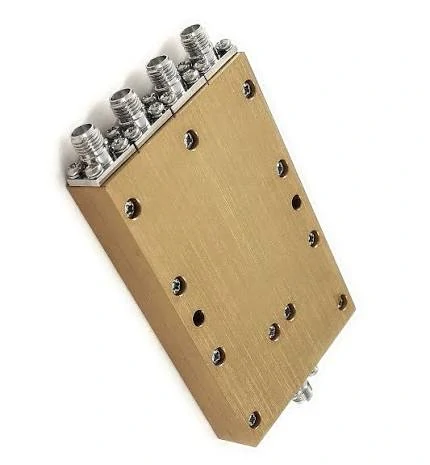
This SMA RF power splitter is designed for signal distribution in RF testing, antenna systems, communication equipment, and multi-channel measurement setups. It helps engineers divide one input signal into multiple controlled output paths while considering insertion loss, isolation, and frequency range.
A buyer looking at a splitter datasheet may notice that the insertion loss is higher than expected.
For example, a 2-way splitter may show around 3.2 dB loss instead of the theoretical 3.01 dB.
This does not necessarily mean the product has poor performance.
The extra loss comes from the physical RF structure.
Real components include:
- conductor resistance
- dielectric loss
- internal matching network loss
- connector transition loss
- impedance mismatch effects
The theoretical splitting loss only describes the ideal power division.
Actual RF performance includes the losses created by the component itself.
A practical RF engineer normally separates these two values:
Splitting loss
The unavoidable loss caused by dividing power.
Insertion loss
Additional loss caused by the actual device structure.
Which Specifications Matter Besides Insertion Loss?
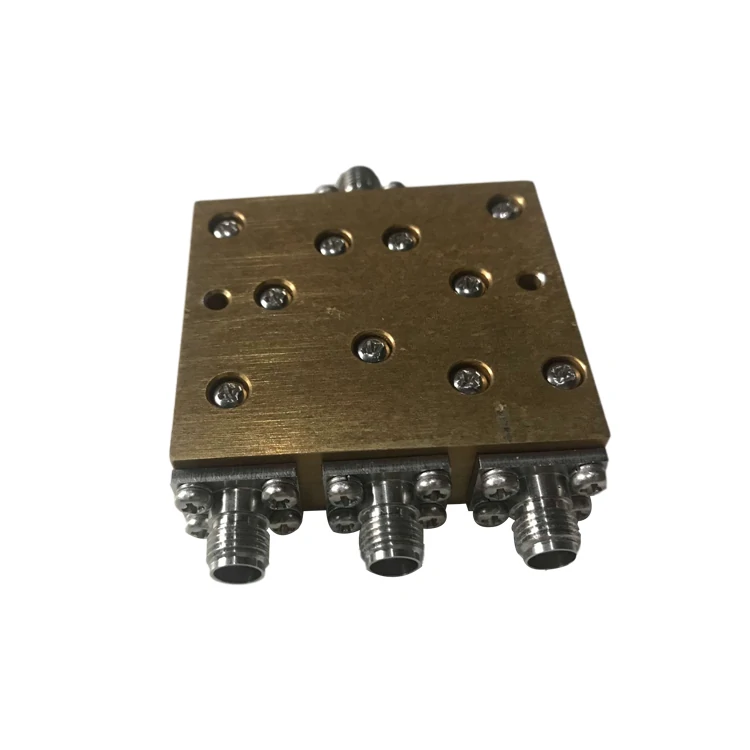
This SMA power splitter is designed for RF signal distribution in test equipment, communication systems, and antenna-related applications. Before selection, engineers should confirm operating frequency, impedance, connector type, insertion loss, isolation, and required output power.
Insertion loss is usually the first number buyers check.
It should not be the only number.
Two splitters may have similar insertion loss but behave differently in a real system.
Important parameters include:
| Parameter | Why It Matters |
| Isolation | Reduces signal interaction between output ports |
| Return Loss | Shows impedance matching quality |
| VSWR | Indicates reflected signal level |
| Amplitude Balance | Checks output power difference |
| Phase Balance | Important for phased-array and measurement systems |
| Frequency Range | Determines whether the splitter fits the application |
Isolation is especially important when multiple devices are connected at the same time.
Without enough isolation, a signal from one output path can affect another path.
This may not be obvious during basic testing but can become a problem in:
- multi-channel receivers
- RF calibration systems
- antenna arrays
- microwave measurement setups
RF Power Splitter Loss Calculation Tool for System Planning
Before selecting a splitter, engineers can estimate the expected output level using a simple calculation.
Required Inputs
| Parameter | Example |
| Input Power | 20 dBm |
| Output Count | 2 / 4 / 8 ports |
| Insertion Loss | 0.5 dB |
| Frequency | 6 GHz |
| Impedance | 50Ω |
Calculation Formula
Theoretical splitting loss:
Ls = 10log10(N)
Where:
N = number of output ports
Estimated output power:
Pout = Pin – Ls – Li
Where:
Pin = input power
Ls = splitting loss
Li = insertion loss
This calculation provides:
- expected output power per port
- available RF margin
- whether the splitter configuration is suitable
For procurement teams, this information is useful before requesting samples because it helps avoid selecting a component that looks correct but cannot meet the system requirement.
A splitter should fit the entire RF path.
The cable length, connector quantity, operating frequency, and receiver sensitivity all influence the final result.
Which Power Splitter Configuration Matches Your RF Application?
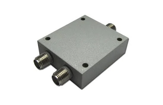
This 2-way SMA RF power splitter is suitable for basic signal branching, RF measurement, antenna testing, and prototype development. It helps split one input signal into two output ports while the system designer checks splitting loss, insertion loss, and impedance matching.
The number of output ports is usually the first thing buyers notice when selecting a power splitter.
It is also one of the easiest places to make a wrong decision.
A 2-way splitter, 4-way splitter, and 8-way splitter may look similar from the outside, but the difference appears immediately in the RF power budget.
More outputs mean more signal paths.
They also mean more splitting loss.
A design that works well with a 2-way splitter may lose too much signal margin after changing to an 8-way version.
The right question is not:
“How many ports can the splitter provide?”
The better question is:
“How much signal level does each output need after the split?”
Why Is a 2-Way Splitter the Most Common Choice?

A 2-way splitter is widely used because it provides a simple balance between signal distribution and power loss.
Typical applications include:
- antenna signal branching
- RF laboratory testing
- communication equipment
- prototype development
- production test fixtures
In many systems, two output paths are enough.
For example, during RF testing, an engineer may need the same source signal connected to a reference channel and a measurement channel.
A 2-way splitter allows both paths to receive the same input signal without repeatedly reconnecting cables.
However, the available power should be checked before installation.
A transmitter output of 10 dBm does not become 10 dBm at both outputs.
After an ideal 2-way split:
Input:
10 dBm
Splitting loss:
3.01 dB
Each output:
Approximately 6.99 dBm
If the connected device requires a higher signal level, the system may need additional gain or a different distribution method.
This is a common issue when a splitter is added late in a project.
The mechanical installation is simple, but the RF budget changes.
When Should You Use a 4-Way or 8-Way Splitter?
Multi-output splitters are useful when one RF source needs to feed several channels.
Typical applications include:
- multi-channel test systems
- antenna distribution networks
- communication platforms
- RF production testing
The advantage is clear:
One signal source can support multiple devices.
The limitation is also clear:
Every additional output reduces available power.
| Splitter Type | Ideal Division Loss | Common Application |
| 2-Way | 3.01 dB | Basic RF distribution |
| 3-Way | 4.77 dB | Small multi-channel systems |
| 4-Way | 6.02 dB | Test systems and RF networks |
| 8-Way | 9.03 dB | Large signal distribution |
A common purchasing mistake is selecting a higher port-count splitter because it provides more flexibility.
The unused ports still affect the design.
The system must consider:
- output power requirement
- frequency range
- isolation requirement
- connected equipment sensitivity
For example, an 8-way splitter may be suitable for a production test rack where the input signal is strong enough.
The same splitter may not be suitable for a low-power receiver system where every dB matters.
Why Are Wilkinson Splitters Common in RF Systems?
Not all splitters use the same internal structure.
One widely used design is the Wilkinson power splitter.
The reason engineers choose this structure is not simply because it divides signals.
The key advantage is the isolation between output ports.
The design still needs to match:
- frequency range
- power handling
- physical size
- cost requirement
- connector configuration
For a simple low-frequency distribution task, a different splitter structure may already meet the requirement.
For microwave applications, internal design details become much more important.
Why Does Impedance Matching Matter When Selecting a Splitter?
An RF splitter does not work independently.
It connects to cables, connectors, antennas, and electronic equipment.
All parts need to operate in the same impedance environment.
Most RF communication and test systems use:
50Ω impedance
A mismatch can create reflected energy.
The result may include:
- higher VSWR
- increased insertion loss
- unstable measurement results
- reduced system efficiency
The problem is that a mismatch may not be obvious.
The connector can physically fit.
The signal may still pass.
A basic continuity test may also show no issue.
But at RF frequencies, the electrical behavior can be different.
This is why buyers should confirm impedance before selecting a splitter.
| Item | Confirm Before Ordering |
| System impedance | 50Ω or 75Ω |
| Frequency range | Actual operating frequency |
| Connector interface | SMA, N, BNC, TNC, etc. |
| Application | Testing, antenna, communication |
A 50Ω splitter should not be treated as interchangeable with a 75Ω component simply because the connectors appear similar.
Do Connector Types Affect Power Splitter Performance?
The connector is not the only factor determining RF performance, but it does affect the complete signal path.
Common power splitter interfaces include:
- SMA
- N-Type
- BNC
- TNC
Each connector has different mechanical dimensions and frequency capabilities.
For example:
An SMA splitter may be suitable for compact microwave test systems.
An N-Type splitter may be preferred for applications requiring stronger mechanical durability or outdoor installation.
A BNC splitter may be common in lower-frequency equipment.
The selection should match the surrounding equipment.
Adding adapters is sometimes necessary, but every additional connection introduces another transition point.
Possible effects include:
- additional insertion loss
- mechanical tolerance issues
- more opportunities for impedance discontinuity
In a low-frequency application, one adapter may have little impact.
In a microwave measurement setup, several adapters in series can affect the test result.
Why Does Frequency Range Matter More Than Connector Appearance?
A common sourcing misunderstanding is:
“The splitter uses SMA connectors, so it should support my SMA system.”
This assumption is incorrect.
The connector only describes the interface.
The internal RF structure determines the usable frequency range.
For example, SMA-based splitters may be designed for:
- DC-3 GHz
- DC-6 GHz
- DC-18 GHz
- microwave applications above this range
The difference comes from:
- internal conductor design
- dielectric material
- machining accuracy
- matching structure
A splitter rated for 3 GHz may physically connect to a 10 GHz system.
It does not mean the RF performance will be acceptable.
At higher frequencies, small mechanical differences become electrical problems.
How Should Engineers Evaluate Splitter Performance Across Frequency?
A splitter specification should be reviewed at the actual operating frequency.
A component that performs well at 1 GHz may behave differently near its upper limit.
Phase Balance
Important for systems where multiple signals must maintain a controlled phase relationship.
For general RF distribution, amplitude balance may be enough.
For phased-array or precision measurement systems, phase balance becomes a key specification.
The splitter should be evaluated based on the actual RF requirement, not only the product name.
When Should You Choose a Power Splitter Instead of a Coupler?
During RF system design, engineers sometimes confuse power splitters and directional couplers because both components have multiple ports.
The difference becomes clear when looking at the purpose of each RF path.
A splitter is used when the signal needs to be distributed.
A coupler is used when part of the signal needs to be monitored or sampled.
The two components may appear similar in a schematic, but they solve different engineering problems.
A power splitter normally has:
- one input port
- multiple output ports
- relatively balanced output paths
A directional coupler normally has:
- input port
- output port
- coupled port for measurement
The selection depends on what happens after the signal leaves the component.
Use a Splitter When Multiple Devices Need the Same RF Source
A power splitter is suitable when one RF source needs to feed several destinations.
Typical applications include:
- antenna distribution
- multi-channel testing
- communication equipment
- RF development platforms
For example, a production test system may use one signal generator to test several RF modules.
The goal is not to measure a small part of the signal.
The goal is to provide multiple controlled signal paths.
In this situation, the important parameters are usually:
- output count
- insertion loss
- output balance
- isolation
- frequency range
Use a Coupler When the System Needs Signal Monitoring
A directional coupler is commonly used when engineers need access to a portion of the RF signal without interrupting the main path.
Typical applications include:
- transmitter monitoring
- power measurement
- calibration systems
- feedback circuits
For example, an engineer may need to check transmitted power during operation.
A coupler can provide a measurement port while allowing the main RF signal to continue.
The selection logic is simple:
| System Requirement | Suitable Component |
| Split one signal into equal paths | Power Splitter |
| Monitor RF power | Directional Coupler |
| Create multiple test outputs | Power Splitter |
| Sample a small RF portion | Directional Coupler |
Using a coupler instead of a splitter may still allow the system to pass a basic test, but the output power relationship will not match the original design.
What Information Should Be Confirmed Before Ordering a Power Splitter?
Many RF sourcing problems start with incomplete specifications.
A request such as:
“Need SMA power splitter”
does not provide enough information for accurate production.
The supplier still needs to know what the splitter will do inside the system.
At minimum, confirm:
- operating frequency
- impedance
- split ratio
- connector type
- power requirement
- application environment
A splitter for laboratory measurement and a splitter installed inside communication equipment may have completely different requirements.
The same connector does not mean the same product.
RF Power Splitter Specification Checklist
Before requesting a quotation, prepare the key parameters.
| Parameter | Example Requirement |
| Split Ratio | 1:2 / 1:4 / 1:8 |
| Frequency Range | DC-6 GHz |
| Impedance | 50Ω |
| Connector Type | SMA |
| Insertion Loss | Required dB value |
| Isolation | Required separation between outputs |
| Power Handling | Maximum input power |
| Application | Testing / Communication / Antenna |
A clear specification reduces unnecessary communication and avoids incorrect substitutions.
For example, the following description provides much more useful information:
2-way SMA 50Ω power splitter, DC-6GHz, low insertion loss, high isolation for RF testing.
Compared with:
SMA splitter
the second description leaves many important details undefined.
Why Should Buyers Consider the Complete RF Path Instead of Only the Splitter?
The splitter is only one part of the RF chain.
The final system performance also depends on:
- cable type
- cable length
- connector quantity
- adapter quantity
- antenna characteristics
- equipment input matching
A splitter may meet the datasheet specification and still create problems after installation.
For example:
A system originally tested with a short cable may show different results after the production version uses a longer cable assembly.
The additional cable loss and connector transitions change the total RF budget.
This is why experienced RF teams evaluate the complete assembly rather than reviewing one component independently.
How Can You Test a Power Splitter Before Production Use?
A power splitter should be verified before it becomes part of a larger RF system.
Visual inspection is useful.
Mechanical inspection is useful.
Continuity testing is useful.
However, these checks do not confirm RF performance.
A multimeter can verify whether the circuit is connected.
It cannot determine:
- insertion loss
- isolation
- VSWR
- frequency response
- phase balance
For these measurements, RF engineers normally use a Vector Network Analyzer (VNA).
Which Measurements Should Be Included in Splitter Testing?
A basic RF acceptance test usually includes several measurements.
Power Splitter Acceptance Test Record
For supplier approval or incoming inspection, a practical record may include:
| Test Item | Record |
| Model Number | Product identification |
| Frequency Range | Tested frequency band |
| Input Connector | Interface type |
| Output Connector | Interface type |
| Impedance | 50Ω / 75Ω |
| Insertion Loss | Measured value |
| Isolation | Output separation |
| VSWR | Return performance |
| Amplitude Balance | Port difference |
| Result | Pass / Fail |
Maintaining test records is useful for repeated purchasing.
If a later production batch shows different behavior, previous records provide a reference point.
FAQ
Why does a 2-way splitter usually lose about 3 dB?
Because the input power is divided into two equal outputs.
The theoretical calculation is:
10log10(2) = 3.01 dB
Actual measured loss is usually slightly higher because of internal component loss and impedance effects.
Can a power splitter work as a signal combiner?
Some passive RF networks may operate in reverse.
However, the result depends on:
- frequency range
- isolation
- power level
- internal design
A splitter should only be used as a combiner when the manufacturer specification supports that application.
Can continuity testing confirm a power splitter is good?
No.
Continuity only confirms electrical connection.
It does not verify RF characteristics.
A splitter can pass continuity and still fail insertion loss, VSWR, or isolation requirements.
Why does my 2-way power splitter show more than 3 dB loss?
A 2-way power splitter should have about 3.01 dB of ideal splitting loss because the input power is divided into two paths. In real parts, the measured value is usually a little higher. The extra loss may come from conductor resistance, dielectric loss, connector transitions, internal matching structure, or mismatch in the connected RF path. A reading around 3.2 dB is not automatically a problem, but it should be checked against the specified frequency and test method.
Can I choose a power splitter only by connector type?
No. Connector type is only the mechanical interface. An SMA power splitter, for example, may support DC-3 GHz, DC-6 GHz, DC-18 GHz, or a different range depending on the internal design. The same connector shape does not prove the same RF performance. Before ordering, check frequency range, impedance, split ratio, insertion loss, isolation, and power handling. This matters even more when the system is working near the upper frequency limit.
Final Selection Notes for RF Buyers
A suitable power splitter is determined by the system requirement, not only the connector type or port number.
Before placing an order, confirm:
- frequency range
- impedance
- split ratio
- connector interface
- insertion loss target
- isolation requirement
- power handling
- inspection method
For applications near the upper frequency limit, provide the complete RF conditions before selecting the component.
The operating frequency, cable assembly, connector count, and expected test method often determine whether a standard splitter is sufficient or whether a customized design is needed.
