
A cable can pass continuity testing and still be the wrong RF connection.
This often happens when an engineer replaces an existing connector interface with an adapter without checking the complete signal path. The threads match, the parts screw together, and the system appears to work at low frequency. The problem shows up later during antenna tuning, VNA measurement, or field installation when return loss increases or the RF link becomes unstable.
A typical example is an antenna system using an N-type interface that needs to connect with a smaller SMA test port. The mechanical conversion is simple: add an N to SMA adapter. However, the adapter must still match the impedance, frequency range, connector gender, and application environment. A 50Ω adapter used in a controlled RF test setup is a different requirement from an outdoor antenna installation exposed to vibration and weather.
This is why N Type adapters are not selected only by connector name. The correct choice depends on the complete RF path.
How Do N Type Adapters Enable RF Interface Conversion?
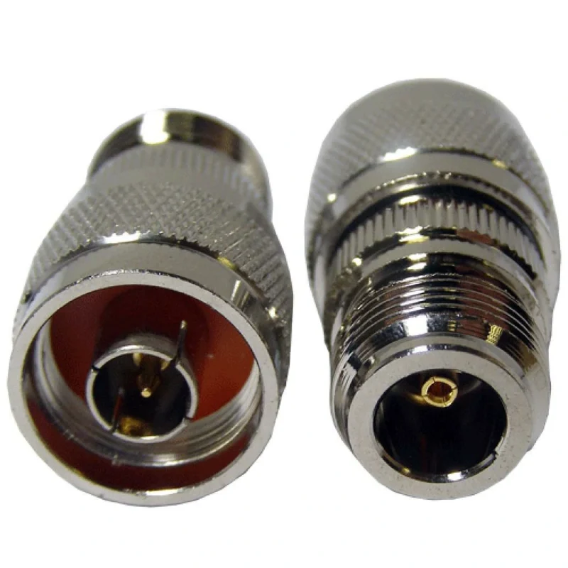
An N Type adapter is used when two RF components use different connector interfaces but must remain electrically connected. In practical RF systems, it acts as a mechanical and electrical bridge between equipment ports, cable assemblies, antennas, and test instruments.An N Type to SMA adapter provides the conversion path without requiring a new cable assembly.
However, the adapter becomes part of the RF transmission path. Its electrical characteristics affect the entire connection.
Important parameters include:
| Parameter | Why It Matters |
| Connector interface | Determines whether the adapter physically mates with the equipment |
| Gender | Prevents incorrect male-to-male or female-to-female connections |
| Impedance | Most RF systems require 50Ω matching |
| Frequency range | Ensures the adapter works within the operating band |
| VSWR / return loss | Indicates signal reflection caused by mismatch |
| Mechanical structure | Affects durability and installation reliability |
A common sourcing mistake is selecting an adapter only by appearance. Two N adapters may look almost identical externally while having different frequency ratings, internal structures, or impedance characteristics.
For RF engineers and procurement teams, the adapter specification should always describe both sides of the conversion.
A better requirement:
N male to SMA female adapter, 50Ω, DC–6 GHz, used for RF antenna measurement.
A weak requirement:
N connector adapter.
The second description does not define the connection direction, electrical requirement, or intended application.
Why Is an Adapter Different From Replacing the Connector?
An adapter is normally chosen when the existing RF components are already fixed.
Typical situations include:
- connecting legacy equipment with new RF modules
- temporary laboratory configurations
- prototype testing
- antenna measurement setups
- production debugging
Replacing the connector or rebuilding the cable assembly may be unnecessary if the mechanical interface is the only difference.
However, adapters also introduce another RF transition.
The decision is usually based on application requirements:
| Situation | Recommended Choice | Reason |
| Laboratory testing | N Type adapter | Fast interface conversion |
| Prototype development | Adapter | Easy configuration changes |
| Outdoor antenna installation | Cable assembly | Better environmental reliability |
| Production equipment | Cable assembly | Fewer connection points |
| Temporary RF measurement | Adapter | Reusable between setups |
The key point is that an adapter solves a connection problem. It does not automatically solve an RF design problem.
How Do You Choose the Correct N Type Adapter Direction?
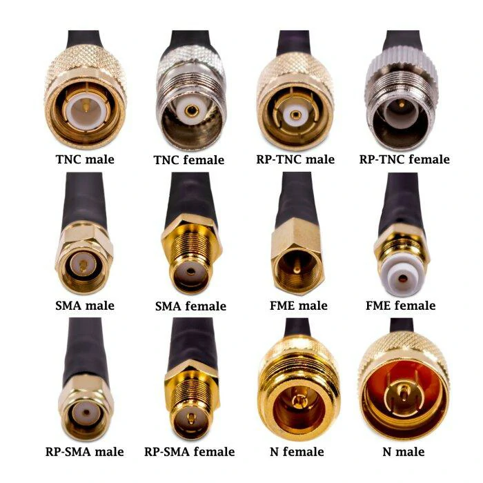
This image shows different RF connector families including SMA, TNC, BNC, and N Type connectors. Each connector has different mechanical structures, coupling methods, and application environments. Choosing the correct RF connector helps improve signal reliability and system compatibility.
Many adapter failures start with a simple mistake: the interface direction is wrong.
“N Type adapter” is only the connector family. It does not tell you whether the adapter connects an N male port to an SMA female port, or the opposite direction.
Before ordering, confirm:
- input connector type
- output connector type
- male or female interface
- cable side or equipment side
- mounting requirement
For example:
An antenna cable with an N female connector cannot directly connect to another N female port. The adapter must provide the correct male interface.
Typical conversion examples:
| Existing Connection | Required Adapter |
| N equipment port → SMA cable | N to SMA adapter |
| SMA device → N antenna cable | SMA to N adapter |
| N test port → BNC cable | N to BNC adapter |
| N antenna system → TNC equipment | N to TNC adapter |
Match N Male and N Female Interfaces Before Ordering
N Type connectors are widely used in antenna and communication systems because of their mechanical strength and 50Ω RF characteristics. But the connector family alone is not enough.
A complete adapter selection requires checking both sides.
The same connector family can have different mounting styles:
- cable mount
- panel mount
- bulkhead mount
- test adapter style
The mechanical installation method affects whether the adapter can be securely installed and whether additional sealing is required.
Avoid Selecting Adapters Only by Connector Name
Searching only for “N adapter” often creates unnecessary mistakes.
A buyer may receive a physically compatible part but discover later that:
- the frequency rating is too low
- the adapter uses the wrong gender
- the impedance does not match
- the mounting structure is unsuitable
- the connector transition adds unnecessary loss
For RF systems operating near the upper frequency range, the adapter should be treated as a controlled component in the signal chain rather than a simple mechanical accessory.
N Type Adapter Direction Selection Matrix
| Application Condition | Recommended Selection | Check Before Purchase |
| N equipment port to SMA test cable | N to SMA adapter | N gender + SMA gender |
| SMA module to N antenna cable | SMA to N adapter | Cable side interface |
| N measurement port to BNC instrument | N to BNC adapter | Impedance and frequency |
| N antenna system to TNC device | N to TNC adapter | Thread compatibility |
| Unknown RF interface | Confirm connector details first | Interface, gender, frequency |
The fastest way to avoid adapter selection errors is to define the RF path first:
Equipment port → Adapter interface → Cable interface → Operating frequency
This simple check prevents most ordering mistakes before they become installation problems.
How Do N Type Adapters Support SMA, BNC, and TNC Conversion?
Many RF systems are built from components that were never designed to work together.
A test engineer may have an N-type antenna port, an SMA measurement cable, and a BNC instrument available on the bench. The adapter is the small component that connects these different interfaces, but the selection mistake usually happens before the adapter is installed.
The connector family is only the starting point.
The engineer still needs to confirm:
- Is the system 50Ω?
- What frequency range will be used?
- Is this a test connection or a permanent installation?
- Does the adapter need to handle repeated mating?
A small adapter used between an antenna and a VNA is not selected in the same way as one installed inside a communication cabinet.
How Can You Match N Type and SMA Interfaces Correctly?
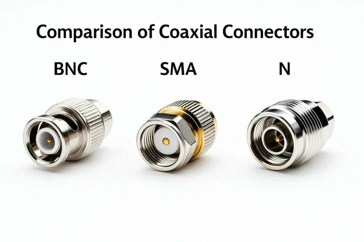
The N Type to SMAadapter is one of the most common RF conversions because the two connector families often appear in different parts of the same system.
N Type connectors are frequently found on:
- outdoor antennas
- wireless communication equipment
- power amplifiers
- larger coaxial cable assemblies
SMA connectors are more common on:
- RF modules
- compact test fixtures
- PCB-based equipment
- laboratory cables
The mechanical connection is straightforward. The engineering concern is whether the transition affects the RF path.
For example, a customer may request:
“Need an N adapter to connect our antenna to the SMA port.”
That information is incomplete.
The supplier still needs to know:
- N male or N female?
- SMA male or SMA female?
- Cable side or equipment side?
- Operating frequency?
- Required VSWR?
A better specification would be:
N female to SMA male adapter, 50Ω, DC–6 GHz, for antenna measurement.
That description allows the supplier to select the correct structure.
| Conversion Requirement | Common Adapter Choice | Confirm Before Ordering |
| Antenna N port to SMA device | N to SMA adapter | Gender direction |
| SMA test cable to N equipment | SMA to N adapter | Port interface |
| RF module testing | SMA/N adapter combination | Frequency range |
| Outdoor antenna connection | N-based transition | Mechanical protection |
A frequent mistake is choosing an adapter by the connector name only.
The same “N to SMA” description can represent different products depending on:
- male/female combination
- straight or right-angle structure
- bulkhead mounting
- frequency rating
When Should You Use N to BNC Adapters in RF Testing?
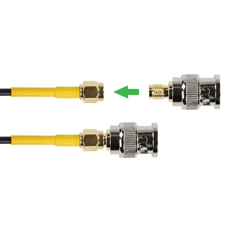
The N to BNC adapter is commonly found in laboratories where newer RF equipment needs to connect with existing test instruments.
The main issue is impedance.
A 50Ω RF system should normally remain 50Ω through the adapter transition.
This maintains the intended RF path.
A mismatch can create measurement problems that are not always visible during normal operation.
Possible symptoms include:
- unstable measurement results
- unexpected return loss
- higher VSWR readings
- inconsistent test repeatability
For laboratory applications, the adapter information should be included in the test record.
A practical test record may include:
| Test Record Item | Example |
| Adapter type | N male to BNC female |
| Impedance | 50Ω |
| Frequency range | DC–6 GHz |
| Application | VNA connection |
| Condition | Calibration completed |
The adapter itself is not usually the biggest loss source in a short RF path, but ignoring it can make measurement results harder to reproduce.
Why Are N to TNC Adapters Used in Rugged RF Systems?
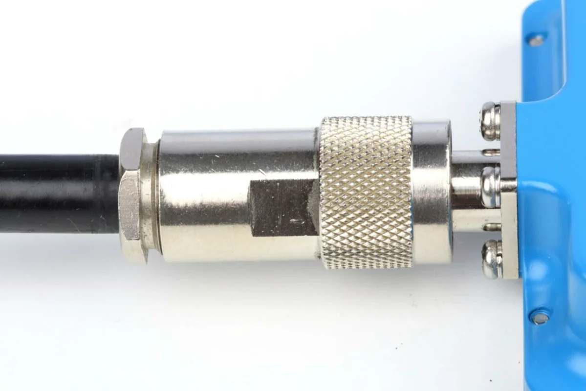
The N to TNCadapter is selected when two threaded RF interfaces need to be connected.
TNC connectors are similar in appearance to BNC connectors, but the coupling mechanism is threaded instead of bayonet style.
That difference matters in environments where vibration, movement, or repeated handling exists.
Typical applications include:
- vehicle communication equipment
- outdoor wireless systems
- antenna installations
- industrial RF devices
A TNC connection is often preferred when the connector needs more mechanical stability than a quick-lock interface.
However, the adapter still needs to match the complete system.
Before selecting an N to TNC adapter, check:
- connector gender
- impedance
- frequency requirement
- installation environment
- sealing requirements
For example, an outdoor antenna system may require attention not only to RF performance but also to mechanical protection. A connection exposed to moisture or vibration may need additional sealing measures.
How Does Impedance Affect N Type Adapter Selection?
An adapter can fit perfectly and still be electrically unsuitable.
Most communication and RF measurement systems using N connectors are based on 50Ω impedance. Maintaining this value through the adapter is necessary to reduce unwanted reflections.
Every transition changes the RF environment slightly.
The effect becomes more noticeable when:
- frequency increases
- cable length increases
- multiple adapters are stacked
- measurement accuracy is important
A common laboratory mistake is adding several adapters to make available equipment connect.
The setup may work physically, but the measurement uncertainty increases.
BNC instrument
This connection may be acceptable for a basic signal check, but it is less suitable for precision RF measurements.
How Can You Check Coax Compatibility Before Selecting an Adapter?
The adapter interface is only one part of the assembly.
The rear connection between the adapter and cable also matters.
A mismatch between adapter and cable can create mechanical and electrical problems.
The front connector may look identical.
The rear structure is different.
This difference affects:
- center contact alignment
- shielding connection
- mechanical strength
- long-term reliability
In production environments, the problem often appears after assembly rather than during initial testing.
Can Similar Looking Coax Connectors Be Used Interchangeably?
No.
Examples:
- A 50Ω N adapter is not automatically suitable for a 75Ω video system.
- A low-frequency coax adapter may not perform correctly at microwave frequencies.
- A connector that mates mechanically may still introduce unacceptable RF mismatch.
A practical selection rule:
Match the RF system first. Match the connector shape second.
For buyers, the safest request includes:
Connector A + Connector B + Gender + Impedance + Frequency + Application
This gives the supplier enough information to avoid selecting a mechanically compatible but electrically unsuitable adapter.
How Do N Type Adapters Compare With Other RF Adapter Families?
An adapter request often starts with a simple sentence:
“We have an N connector here, but our cable uses SMA.”
For purchasing teams, this sounds like a small connection problem.
For RF engineers, there are more details behind it.
The adapter changes the physical interface, but it also becomes part of the transmission path. The wrong adapter may still install correctly while creating problems during measurement or long-term operation.
This is especially common when several connector families appear in the same project:
- N Type for antenna connections
- SMA for RF modules and test cables
- BNC for laboratory instruments
- TNC for mobile or vibration environments
The selection should follow the application first, then the connector family.
Why Are N Type Adapters Commonly Used in Antenna Systems?
N Type connectors are often found at the antenna side of an RF system.
The reason is practical.
Antenna cables are usually installed in places where the connection must handle:
- larger coaxial cables
- repeated maintenance
- outdoor conditions
- mechanical stress
A tower-mounted antenna system, for example, may use an N Type connector because the connection needs to remain stable after installation.
By comparison, SMA connectors are more common inside equipment where space is limited.
The adapter allows different connector systems to work together without changing the original equipment.
However, the adapter should not be selected only because both sides “fit”.
Before ordering, confirm:
| Item | Question to Confirm |
| Interface | Is it N male, N female, SMA male, or SMA female? |
| Impedance | Is the system 50Ω? |
| Frequency | Does the adapter cover the operating band? |
| Installation | Is it for testing or permanent use? |
| Cable | Does the rear connection match the cable type? |
A common mistake is ordering:
N to SMA adapter
without specifying direction.
An N male to SMA female adapter and an N female to SMA male adapter solve different problems.
When Does SMA Become a Better Choice Than N Type?
The smaller size of SMA connectors makes them useful in compact RF systems.
Typical SMA applications include:
- evaluation boards
- RF modules
- microwave test cables
- compact instruments
A laboratory setup may contain several SMA connections because engineers need to change configurations quickly.
In this situation, adding an N Type adapter may only be necessary if the device under test uses an N interface.
The choice is not about connector size.
It is about the role of the connector in the system.
| Application | More Suitable Connector |
| Outdoor antenna feeder | N Type |
| Compact RF module | SMA |
| Test cable connection | SMA or N depending on equipment |
| Industrial RF equipment | N Type or TNC |
A smaller connector can be the correct solution in one project and the wrong solution in another.
How Should You Choose Between N Type, BNC, and TNC Adapters?
These three connector families often appear together in RF laboratories.
The difference is not only electrical. The mechanical connection method also affects where each connector is normally used.
| Connector | Connection Structure | Typical Use |
| N Type | Threaded coupling | Antenna and communication systems |
| BNC | Bayonet locking | Quick laboratory connections |
| TNC | Threaded coupling | Mobile and vibration environments |
BNC is convenient when operators frequently connect and disconnect equipment.
A test engineer may prefer BNC for temporary measurement because the locking method is fast.
TNC is selected when the connection needs more mechanical security.
N Type is commonly used where antenna compatibility and mechanical strength are more important.
The adapter should match the working environment, not just the connector drawing.
How Do N Type Adapters Affect RF Measurement Results?
In RF testing, adapters are often treated as part of the measurement setup.
This matters because the adapter introduces another transition between two interfaces.
A simple example:
A VNA uses SMA ports.
The device under test uses N connectors.
The connection works.
But before measuring, the engineer needs to consider whether the calibration includes the adapter.
Otherwise, the measurement reference plane changes.
Common checks include:
- adapter model
- connector direction
- frequency range
- calibration status
- measurement configuration
A continuity test is not enough.
A connector may show electrical connection while still having problems at higher frequencies.
Possible issues include:
- poor center contact alignment
- damaged plating
- mechanical wear
- incorrect impedance transition
For RF testing, engineers normally verify the adapter using measurements such as:
| Test | Purpose |
| VSWR | Check reflection level |
| Return Loss | Evaluate mismatch |
| Insertion Loss | Check transmission loss |
| Frequency Sweep | Confirm usable range |
When Should You Use an Adapter Instead of a New Cable Assembly?
This is a common discussion during equipment upgrades.
A customer may already have:
- installed antenna cables
- existing RF modules
- older test equipment
Changing every cable is expensive.
An adapter can extend the life of existing equipment.
For temporary work, this is usually practical:
- prototype testing
- laboratory experiments
- troubleshooting
- equipment evaluation
For permanent systems, the decision may change.
A dedicated cable assembly can reduce:
- connection quantity
- installation steps
- mechanical stress
A simple comparison:
| Situation | Suitable Option |
| Engineer testing different modules | Adapter |
| Temporary RF configuration | Adapter |
| Outdoor fixed installation | Cable assembly |
| Production equipment | Cable assembly |
| Frequent interface changes | Adapter |
The important point is knowing when the adapter is solving the actual problem.
If the issue is only connector conversion, an adapter is enough.
If the issue is long-term reliability, cable routing, or environmental protection, a cable assembly may be the better approach.
What Information Should Buyers Provide Before Ordering N Type Adapters?
Many RF sourcing problems start with incomplete product descriptions.
A request like:
Need 500pcs N adapter.
does not define the product.
Before quotation, suppliers usually need:
- connector A
- connector B
- male/female direction
- impedance
- frequency range
- mounting style
- quantity
A clearer requirement:
N female to SMA male adapter, 50Ω, DC–6GHz, straight type, for antenna testing.
For production projects, additional details may be needed:
- cable model
- assembly method
- environmental requirement
- inspection standard
The more complete the specification, the lower the chance of receiving a mechanically correct but unsuitable RF component.
N Type Adapter Selection Checklist
Before placing an order, check these items:
| Check Point | Confirm |
| Connector Side A | N / SMA / BNC / TNC |
| Connector Side B | Required interface |
| Gender | Male or Female |
| Impedance | Usually 50Ω for RF systems |
| Frequency | Above operating frequency |
| Application | Test, antenna, production |
| Quantity | Prototype or mass production |
This simple information is usually enough for suppliers to identify the correct adapter structure.
FAQ
Why does my N Type adapter fit correctly but show poor RF performance?
A mechanical connection does not always mean the RF connection is correct.
Possible causes include incorrect impedance, unsuitable frequency range, poor contact alignment, damaged connector surfaces, or adding too many adapters in the signal path.
For RF applications, the adapter should be selected together with the cable and equipment specifications instead of only matching the connector appearance.
What should be checked before adding an N Type adapter into an RF system?
Before adding an adapter, check the complete RF path instead of only the connector interface.
The main items include:
- connector type and gender
- impedance requirement
- operating frequency
- cable compatibility
- installation environment
- whether the connection is for testing or permanent use
A correct adapter should match the entire system, not just the two connector ends.
I only know the equipment uses an N connector. Is that enough to order an adapter?
Usually not.
“N connector” only identifies the connector family. The adapter still depends on the interface direction, such as N male or N female, and what connector needs to be connected on the other side.
Before ordering, it is better to provide the complete connection:
Equipment port → Adapter → Cable or test port
This avoids situations where the adapter can be installed but cannot be used in the actual RF setup.
Is an N to SMA adapter the same as an SMA to N adapter?
No.
The two descriptions refer to different connection directions.
For example, an N female to SMA male adapter is used in a different situation from an N male to SMA female adapter.
When requesting a quotation, describing both sides separately is clearer:
- N side: male or female
- SMA side: male or female
- application: antenna, test, or equipment connection
What details does a supplier need before recommending an N Type adapter?
A connector picture or a short description is often not enough.
The useful information usually includes:
- connector type on both sides
- male/female requirement
- impedance
- operating frequency
- cable type if applicable
- installation environment
- quantity
For RF applications, these details help avoid selecting a part that looks correct but does not match the actual system.
