
A cable can use the correct connector name and still be wrong for the RF path.
That happens often with N type connector sourcing. The buyer asks for “N male for antenna cable,” the supplier sends a part that mates mechanically, and the first inspection looks fine. The issue shows up later: the cable is too small for the rear body, the assembly is used near a higher frequency than expected, or the system has a power level that the cable—not the connector—cannot safely handle.
N Type is not a small-board connector like SMA, and it is not a quick test connector like BNC. It is often chosen because the RF path needs a stronger threaded interface, a larger coax cable, a field-installed antenna connection, or a higher-power path. That also means the selection cannot stop at “N male” or “N female.” The useful specification includes impedance, cable type, frequency range, power condition, mounting style, and inspection target.
How Does an N Type Connector Fit Into High-Power RF Systems?
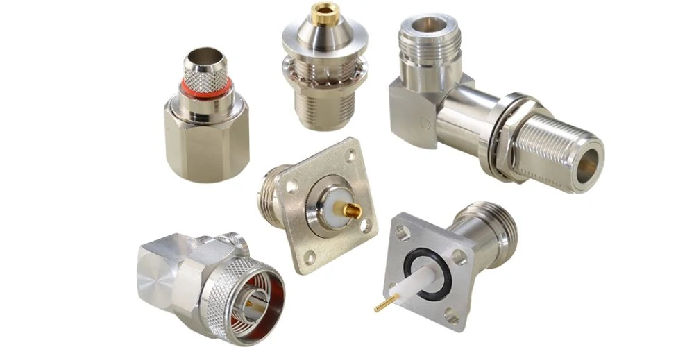
This image presents various N Type RF connector designs and adapter structures. Different mounting styles are available for cable assemblies, panel installation, antenna systems, and RF test equipment. Selecting the correct connector style helps improve installation reliability and RF performance.
N Type connectors are common in RF systems because they solve a practical problem: they provide a threaded coaxial interface that can support larger cable assemblies and more rugged installations than many compact RF connectors.
In antenna systems, test equipment, base station feeds, RF loads, attenuators, splitters, and outdoor cable runs, the connector is not just a metal fitting at the end of the cable. It is part of the controlled RF path. If the connector geometry, impedance, and cable termination are not matched, the assembly may still pass continuity but fail under VNA sweep, power loading, or field vibration.
A typical Type-N connector uses a threaded coupling structure. That threaded connection is useful when the installation cannot tolerate accidental disconnects or loose mating. Compared with BNC, it takes more time to mate, but the locked mechanical engagement is stronger. Compared with SMA, it is larger and less convenient for compact modules, but it can work better with larger coaxial cables and outdoor antenna feeds.
The connector name alone does not define the full performance.
An N type connector used on a short RG58 jumper for lab setup is not the same sourcing problem as an N type connector used on an LMR400 outdoor antenna cable. The front interface may look similar, but the rear body, ferrule, clamp structure, stripping dimension, sealing requirement, and cable strain behavior are different.
Where N Type is usually a better fit
N Type is often used where the RF assembly needs more mechanical strength or where the cable is larger than the small coax used inside compact wireless devices. Common examples include rooftop antenna cables, telecom cabinets, outdoor wireless infrastructure, RF test benches, power attenuator connections, and feeder cables between equipment and antenna hardware.
That does not mean N Type is always better. A small 5G module, GPS board, Wi-Fi device, or compact enclosure may still use SMA, MCX, MMCX, U.FL-style micro coax, or another smaller interface. N Type becomes more attractive when the installation has a larger cable, field handling, repeated connection, or higher mechanical load.
A simple way to think about it:
| RF Situation | Why N Type May Be Used | What Still Needs Checking |
| Outdoor antenna feed | Strong threaded connection, larger cable support | Sealing, cable loss, impedance, installation torque |
| RF test equipment | Stable mating and common lab interface | Frequency range, adapter count, repeatability |
| High-power attenuator/load | Mechanical strength and larger RF path | Power rating, heating, VSWR, duty cycle |
| Telecom cabinet | Rugged connection and serviceability | Cable routing, labeling, panel clearance |
| Long coax run | Works with lower-loss larger cables | Cable type, bend radius, insertion loss |
The mistake is treating the connector as a universal adapter between cable and equipment. In practice, the cable may become the limiting part before the N interface does. A long cable run with high loss will not become low-loss because an N connector is installed at the end. A poorly crimped connector will not become stable because the interface is threaded. The complete assembly matters.
Why N Type is often compared with SMA, BNC, and TNC
Buyers often compare N Type with SMA, BNC, and TNC because these connectors appear in the same RF projects.
SMA is smaller and common on RF modules, instruments, antennas, and compact devices. It can be suitable for high-frequency work, but the cable size and power handling may be limited depending on the assembly. BNC is convenient for quick connection and common in test, video, and lower-frequency bench work, but its bayonet structure is not usually selected when a rugged threaded outdoor feed is needed. TNC uses a threaded coupling and can be useful where vibration resistance is required, but N Type is more common on larger antenna feeder cables and infrastructure equipment.
The comparison is not about which connector is “better.” It is about which connector fits the operating frequency, cable size, power level, equipment port, and installation environment.
How Should You Choose N Male or N Female Connectors?
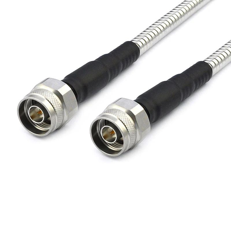
This image shows an N Type male coaxial cable assembly with a threaded RF connector interface. The rugged screw coupling design helps maintain stable mechanical connection and reliable signal transmission in RF systems. It is commonly used with coaxial cables for antenna feeders, communication equipment, and laboratory testing applications.
N male and N female selection sounds simple until the order involves panel mounts, bulkhead fittings, adapters, and cable assemblies.
A standard N male connector usually has a center pin. A standard N female connector usually has a center socket. The coupling structure also differs: the male side typically has the coupling nut, while the female side is commonly the fixed threaded interface on equipment, panel hardware, or an adapter body.
For sourcing, do not rely only on the words “male” and “female” from a customer message. Check the actual equipment port. Product photos, outline drawings, or sample hardware are safer than a short text description.
A common ordering mistake is this: the customer says “N female cable,” but they mean the cable should connect to an N female port on the equipment. In that case, the cable side may need an N male connector. This confusion is especially common when the buyer describes the mating port instead of the connector being ordered.
Cable-end, panel-mount, and bulkhead N connectors are not the same order
An N type cable plug is selected around the coax cable. The important details include cable OD, dielectric size, braid structure, ferrule or clamp method, center pin termination, and stripping dimension.
A panel-mount or bulkhead N type connector has a different selection logic. The buyer must confirm panel thickness, thread length, flange or nut style, sealing gasket, grounding path, and whether the connector is used as a feedthrough or part of a cable assembly.
For example, “N female bulkhead” may refer to several different structures:
| Request Phrase | Possible Meaning | Detail to Confirm |
| N female bulkhead connector | Female front interface through a panel | Panel thickness, nut style, gasket |
| N female 4-hole flange | Fixed flange mounted to equipment | Hole spacing, screw size, body length |
| N female to N female adapter | Feedthrough adapter | Both sides gender, impedance, frequency |
| N female for cable | Cable-end female connector | Cable type, termination style, strain relief |
| N female waterproof connector | Outdoor or sealed version | IP requirement, O-ring, installation condition |
This is why a complete RF requirement should never be only “N female connector.” It should include the mating side, cable or panel requirement, impedance, frequency range, and application.
A better requirement looks like this:
50 ohm N male connector for LMR400 cable, outdoor antenna feeder application, DC–6 GHz, crimp/clamp termination, low VSWR required at operating band.
That sentence gives the supplier something useful to check. It reduces the chance that the part will mate but fail during assembly or testing.
Avoid bulk ordering from photos only
Photos help, but they do not confirm RF performance.
Two N type connectors may look almost identical from the front and still be different in cable fit, insulator material, plating, frequency rating, waterproof structure, or termination method. For small sample orders, a photo may be enough to start discussion. For production, the supplier should confirm drawings, cable compatibility, and inspection requirements.
This matters more when the assembly will be used with higher power, long cable runs, or outdoor installation. A wrong rear body may loosen after bending. A wrong ferrule may not grip the braid correctly. A poorly matched cable connector may pass the first pull check but show unstable VSWR after movement.
The safe approach is simple: identify the connector gender by the interface, then specify the cable or mounting structure behind it.
How Do 50 Ohm Systems Affect N Type Connector Selection?
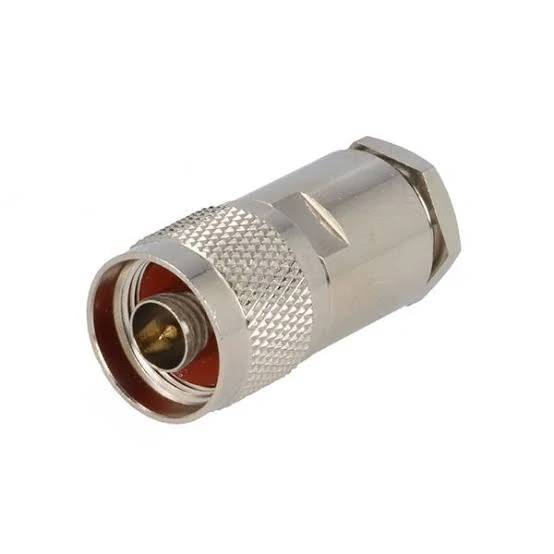
This image shows an N Type male cable connector designed for coaxial cable termination. When selecting an N Type connector, engineers should consider cable compatibility, impedance matching, operating frequency, and mechanical installation requirements to ensure stable RF performance.
A connector that fits mechanically can still be wrong electrically.
Most RF communication and test systems using N type connector assemblies are built around a 50 ohm signal path. That means the connector, cable, adapter, load, antenna, splitter, attenuator, and instrument port should all be selected around the same impedance target. If one part of the chain is different, the result may not be obvious during visual inspection. The problem appears as higher VSWR, unstable return loss, unexpected insertion loss, or inconsistent measurement results.
N Type connectors are available in different impedance versions. That is why “N connector” is not enough for a production order. A 50 ohm N type connector and a 75 ohm version may look close enough to confuse a buyer, especially in online listings or mixed warehouse bins. The safer BOM wording should state the impedance directly.
A better line item is:
N type male connector, 50 ohm, for RG213 cable, DC–6 GHz, silver-plated body, gold-plated contact, PTFE insulator, crimp/clamp termination.
That gives the supplier more than a front-interface name. It tells them which RF system the connector must support.
Match the connector impedance with cable and equipment
The most common sourcing mistake is confirming only the equipment port.
For example, a buyer may say the device has an N female port, so thy need an N male cable. That is only the first step. The next question is whether the equipment port is 50 ohm or 75 ohm, what cable is being used, and what frequency band the assembly must support.
A 50 ohm RF system should not be mixed with a 75 ohm connector just because the parts can be forced into a similar mechanical arrangement. Mechanical mating is not the same as RF compatibility. At low frequency or during a quick bench test, the difference may be hidden. At higher frequency, longer cable length, or tighter VSWR limits, the mismatch becomes more visible.
A practical 50 ohm check should include:
| Check Item | What to Confirm | Why It Matters |
| Equipment port | N male, N female, or another interface | Prevents ordering the wrong mating gender |
| System impedance | 50 ohm or 75 ohm | Avoids mismatch in the RF path |
| Cable type | RG58, RG213, RG214, LMR240, LMR400 | Controls rear body and termination choice |
| Adapter count | None, one, or multiple adapters | Each adapter can add mismatch and loss |
| Operating band | MHz or GHz range | Determines whether rating margin is enough |
| Test target | VSWR, return loss, insertion loss | Defines acceptance before shipment |
This checklist is useful because it forces the order to move from a connector name to a system requirement.
How Does Frequency Range Change N Type Connector Choice?
Not every N type connector should be treated as the same frequency part.
Frequency rating depends on connector geometry, dielectric material, internal transition design, machining precision, termination quality, and how well the connector fits the cable. A general-purpose N connector used for low-frequency antenna work may not be the right part for a higher-frequency test assembly. The front interface may still be N Type, but the RF behavior can change.
The usual rule is simple: the whole assembly is limited by the weakest part.
If the connector is rated higher than the cable, the cable becomes the bottleneck. If the cable is suitable but the adapter is not, the adapter becomes the bottleneck. If the connector body is good but the assembly is poorly terminated, the termination becomes the bottleneck.
Check rated frequency before assuming all N connectors are equal
For procurement, it is safer to specify the required operating band rather than asking only for a connector type.
For example:
50 ohm N female bulkhead connector, DC–6 GHz, panel-mount, low VSWR required from 700 MHz to 2.7 GHz.
This tells the supplier the full rating and the real band of concern. It also gives the inspection team a target. A part may be sold as DC–6 GHz, but the customer may only care about 2.4 GHz. Another customer may use the same connector style near the upper rating and need tighter return loss control.
Frequency margin matters more when the assembly is used in measurement, not just connection. A cable used between an antenna and radio may tolerate a different loss target than a VNA test cable, calibration accessory, or production test fixture.
A useful internal rule is:
Frequency Margin Ratio = Connector Rated Frequency ÷ Highest Operating Frequency
| Frequency Margin Ratio | Practical Meaning | Suggested Action |
| Below 1.0x | Rating is not enough | Do not use |
| 1.0x–1.2x | Minimal margin | Use only if test result is acceptable |
| 1.2x–1.5x | General working margin | Suitable for many ordinary RF links |
| 1.5x–2.0x | Better margin | Preferred for test leads or low-VSWR work |
| Above 2.0x | Stronger margin | Useful where repeatability matters |
This is not a universal standard. It is a sourcing judgment tool. Exact acceptance still depends on the measured VSWR, insertion loss, cable length, adapter count, and customer requirement.
How Much RF Power Can an N Type Connector Handle?
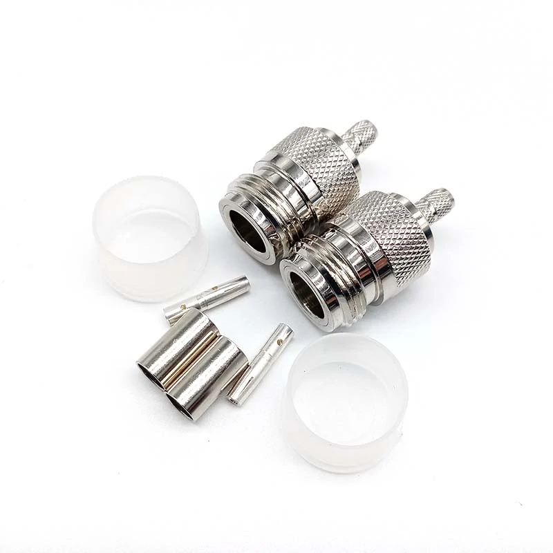
This image displays the internal components of an N Type cable connector assembly, including connector bodies and termination parts. The assembly process requires precise matching of cable size, stripping dimensions, and termination methods to maintain signal integrity and connection reliability.
Power handling is often misunderstood because buyers want one number.
The honest answer is that an N type connector can be used in higher-power RF systems, but the safe operating power is not decided by the connector name alone. It depends on frequency, cable size, VSWR, insertion loss, ambient temperature, duty cycle, ventilation, mating condition, and whether the connection is stable under load.
A connector on a short low-loss cable may behave differently from the same connector installed on a long lossy cable inside a warm cabinet. Poor mating or high VSWR can cause reflected power and heating at the connection point. A loose or contaminated interface makes the risk worse.
Separate connector power from cable power and system power
For buying and engineering review, split the question into three parts:
| Power Question | Meaning | Common Risk |
| Connector rating | What the connector design can support under stated conditions | Rating is assumed without checking frequency and heat |
| Cable power limit | What the coax cable can safely handle | Thin cable overheats before connector limit |
| System power condition | Real RF power after mismatch, duty cycle, and environment | Bench test passes, field installation runs hot |
This distinction prevents overconfidence. A larger N type interface does not make a small cable suitable for high power. RG316, RG58, RG213, LMR240, and LMR400 do not have the same loss or power behavior. The cable selection must match the actual RF level.
If the customer provides power in dBm, convert it before choosing a connector or cable assembly:
P(W) = 10^((dBm – 30) / 10)
Then compare the operating power with the rated power of the connector and cable assembly.
Power Utilization = Operating Power ÷ Rated Power × 100%
For production sourcing, it is better to avoid running too close to the rating. A part used at the edge of its rating may pass a short test and still become risky under higher temperature, long duty cycle, poor airflow, or repeated mating.
N Type Power Margin Estimator
Use this as a practical review table before confirming a higher-power N type connector assembly.
| Input | Record |
| Input Power | dBm or W |
| Operating Frequency | MHz or GHz |
| Cable Type | RG58 / RG213 / RG214 / LMR240 / LMR400 / other |
| Cable Length | mm or m |
| Cable Loss | dB at operating frequency |
| VSWR Target | Customer requirement |
| Duty Cycle | Continuous / intermittent / pulse |
| Connector Rating | W under stated condition |
| Installation Environment | Open bench / cabinet / outdoor / high temperature |
| Safety Margin | Accept / Review / Choose higher-power assembly |
Output decision:
- If utilization is low and the cable is suitable, the assembly may be acceptable.
- If utilization is close to the rating, review heating, duty cycle, and VSWR.
- If the cable is small or loss is high, select a larger cable or higher-power assembly instead of only changing the connector.
Which Coax Cable Works Best With N Type Connectors?
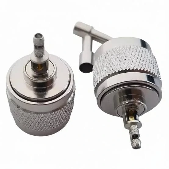
This image shows different N Type connector structures, including male and female RF interfaces. N Type connectors are commonly used in antenna systems, RF equipment, adapters, and cable assemblies where a reliable threaded connection is required.
The cable should be selected before the rear connector structure is finalized.
N type coax connectors are used with many cable families, including RG58, RG213, RG214, RG316, LMR240, and LMR400. The front interface may stay the same, but the cable-entry design changes. A connector made for RG58 should not be treated as interchangeable with one made for LMR400. The cable OD, dielectric diameter, braid structure, and termination method are different.
Match N type coax connectors with cable diameter and structure
Short lab jumpers may use flexible cables such as RG58 or RG316, depending on the frequency and loss target. Longer outdoor feeder lines often use larger, lower-loss cables such as LMR240 or LMR400. For higher shielding or lower loss requirements, the cable structure may change agai.
A rough sourcing view:
| Cable Type | Typical Use With N Type | Selection Caution |
| RG58 | Short RF jumper, general antenna cable | Higher loss than larger low-loss cables |
| RG213 | Larger RF feeder, rugged cable assembly | Requires correct rear body and clamp/crimp method |
| RG214 | Shielded RF cable assembly | Confirm diameter and termination style |
| RG316 | Short flexible jumper, compact routing | Not ideal for high power or long runs |
| LMR240 | Lower-loss medium-size antenna cable | Confirm compatible connector body |
| LMR400 | Long outdoor feeder, lower-loss link | Larger bend radius and connector size |
Cable choice affects more than loss. It affects bend radius, installation stress, pull force, termination repeatability, and packaging. A cable that looks good in a product photo may be too stiff for the customer’s enclosure. A very flexible cable may route well but lose too much signal at higher frequency.
For buyers, the safest request is not “N type cable.” It is:
50 ohm N male to N male cable assembly, LMR400 equivalent cable, 2 meters, outdoor antenna use, operating band 700–2700 MHz, VSWR test required before shipment.
That request gives the supplier enough information to choose the correct connector body, cable, termination process, and inspection method.
A finished N type connector assembly is only as good as the match between the front interface, the rear cable structure, and the RF target. That is where many sourcing problems begin—and where a careful specification saves the most time.
When Should You Use an N Type Adapter?
An adapter should be treated as an RF component, not a small piece of hardware added at the end of the order.
N type adapters are useful when the system needs a controlled transition between two interfaces. Common examples include N to SMA, N to BNC, N male to N female, N bulkhead feedthrough, and adapter combinations used on test equipment or antenna hardware. The adapter may solve a mechanical connection problem, but it also adds another mating point to the RF path.
That extra interface can add insertion loss, return loss variation, mechanical length, and another point where torque or alignment may be wrong. For low-frequency, low-power, or short cable setups, the effect may be minor. For higher-frequency measurement, long cable chains, low-VSWR requirements, or power systems, the adapter needs to be selected more carefully.
Use N type adapters for controlled interface transitions
A clean adapter transition has three requirements.
First, the impedance should match the system. If the RF path is 50 ohm, the adapter should also be 50 ohm. Second, the frequency rating should cover the operating band with enough margin. Third, the mechanical interface should match the real mating hardware, not only the product title.
A common case is outdoor antenna hardware with an N female port and a compact RF module with an SMA female port. The buyer may need an N male to SMA male adapter, or a short N-to-SMA cable assembly, depending on space and strain. A direct adapter may look convenient, but it can put mechanical load on the smaller SMA port. A short adapter cable may be safer if the radio module is mounted inside an enclosure or exposed to vibration.
For test benches, adapters are also common because instruments, attenuators, loads, and DUT fixtures may not share the same interface. But adapter stacks should be kept under control. A chain such as N to SMA, SMA to BNC, then BNC to another fixture may be easy to build in the lab, but it becomes difficult to repeat in production testing.
Choose N type to SMA adapters when connecting antennas to compact RF devices
N type to SMA adapters are often used where a larger antenna feed needs to connect with compact RF equipment. This is common in wireless infrastructure, antenna testing, IoT gateways, RF modules, and lab setups.
The important question is not only “Does N connect to SMA?” It is whether the transition is acceptable for the frequency, power, and mechanical load.
| Adapter Use Case | Common Reason | Main Risk | Better Check |
| N antenna to SMA radio | Interface mismatch between antenna feed and device | Stress on SMA port | Use short cable assembly if strain is high |
| N test cable to SMA DUT | Lab measurement convenience | Extra mismatch near upper band | Sweep with adapter included |
| N attenuator to SMA module | Power path transition | SMA side may limit power | Confirm lowest-rated component |
| N bulkhead to SMA inside box | Panel feedthrough to compact board | Tight bend or connector leverage | Check enclosure clearance |
A direct adapter is acceptable when the mechanical load is low and the RF requirement is not tight. For field hardware, a flexible jumper may be a safer decision.
Use N type to BNC adapters only when the application allows the transition
N type to BNC adapters are usually selected for test convenience or mixed equipment. BNC is quick to connect and common on many instruments. N Type is more common on antenna feeds, RF loads, attenuators, and larger coaxial cable assemblies.
This transition should not be automatic. BNC versions vary by impedance and frequency use. If the system is 50 ohm, the BNC side must also be selected as 50 ohm. If the application is near a higher frequency or has a strict VSWR requirement, the adapter should be included in the actual test setup rather than assumed acceptable.
For production, write the adapter requirement clearly:
50 ohm N male to BNC female adapter, DC–1 GHz operating use, for RF test bench connection, VSWR inspection required.
That is much better than “N to BNC adapter.”
How Do N Type Connectors Compare With SMA, BNC, and TNC?
A connector comparison is useful only when it includes the job each interface is expected to do.
N Type, SMA, BNC, and TNC often appear in the same RF sourcing conversation because customers may use them in one signal chain. An outdoor antenna may use N Type. A compact radio module may use SMA. A bench instrument may use BNC. A vibration-sensitive device may use TNC. The system then needs cables and adapters that connect those interfaces without creating an uncontrolled RF path.
The comparison below is practical, not absolute.
| Connector Interface | Common Strength | Common Limitation | Typical Buying Question |
| N Type | Rugged threaded interface, larger cable support | Larger size, not ideal for compact modules | Is this for antenna feed, power path, or test equipment? |
| SMA | Compact size, common in RF modules and high-frequency hardware | Smaller interface, cable and power limits vary | Is the SMA side the limiting component? |
| BNC | Fast bayonet connection, easy for bench work | Less rugged than threaded interfaces | Is quick mating more important than locked connection? |
| TNC | Threaded interface with better vibration resistance than BNC | Less common than N Type in larger feeder systems | Is vibration the main concern? |
No connector should be substituted only because it is available in stock. A change from N Type to SMA may reduce size but affect power handling and cable choice. A change from N Type to BNC may improve convenience but reduce mechanical security. A change from BNC to TNC may improve locking, but it still requires checking impedance, frequency, and cable compatibility.
Compare N Type and SMA when frequency and size matter
SMA is often selected for compact RF devices, test boards, modules, small antennas, and high-frequency assemblies. N Type is usually selected when the cable is larger, the port is on outdoor or infrastructure equipment, or the connection needs stronger field handling.
If the system uses an N type antenna and an SMA radio module, do not force a rigid adapter unless the mechanical load is safe. A short N-to-SMA cable assembly may reduce stress and make routing easier. The extra cable length adds loss, but a damaged SMA port is a worse problem.
Compare N Type and BNC when quick connection is less important than ruggedness
BNC is convenient. That is why it appears on many test benches. The bayonet structure is fast, easy to handle, and useful when cables are connected and disconnected often.
N Type is slower to mate but more secure. For outdoor feeders, cabinet connections, antenna systems, and higher-mechanical-load assemblies, the threaded coupling is usually the safer structure. If a buyer asks to replace an N interface with BNC only to make connection faster, the application should be reviewed first.
Compare N Type and TNC when vibration and installation style matter
TNC is also a threaded RF connector, so it may be useful where vibration is a concern and BNC is not secure enough. N Type, however, is more common for larger coax runs, outdoor antenna feeds, and infrastructure equipment.
The practical question is usually cable and installation style. If the assembly uses a larger feeder cable, N Type may fit better. If the device needs a smaller threaded interface with vibration resistance, TNC may be the better fit.
How Can You Test N Type Connector Assemblies Before Use?
Do not rely on DC continuity alone.
A cable assembly can pass continuity and still show poor RF behavior. The center conductor may connect, the shield may connect, and the connector may look clean, but the assembly can still have poor return loss, unstable VSWR, or excessive insertion loss at the operating frequency.
For N type connector assemblies, the test level should match the application. A simple low-frequency antenna jumper may need basic inspection and continuity. A production RF test cable or high-power feeder should be checked more carefully.
Inspect mechanical condition before RF testing
Start with the visible and mechanical details:
- thread damage
- center contact position
- plating condition
- dielectric damage
- gasket or O-ring condition
- cable jacket damage
- ferrule or clamp tightness
- connector body rotation
- label and cable length
Mechanical inspection will not prove RF performance, but it catches avoidable failures before VNA testing. A damaged thread can cause poor mating. A recessed or bent center contact can create unstable connection. A loose rear body can change performance when the cable is moved.
Measure S11, VSWR, and insertion loss across the required band
For RF validation, test across the actual operating band. Do not test only at one convenient frequency unless the customer requirement is truly narrow.
Useful measurements include:
| Test Item | What It Shows | When It Matters |
| S11 / Return Loss | Reflection caused by mismatch | Antenna feeds, test cables, low-VSWR systems |
| VSWR | Practical mismatch indicator | Quotation acceptance and production inspection |
| Insertion Loss | Signal loss through cable and connectors | Long cable runs, higher-frequency systems |
| Continuity | Basic electrical connection | Incoming inspection, low-risk assemblies |
| Insulation Resistance | Isolation between center and shield | Safety and quality checks |
| Re-mate Repeatability | Change after repeated connection | Test labs and production fixtures |
The adapter used during test should be recorded. If the test setup includes an N-to-SMA adapter, that adapter becomes part of the measurement. A poor adapter may make a good cable look bad. A good adapter may also hide a problem that appears when the customer uses a different adapter.
Repeat mating tests when connector repeatability matters
Repeatability matters in test labs, calibration setups, and production fixtures. A connector that performs well once may shift after multiple mating cycles if the center contact is weak, the plating is damaged, or the mating torque is inconsistent.
For repeatability checks, record:
- torque consistency
- number of mating cycles
- contact wear
- cable movement sensitivity
- adapter influence
- change in VSWR or return loss
This does not need to be done for every low-cost cable assembly. It is useful where a failure would stop production testing or cause measurement disputes.
N Type Assembly RF Acceptance Matrix
Use this matrix when the assembly needs documented acceptance before shipment.
| Parameter | Record |
| Connector Gender | N male / N female / mixed |
| Connector Style | Cable mount / bulkhead / panel mount / adapter |
| Cable Type | RG58 / RG213 / RG214 / RG316 / LMR240 / LMR400 |
| Assembly Length | mm / m |
| System Impedance | 50 ohm / 75 ohm |
| Frequency Range Tested | MHz / GHz |
| S11 / Return Loss | dB |
| VSWR | Value |
| Insertion Loss | dB |
| Torque Applied | N·m |
| Adapter Used in Test | Yes / No, model if known |
| Re-mate Repeatability | Pass / Fail |
| Final Result | Accept / Reject / Review |
This table helps both engineering and purchasing teams. Engineering gets test traceability. Purchasing gets a clearer acceptance basis. The supplier gets fewer vague disputes after delivery.
How Do You Specify an N Type Connector for Quotation?
A good quotation request reduces back-and-forth before the order is placed.
A vague request like “N connector for antenna cable” forces the supplier to guess. The guess may be correct for the first sample and wrong for production. A complete request should include the RF requirement, mechanical structure, cable information, and inspection target.
Before sending an inquiry, confirm:
- gender
- impedance
- cable type
- connector style
- mounting style
- frequency range
- power condition
- plating requirement
- sealing requirement
- quantity
- test requirement
- labeling or packaging requirement
A complete quotation statement may look like this:
50 ohm N type male connector for LMR400 cable, outdoor antenna application, DC–6 GHz, crimp/clamp termination, low VSWR requirement, 500 pcs, packed with part number label.
For a panel or bulkhead part:
50 ohm N female bulkhead connector, panel-mount, DC–6 GHz, gasket required, panel thickness 2.0 mm, gold-plated center contact, VSWR test at 2.4 GHz.
For an adapter:
50 ohm N male to SMA female adapter, DC–6 GHz, used between outdoor antenna cable and compact RF module, sample test required before bulk order.
The best quotation requests are not long. They are specific.
Why Are Outdoor and Infrastructure RF Systems Still Using N Type Connectors?
N Type remains common because many RF systems still need a strong, serviceable, threaded interface for larger coaxial cables.
Outdoor antennas, rooftop equipment, telecom cabinets, wireless infrastructure, RF loads, and test systems often need more than a compact connector. They need a connection that can be installed in the field, tightened properly, inspected visually, and replaced when needed. N Type fits that role well.
That does not make it the default answer for every RF design. A compact module may use SMA. A small internal cable may use MCX, MMCX, or a micro coax connector. A quick bench connection may use BNC. The reason N Type stays in use is that many RF systems still have large cables, outdoor runs, power handling needs, and service requirements.
For procurement teams, the final rule is simple:
Do not buy only the connector name. Buy the complete RF fit.
That means interface, gender, impedance, cable compatibility, frequency margin, power condition, installation environment, and test acceptance all need to be visible in the order.
If the cable assembly will be used near the upper frequency range, in an outdoor antenna path, or under higher RF power, send the operating frequency, cable type, length, connector count, adapter count, power level, and inspection target before ordering. That information helps confirm whether a standard N type connector is enough or whether the cable assembly needs a higher-margin design.
FAQ
Is an N type connector always 50 ohm?
No. N type connectors can exist in different impedance versions, so the system requirement should be confirmed before ordering. Many RF communication and test systems use 50 ohm parts, but the buyer should still specify 50 ohm in the BOM. Do not rely only on appearance, because a connector may mate mechanically while still being wrong for the RF path.
How do I tell if an N connector is male or female?
Check the center contact and the mating structure. A standard N male connector usually has a center pin, while a standard N female connector usually has a center socket. For purchasing, also check whether the customer is describing the connector they need or the equipment port it must connect to. That is a common source of wrong orders.
Can I use an N type connector with SMA equipment?
Yes, but the transition should be controlled. You can use an N type to SMA adapter or an N-to-SMA cable assembly. Confirm impedance, frequency range, power limit, and mechanical stress. If the N side uses a large outdoor cable and the SMA side is on a compact device, a short jumper may protect the SMA port better than a rigid adapter.
Can an N type connector handle high power?
It can be used in higher-power RF systems, but the safe power level depends on the complete assembly. Check connector rating, cable type, frequency, VSWR, duty cycle, temperature, and ventilation. A larger N interface does not make a small coax cable suitable for high power. The cable or adapter may become the limiting part.
When should I choose a bulkhead N type connector?
Choose a bulkhead N type connector when the RF signal needs to pass through a panel, enclosure, antenna housing, cabinet, or test fixture. Confirm panel thickness, nut or flange style, gasket, grounding path, impedance, frequency range, and mating side. Bulkhead selection is mechanical and RF-related at the same time, so do not order only by gender.
