
A directional coupler can pass every basic inspection and still create problems duringRF testing.
A common situation happens during system debugging: the cable connection is correct, the signal is present, and the power level looks normal. However, once a spectrum analyzer or power meter is connected for monitoring, the measured value does not match the expected result.
The reason is often not the instrument.
It can be the RF sampling method.
Adding a measurement point into an active RF path is not as simple as inserting a connector or using a standard splitter. At higher frequencies, the additional component changes the impedance environment, introduces loss, and may affect the signal being measured.
This is where a directional coupler is normally considered.
Instead of dividing the entire RF signal into separate paths, a directional coupler takes a controlled sample from the main transmission line.
This design is widely used in:
- transmitter power monitoring
- RF calibration systems
- antenna testing
- microwave measurement setups
- production test equipment
For engineers and buyers, selecting a directional coupler is less about finding a component with the right connector. The actual decision depends on coupling value, frequency range, isolation, directivity, and how the sampled signal will be used.
How Does a Directional Coupler Control RF Signal Sampling?
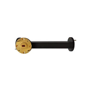
A directional coupler is a passive RF component that provides a sampling path from the main transmission line. It is widely used in transmitter monitoring, antenna testing, RF calibration, and communication equipment.
When engineers need to observe an RF signal, there are several possible approaches.
One option is using a power splitter. Another is adding attenuation before measurement equipment. A third option is using a directional coupler.
These components may appear similar from a catalog view, but they solve different problems.
A splitter is designed to distribute RF power.
A directional coupler is designed to monitor RF power.
That difference affects how the component behaves inside the system.
For example, a transmitter may deliver several watts of RF power toward an antenna. A test engineer may need only a small sample signal to check output power or frequency stability.
Connecting the measurement equipment directly to the main line may overload the instrument or disturb the system.
A directional coupler provides another route:
Main RF path:
Input → Output
Measurement path:
Input → Coupled Port
The measurement device receives only the required signal level while the main RF transmission continues normally.
Understand Why Engineers Sample RF Signals Instead of Splitting All Power
A frequent purchasing mistake is selecting a splitter because the product description appears similar.
The difference becomes clear when looking at the intended function.
| Component | Main Purpose | Typical Use |
| Directional Coupler | Extract a controlled RF sample | Power monitoring and measurement |
| Power Splitter | Divide one signal into multiple outputs | Antenna distribution |
| Attenuator | Reduce signal amplitude | Protect sensitive equipment |
| Dummy Load | Absorb RF energy | RF termination testing |
A splitter normally tries to maintain balanced output paths.
A directional coupler tries to maintain the original signal path while providing measurement access.
For a laboratory test setup, this distinction may only affect measurement convenience.
For a production transmitter, the difference can affect system stability.
Identify the Four Ports Before Connecting a Directional Coupler
Most RF directional couplers have four ports:
- Input Port
- Output Port
- Coupled Port
- Isolated Port
The first two ports belong to the main RF route.
The coupled port provides the sampled signal.
The isolated port improves the directional characteristics of the component by reducing unwanted reverse signal coupling.
This port arrangement is one reason directional couplers cannot always be installed like a simple adapter.
A common field issue is connecting the coupler in the wrong direction.
The RF signal may still pass through the component, which makes the problem difficult to notice during a basic check. However, the coupled output may no longer represent the expected forward power.
Before installation, engineers usually confirm:
- signal direction
- port marking
- unused port termination
- required measurement point
A continuity test only confirms that the circuit is connected. It does not confirm RF behavior.
How Do You Calculate the Coupling Factor of a Directional Coupler?
The coupling factor is usually the first number engineers check when reviewing a directional coupler specification.
This calculation is simple, but it prevents a common selection error.
A coupler that provides too much sampled power may overload the measurement device.
A coupler with excessive coupling loss may produce a signal that is too weak to measure accurately.
Calculate Output Power After Coupling Loss
The basic estimation is:
Pcoupled = Pinput – C
However, practical RF systems include additional factors.
The final measurement value can be affected by:
- insertion loss
- operating frequency
- connector transition loss
- cable attenuation
- measurement tolerance
The main transmission path also needs attention.
A directional coupler is inserted into the RF line, so engineers normally check:
Pmain = Pinput – IL
where IL represents the insertion loss.
For high-power systems, even a small increase in insertion loss can create additional heat and reduce system efficiency.
Avoid Choosing Coupling Value Without Considering Measurement Purpose
There is no universal “best” coupling factor.
The correct value depends on the application.
| Coupling Factor | Suitable Situation |
| 10 dB | Stronger sample signal required |
| 20 dB | General RF monitoring |
| 30 dB | Lower-level measurement protection |
A 20 dB coupler is often selected for general monitoring because it provides a practical balance.
However, a laboratory receiver with a sensitive input may require a different value.
The specification should start from the measurement equipment requirement, not only from available inventory.
Directional Coupler Sampling Calculator
Before selecting a directional coupler, engineers can estimate whether the coupled output matches the measurement device.
| Input Item | Required Data |
| RF Input Power | dBm / W |
| Coupling Factor | dB |
| Operating Frequency | GHz |
| Main Path Loss | dB |
| Measurement Port | Coupled / Main Output |
Calculation:
Coupled Port Power
Pᶜ = Pᶦⁿ – C
Main Output Power
Pᵐ = Pᶦⁿ – IL
Recommended verification:
- Is the coupled signal inside the detector range?
- Is the main path loss acceptable?
- Does the frequency stay within specification?
- Is enough margin available for system variation?
This simple calculation helps avoid ordering a coupler that is electrically correct on paper but unsuitable for the actual test environment.
Which Directional Coupler Specifications Matter Before Selection?
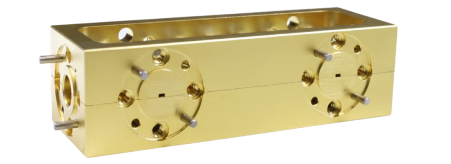
Example of a microwave RF module application where directional couplers and related passive components help engineers monitor and control RF signals.
A specification sheet can look complete and still leave important questions unanswered.
For example, two RF couplers may both be marked as:
- SMA interface
- 50 ohm impedance
- DC–6 GHz frequency range
At first glance, they appear interchangeable.
However, the actual RF behavior depends on several less obvious parameters:
- coupling tolerance
- insertion loss
- isolation
- directivity
- VSWR
- power handling
This is where many purchasing mistakes happen.
The connector style is only the mechanical interface. It does not tell you how accurately the component samples the RF signal.
A directional coupler used in a laboratory measurement system and one used inside a transmitter may have completely different priorities.
The laboratory version may focus on measurement accuracy.
The transmitter version may focus on power handling and long-term stability.
Check Coupling Factor Based on the Required Measurement Range
The coupling factor determines how much RF power appears at the coupled port.
A lower coupling value means a stronger sample signal.
A higher coupling value means a weaker sample signal.
Neither option is automatically better.
The correct choice depends on what happens after the coupled port.
For example:
A power amplifier output may run at 40 dBm.
A 10 dB directional coupler would provide approximately 30 dBm at the coupled port.
That may be useful for some measurement systems but too high for a sensitive analyzer input.
Using a 30 dB coupler would reduce the sampled signal to approximately 10 dBm, creating a safer measurement condition.
| Coupling Value | Sample Output Level | Common Application |
| 10 dB | Higher coupled power | Higher-level monitoring |
| 20 dB | Medium sample power | General RF testing |
| 30 dB | Lower sample power | Sensitive measurement systems |
The correct selection method is:
RF power level → measurement device range → coupling value
Not:
Available model → system adjustment
That difference matters during both prototype testing and mass production.
Compare Isolation and Directivity When Evaluating Signal Separation
Many buyers focus on coupling value and ignore isolation.
This can become a problem when the system needs to measure forward and reflected power.
Isolation describes how well unwanted signals are prevented from reaching the wrong port.
Directivity describes how effectively the directional coupler separates forward power from reverse power.
A coupler with poor directivity may show inaccurate readings because reflected energy enters the measurement path.
This becomes noticeable in applications such as:
- antenna tuning
- VSWR testing
- RF power amplifier evaluation
- transmitter calibration
A measurement error does not always mean the instrument is wrong.
Sometimes the RF component itself is not separating the signals properly.
For engineers evaluating a directional coupler, isolation and directivity should be reviewed together.
Balance Insertion Loss Against Measurement Accuracy
A directional coupler is installed directly into the RF transmission path.
That means the main signal always sees the component.
Even though the purpose is sampling, the primary line still has to maintain acceptable performance.
Important parameters include:
- insertion loss
- return loss
- VSWR
- frequency response
A common misunderstanding is that a directional coupler only affects the coupled port.
In reality, the main output path also experiences loss.
For a low-power laboratory setup, a small loss difference may not matter.
For a high-power RF system running continuously, it can affect:
- thermal load
- efficiency
- output power margin
The complete RF path should be considered:
RF source → cable → connector → directional coupler → load
A coupler cannot compensate for poor cable selection, excessive adapters, or incorrect impedance matching.
How Does Frequency Range Affect Directional Coupler Selection?
A directional coupler rated for a certain frequency range is not only defined by its connector.
The internal RF structure determines whether the component can maintain stable performance across the band.
At low frequencies, small mechanical differences may have limited impact.
At microwave frequencies, those same differences become electrical problems.
Match the Coupler Bandwidth With the Operating RF System
Frequency range is usually the first specification checked, but it should not be the only one.
A coupler operating near the top of its frequency range may experience changes in:
- coupling flatness
- insertion loss
- isolation
- return loss
For example:
A DC–3 GHz coupler and a DC–18 GHz coupler may both use SMA connectors.
The outside appearance can be almost identical.
However, they are not necessarily suitable replacements.
The higher-frequency version requires tighter control of:
- conductor geometry
- dielectric structure
- connector transition
- machining tolerance
For RF engineers, frequency margin is often worth considering.
Operating exactly at the component limit leaves less room for production variation.
Understand Why Microwave Couplers Require Tighter Mechanical Control
A microwave coupler is a precision RF structure.
The physical distance between conductors, the dielectric material, and the internal transmission line dimensions all affect the final response.
Small changes can influence:
- coupling value
- directivity
- isolation
- VSWR
This is why microwave coupler manufacturing requires more than simple mechanical assembly.
Production control may include:
- dimensional inspection
- connector alignment checking
- VNA testing
- frequency sweep verification
A component can look perfect under visual inspection and still fail RF testing.
That is a common difference between ordinary electrical inspection and microwave inspection.
Avoid Using a Low-Frequency Coupler in Microwave Systems
One of the easiest mistakes during sourcing is replacing a higher-frequency component with a similar-looking lower-frequency model.
The reason is simple:
The connector fits.
The mechanical drawing looks similar.
The price may also be lower.
But the RF performance may not meet the application.
Before substitution, verify:
| Check Item | Why It Matters |
| Frequency Range | Confirms operating bandwidth |
| Coupling Accuracy | Ensures measurement consistency |
| Isolation | Prevents unwanted signal leakage |
| Directivity | Separates forward and reverse signals |
| Power Rating | Prevents component damage |
A directional coupler should be selected according to the RF requirement, not only the physical connection.
How Do Connector Interfaces Change RF Coupler Integration?
The connector is often the first thing buyers notice.
It is also one of the easiest areas to misunderstand.
A directional coupler with SMA connectors is not automatically suitable for every SMA-based system.
The cable type, frequency range, and impedance must also match.
Match SMA, N-Type, and Coaxial Couplers to the RF System
Different connector interfaces usually indicate different application environments.
| Connector Interface | Typical Use |
| SMA | RF modules, test equipment, microwave systems |
| N Type | Communication equipment, outdoor RF systems |
| BNC | Laboratory and lower-frequency equipment |
SMA directional couplers are common in compact RF test systems because the connector size is small and widely available.
N-type versions are often selected where mechanical strength and higher power capability are more important.
BNC interfaces are still used in many laboratory environments where convenience is preferred over microwave-level performance.
The connector choice should follow the system requirement, not only supplier availability.
Confirm Impedance Before Connecting a Directional Coupler
Most RF directional couplers are designed around a specific impedance.
A mismatch between components can create:
- reflection
- increased VSWR
- measurement deviation
- reduced power transfer
A typical 50-ohm RF system should maintain consistency across:
- RF source
- cable assembly
- connector
- coupler
- load
This is especially important when adding adapters.
A 50 ohm coupler connected through an unsuitable transition may no longer provide the expected measurement result.
Reduce Adapter Transitions in Precision RF Measurements
Adapters are useful when different connector standards need to be connected.
However, each additional transition adds another possible error point.
For precision measurement systems, reducing unnecessary transitions usually improves repeatability.
A good RF design often starts by selecting the correct coupler interface rather than building a long adapter chain afterward.
How Can You Test a Directional Coupler in an RF System?
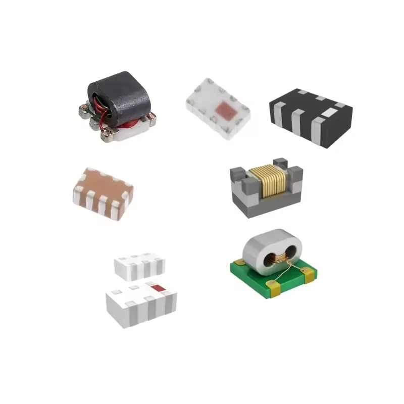
High-frequency RF systems require precision components to maintain stable signal transmission. These components are commonly used in microwave modules, communication equipment, and RF measurement applications.
A directional coupler is an RF measurement component, so electrical verification should be part of the acceptance process.
A common mistake is treating it like a normal passive connector.
The part may have:
- correct dimensions
- correct connector type
- acceptable appearance
but still fail when measured at the operating frequency.
This happens because RF performance depends on more than physical connection.
The actual result can be affected by:
- internal structure
- machining tolerance
- connector alignment
- frequency range
- test setup
For this reason, professional RF evaluation normally includes measurement of the main path and coupled path.
Measure Forward Transmission and Coupled Output Separately
The basic test starts by checking two signal routes.
Main transmission path:
Input Port → Output Port
This measurement shows how much RF energy passes through the coupler.
Typical results include:
- insertion loss
- return loss
- VSWR
The second measurement is:
Input Port → Coupled Port
This verifies:
- coupling value
- coupling flatness
- frequency response
For example, a 20 dB directional coupler should not only be checked at one frequency point.
A component used from DC to 6 GHz may show slightly different coupling behavior at 100 MHz and 6 GHz.
A single measurement point may hide problems that appear during actual operation.
Verify Isolation Between Coupled and Isolated Ports
Isolation is one of the specifications that buyers often overlook.
If forward and reverse signals are not separated properly, the measurement result may not represent the real RF condition.
Use VNA Measurements to Evaluate Complete Coupler Behavior
A vector network analyzer (VNA) is commonly used for directional coupler verification.
Typical S-parameter measurements include:
| Parameter | What It Shows |
| S11 | Input matching and return loss |
| S21 | Main transmission path loss |
| S31 | Coupled port response |
| S41 | Isolation performance |
These measurements help engineers evaluate:
- coupling accuracy
- insertion loss
- VSWR
- isolation
- directivity
For production projects, the test requirement should be defined before mass production.
A useful acceptance record normally includes:
- frequency sweep range
- test equipment
- calibration status
- measurement tolerance
- pass/fail criteria
A supplier and buyer using the same test standard can avoid many unnecessary discussions later.
Directional Coupler Acceptance Test Matrix
A practical acceptance sheet can include:
| Parameter | Inspection Item |
| Frequency Range | Verified operating bandwidth |
| Coupling Factor | Measured coupling value |
| Main Line Loss | Input to output loss |
| Isolation | Separation between ports |
| Directivity | Forward/reverse discrimination |
| VSWR | Reflection measurement |
| Connector Type | SMA / N / BNC / Other |
| Test Equipment | VNA or RF analyzer |
| Result | Pass / Fail |
This type of record is especially useful for OEM projects because the same product may be purchased repeatedly over a long production cycle.
Instead of only checking the part number, engineers can compare actual RF performance against the approved sample.
When Should You Choose a Directional Coupler Instead of a Power Splitter?
The difference between a directional coupler and a power splitter becomes clearer when looking at the system objective.
The question is not:
“Which component has more ports?”
The question is:
“Do we need to distribute the signal or monitor the signal?”
Select a Splitter When Equal Signal Distribution Is the Goal
A power splitter is normally selected when one RF source needs to feed multiple destinations.
Typical applications include:
- antenna distribution
- receiver signal distribution
- multi-channel RF systems
The design target is usually balanced output power.
For example, a 2-way splitter divides one input into two output paths.
Each output receives a portion of the original signal.
Select a Directional Coupler When Monitoring One RF Path Is Required
A directional coupler is used when the main RF signal needs to continue operating while engineers monitor its condition.
Typical applications include:
- transmitter output monitoring
- calibration systems
- RF feedback loops
- production testing
The main path remains active.
The coupled port provides measurement access.
This is especially useful in systems where shutting down the RF path is impossible or inconvenient.
| Requirement | Suitable Component |
| Divide one signal into multiple outputs | Power Splitter |
| Measure signal level during operation | Directional Coupler |
| Reduce signal amplitude | Attenuator |
| Absorb unused RF energy | Dummy Load |
Use Hybrid Couplers When Phase Relationship Becomes Important
A hybrid coupler is another RF component that is sometimes confused with a directional coupler.
The difference is that hybrid couplers are often selected for phase-related applications.
Typical requirements include:
- phase balance
- quadrature output
- balanced RF architecture
Applications may include:
- balanced amplifiers
- beamforming systems
- microwave phase control
The selection depends on whether the system needs signal sampling, power division, or phase control.
How Do You Specify the Right Directional Coupler for a Project?
Many RF sourcing problems begin with incomplete specifications.
A request such as:
“Need SMA directional coupler”
does not define enough information for accurate selection.
A supplier still needs to know:
- frequency range
- coupling value
- power level
- connector type
- application purpose
A clearer specification reduces sample revisions and engineering confirmation time.
Confirm These Parameters Before Requesting a Quotation
A complete RF coupler requirement normally includes:
| Parameter | Example |
| Frequency Range | DC–6 GHz |
| Coupling Factor | 20 dB |
| Directivity | Required dB |
| Isolation | Required dB |
| Main Line Loss | Maximum dB |
| Impedance | 50 Ω |
| Connector Type | SMA |
| Power Handling | Required W |
Additional details may include:
- straight or right-angle connector
- panel mount requirement
- environmental condition
- cable assembly requirement
- inspection standard
These details become more important for custom RF assemblies.
Build a Complete Directional Coupler Requirement Statement
A useful purchasing description could be:
20 dB SMA directional coupler, 50 ohm impedance, DC–6 GHz, low insertion loss, used for RF power monitoring application.
This gives the supplier enough information to evaluate the correct configuration.
A product name alone usually does not contain enough engineering information.
Match Coupler Specifications With the Final Measurement Objective
The coupling factor is only one part of the decision.
A complete evaluation should consider:
- sampled signal level
- measurement instrument range
- operating frequency
- system power
- connector compatibility
- test method
The correct directional coupler is the one that fits the complete RF path.
How Are Modern RF Systems Increasing Demand for Directional Couplers?
RF systems are becoming more complex.
More devices now require continuous monitoring instead of occasional manual testing.
Examples include:
- wireless communication equipment
- microwave modules
- antenna systems
- automated production test platforms
In these systems, engineers need a way to observe signal behavior without interrupting operation.
Support Wider Bandwidth Testing With More Accurate RF Monitoring
Higher-frequency applications create stricter requirements for RF components.
A directional coupler used near microwave frequencies must maintain stable characteristics across the required bandwidth.
Engineers usually evaluate:
- coupling stability
- insertion loss
- isolation
- connector transition quality
The coupler is only one part of the measurement chain.
The final result can also be affected by:
- cable length
- adapter quantity
- connector quality
- installation method
Improve RF Visibility in Complex Signal Chains
Modern RF systems often contain multiple stages.
A typical path may include:
RF source → cable assembly → adapter → directional coupler → amplifier → antenna/load
When unexpected RF behavior appears, engineers need measurement points to locate the problem.
A directional coupler provides that access.
It allows engineers to check signal conditions without repeatedly disconnecting the main RF path.
This is why directional couplers remain common in RF testing, communication equipment development, and production verification.
FAQ
Can I replace a directional coupler with a power splitter?
Not directly. A splitter is intended for signal distribution, while a directional coupler is intended for RF monitoring and sampling.
How should a directional coupler be tested before installation?
The main checks include coupling factor, insertion loss, isolation, directivity, VSWR, and frequency response using suitable RF measurement equipment.
What information should I provide when ordering a directional coupler?
A product name alone is usually not enough for RF applications. Before requesting a directional coupler, it is better to provide the operating frequency, impedance, input power, required coupling value, connector type, and intended use. For example, a coupler used for transmitter monitoring may need different specifications from one used in a laboratory measurement setup. Providing these details early can reduce repeated sample confirmation.
Can I use any directional coupler as long as the connector type matches?
No. The connector only solves the mechanical connection problem. Two couplers with the same SMA interface may have different coupling values, bandwidth, isolation, or power ratings. Before replacement, check the RF requirements of the system, especially the operating frequency and the expected signal level at the coupled port.
Do I need a directional coupler for a simple RF signal split?
Usually not. If the purpose is only sending one RF signal to multiple devices, a power splitter may be the better option. A directional coupler is mainly used when the original signal path needs to continue operating while a small portion of the signal is taken out for monitoring or testing.
Final Practical Note
A directional coupler specification should describe the actual RF requirement, not only the component name.
Before ordering, confirm:
- operating frequency
- impedance
- coupling value
- power level
- connector interface
- measurement purpose
- acceptance test method
For projects operating near the upper frequency limit, the complete RF path should also be considered.
Cable type, adapter transitions, and connector quality can influence the final measurement result.
A clear specification helps engineers reduce substitution risk and helps suppliers provide a configuration that matches the real application.
