
A vehicle roof can look ready for installation until the wrong part reaches the bench. The antenna base threads on, the coax is already attached, and the installer assumes the mount is “NMO” because the product title says so. Then the radio-end connector does not match the radio, the roof hole is the wrong size, or the mount hardware cannot clamp the panel correctly.
That is the expensive part of an NMO mount decision. The mistake is rarely only the mount. It is the mount, antenna interface, cable, connector, roof thickness, and drilling approval being treated as separate small choices.
How do you confirm the mount really matches NMO hardware?
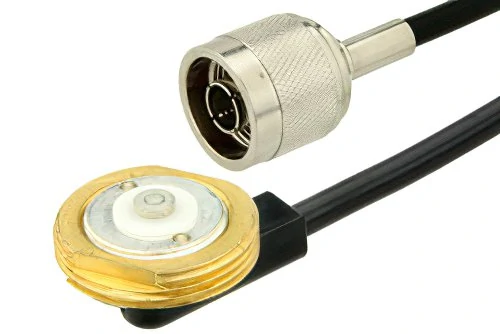
NMO mount cable assembly illustrating how the antenna-side NMO interface connects through coax cable to a separate radio-end RF connector.
Start at the antenna side, not at the radio connector.
For NMO-style hardware, the antenna-side interface is the part that matters first: thread, center contact, mount body, and the way the antenna base seats against the mount. Current PCTEL NMO-style mounts, for example, specify a 3/4-inch hole, 1-1/8″-18 thread, and supported metal thickness for that mount family (PCTEL NMO Style Mounts). That does not make every product in the market identical, but it shows why the drawing matters more than the photo.
Verify the antenna-side thread before looking at the radio connector
A buyer may ask for an “NMO antenna mount” and receive several possible assemblies. Some may be mount-only parts. Some may include cable. Some may ship with the radio connector loose. Some may use a different hole style or panel-thickness range.
Check these fields before releasing the part number:
| Field | What to Confirm |
| Antenna model | The antenna base is intended for the selected NMO interface |
| Mount P/N | Exact manufacturer part number, not only a product-family name |
| Antenna-side thread | Thread and seating geometry match the antenna base |
| Center contact | Contact style and height are compatible |
| Required hole size | Confirmed from drawing or datasheet |
| Roof thickness | Inside the mount’s approved range |
| Cable P/N | Cable type and length are known |
| Radio-end connector | Matches the radio port or test equipment |
| Drawing checked? | Yes / No |
| NMO interface confirmed? | Yes / No |
This card is simple, but it prevents a common sourcing failure: approving a mount by the antenna-side label while ignoring the cable and far-end termination.
Separate the NMO interface from the connector at the far end of the coax
“NMO connector” can be a misleading phrase in purchasing conversations. One person may mean the antenna-side mount interface. Another may mean the complete mount and cable assembly. A third may be asking about the connector that plugs into the mobile radio.
Those are not the same decision.
The antenna end can be NMO while the radio end is SMA, BNC, Mini-UHF, N-Type, TNC, UHF / PL-259, or unterminated cable. TE Connectivity’s NMO through-hole mount documentation lists multiple cable families and radio-side connector options, including BNC, Mini-UHF, N, PL259, SMA, and TNC variants (TE Connectivity NMO Thru Hole Mounts). That is the practical point: the NMO antenna connector and the radio connector must be specified separately.
A safer RFQ line is:
“NMO antenna mount, 3/4-inch hole, RG58A/U cable, 17 ft, terminated with Mini-UHF crimp connector.”
A risky RFQ line is:
“NMO mount with cable.”
The second version leaves too much room for substitution.
Which hole size should you approve before drilling the roof?
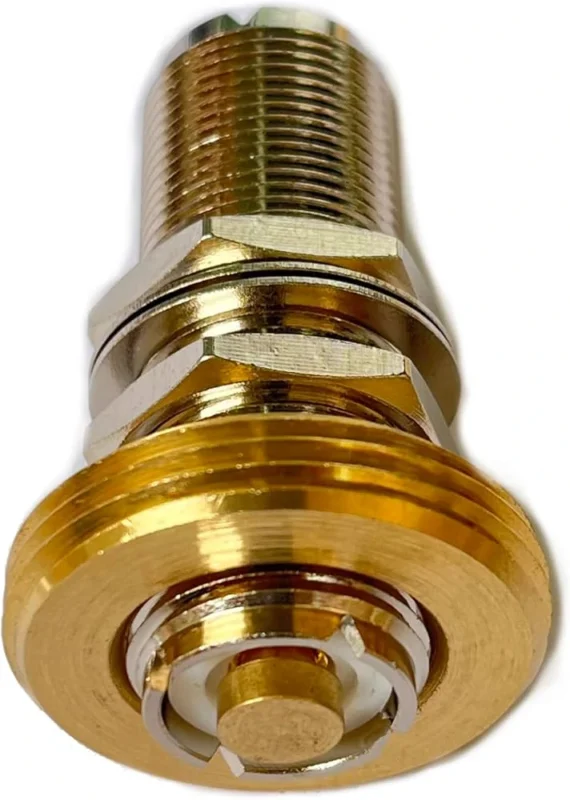
Treat 3/4 inch as common, not universal.
Many NMO roof mount products use a 19.05 mm / 3/4-inch installation hole. That is why installers often talk about a “3/4 NMO mount” as if the hole size were built into the name. It is a useful shorthand in the shop, but it is not a purchasing rule.
TE’s current NMO through-hole catalog also includes 3/8-inch mount families and mounts that support either 3/8- or 3/4-inch openings. Once a vehicle roof is drilled, that assumption becomes permanent. The NMO mount hole size should therefore be approved from the selected part drawing, not from memory, forum advice, or a generic product title.
Check whether the actual mount uses a 3/8-inch alternative
The hole size affects more than the drill bit. It affects the seal footprint, available under-roof access, mount seating, cable exit, and sometimes the way the installer can tighten or service the mount.
Before drilling, confirm:
- Nominal hole diameter
- Allowed tolerance
- Deburring requirement
- Roof or bracket thickness
- Under-roof clearance
- Cable exit direction
- Seal, gasket, or O-ring used with that mount
- Whether the selected part is 3/4 only, 3/8 only, or dual-size
A 3/4-inch hole may be correct for one fleet build and wrong for another mount family ordered under the same broad “NMO” language.
This is not paperwork for its own sake. It protects the vehicle, the installer, and the RF path. A wrong hole can usually be hidden cosmetically, but it is much harder to turn it into a repeatable, sealed, low-risk antenna installation.
How should roof thickness change the mount choice?
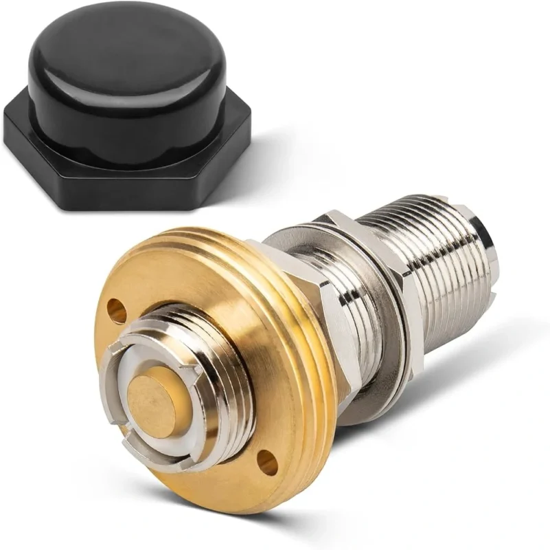
Panel thickness is not a small installation detail. It changes how the mount clamps, how the seal compresses, how the center contact sits, and whether the cable can exit without being forced into a sharp bend.
A standard sheet-metal vehicle roof is not the same as a trunk lid, service-body panel, reinforced roof structure, or bracket. PCTEL’s standard NMO-style mount family, for example, lists use on metal thickness up to 0.046 inch, while TE’s NMO through-hole documentation includes thick-plane configurations for substantially thicker surfaces. The useful rule is simple: approve the mount against the actual measured surface, not against a general “NMO” label.
Match the mounting hardware to the actual sheet thickness
Do not fix a thick roof with extra washers unless the mount drawing allows that arrangement. Washers may help a mechanical fit in some situations, but they do not automatically restore correct thread engagement, center-contact geometry, gasket compression, or RF contact.
This table should be completed before the RFQ is released. If the buyer only specifies “3/4 NMO mount,” the supplier may not know whether the installation surface is thin sheet metal or a thicker plate.
Separate factory roof metal from brackets and reinforced panels
Fleet installations often look similar from outside the vehicle. Under the roof, they can be very different. One vehicle may have easy headliner access and thin factory steel. Another may have a reinforced structure, an equipment rack, thermal lining, or an added service-body panel.
That difference can change the correct mount even if the antenna-side NMO interface stays the same.
This is also where sourcing and installation teams should talk early. The buyer may see one BOM line. The installer sees the roof panel, cable route, nut access, and sealing risk. If those two views are not connected, the wrong mount may pass purchasing review and fail only when the vehicle is already in the bay.
Does the antenna need the vehicle body as its ground plane?
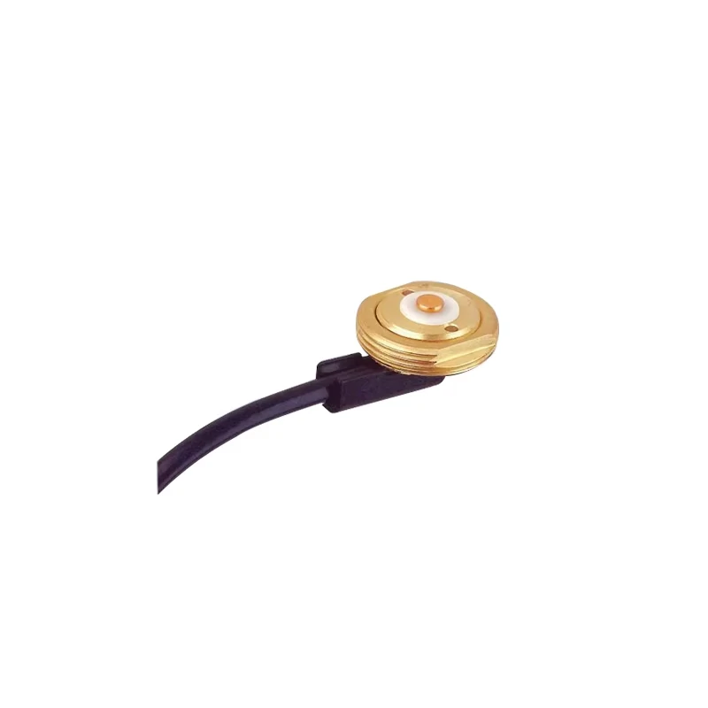
Close-up of an NMO antenna mount with attached coax cable, used for permanent vehicle roof antenna installations and mobile radio systems.
The NMO mount does not decide the ground-plane requirement by itself. The antenna design does.
That distinction matters. Some antennas are designed to use the conductive vehicle body as part of the RF system. Others are ground-plane independent or intended for installations where a traditional metal roof is not available. The NMO ground plane question should therefore be answered from the antenna datasheet, not from the mount name.
Let the antenna design answer the ground-plane question
Avoid the blanket rule that every NMO antenna needs a metal roof. It is too rough for real installations.
For a ground-plane-dependent antenna, the roof is not just a convenient place to attach hardware. It becomes part of the radiating system. Location, surface size, conductivity, bonding, roof accessories, and nearby antennas can all change the installed result.
For a ground-plane-independent antenna, forcing a metal-ground-plane assumption may lead to the wrong product choice or unnecessary installation restrictions.
Do not confuse DC grounding with RF ground-plane behavior
A continuity meter can confirm that two metal points are connected. It cannot prove that the antenna has a good RF ground plane.
That is a common field trap. The installer checks DC continuity, sees a low-resistance path, and assumes the RF installation is healthy. The SWR result later says otherwise. Poor roof location, short conductive area, nearby obstructions, paint or coating at the wrong contact point, and unfavorable cable routing can still affect return loss.
The completed installation must be judged as an RF system: antenna, NMO mount, vehicle surface, coax, radio-end connector, and operating frequency.
How do you choose the cable and radio-end connector together?
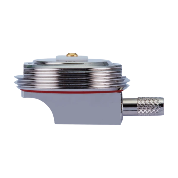
Right-angle NMO antenna mounting assembly with a low-profile cable exit, suitable for vehicle roof and space-constrained mobile radio installations.
The mount and coax should be treated as one assembly. The antenna side may be NMO, but the cable family, length, attenuation, jacket, routing space, and radio-end connector still need separate approval.
TE’s NMO through-hole documentation is a useful reminder here because it lists multiple cable choices such as RG58A/U, RG58U, RG8X, Teflex, Teflon coax, and ATX195, along with different radio-side connector styles including BNC, Mini-UHF, N, PL259, SMA, and TNC (TE Connectivity NMO Thru Hole Mounts).
Match cable loss to frequency before choosing convenience
A short RG58-style vehicle run may be acceptable in many mobile-radio installations. A longer route, higher operating band, tighter bend path, or low-loss requirement can change that decision.
The cable may become the bottleneck before the mount interface does.
Before ordering the finished assembly, record:
| Parameter | Requirement |
| Antenna-side interface | NMO |
| Cable family | RG58A/U, RG58U, RG8X, ATX195, or specified equivalent |
| Cable length | Actual route length, not rough estimate |
| Operating frequency | Highest frequency used in the vehicle system |
| Estimated cable loss | Checked at operating frequency |
| Radio port | SMA, BNC, Mini-UHF, N, TNC, UHF / PL-259, or other |
| Connector orientation | Straight or right-angle |
| First clamp location | Away from mount termination |
| Result | PASS / REDESIGN |
If the vehicle run is tight, also review bend radius and routing practice before finalizing the assembly. TEJTE’s coax cable installation guide can be used as the routing reference rather than repeating all cable-handling rules inside the NMO mount page.
Choose the radio-end connector before ordering the finished mount assembly
The radio-side connector is not an afterthought. A mount assembly with the wrong far-end connector can delay production even if the antenna side is correct.
Specify the connector clearly:
“NMO roof mount, 3/4-inch hole, RG58A/U, 17 ft, Mini-UHF crimp connector.”
If the connector will be installed later, say that too. Some assemblies ship with loose connectors. That may be acceptable for field termination, but it changes inspection responsibility. Crimp quality, solder heat, center-pin seating, and strain relief all move into the installer’s process.
For cable-family comparison outside this mount-specific decision, link buyers to the RG cable guide so this article stays focused on the mount assembly.
Where should an NMO roof mount sit on the vehicle?
The best location is not always the easiest place to drill.
For a ground-plane-dependent antenna, start with RF symmetry and the available conductive surface. Then check physical clearance, roof racks, light bars, other antennas, interior access, headliner removal, cable route, and serviceability.
Score each candidate location before drilling:
| Factor | 0 | 1 | 2 |
| RF symmetry | Poor | Acceptable | Strong |
| Obstruction clearance | Poor | Moderate | Clear |
| Cable route | Difficult | Manageable | Direct |
| Interior access | Poor | Limited | Easy |
| Water-management risk | High | Medium | Low |
| Service access | Poor | Moderate | Good |
A total score of 0–4 means redesign the location. A score of 5–8 means review the compromise. A score of 9–12 is a strong candidate.
This is not an industry standard. It is a practical screening tool for installers and buyers who need one shared way to compare roof positions before the drill touches the vehicle.
When is a permanent roof mount better than a magnetic mount?
A permanent NMO roof mount makes sense when the vehicle is part of a controlled fleet build. The antenna location is repeatable, the cable entry is planned, and the coax is not left exposed across the roof edge or door seal.
A magnetic mount has a different job. It is useful for temporary radio use, rental vehicles, test work, and installations where drilling is not allowed. It should not be selected only because it feels easier. The RF behavior can change with the mounting surface, cable path, ground-plane condition, and antenna design.
For permanent service vehicles, public-safety builds, industrial fleets, and long-term mobile-radio systems, the drilled NMO mount usually gives the cleaner installation. For short-term deployment, a magnetic option may be the lower-risk choice.
How should water sealing and corrosion be controlled after installation?
The roof penetration is both a mechanical opening and an RF interface. Treat it that way.
Check the gasket, O-ring, mount seating, roof surface, paint condition, and cable exit before the vehicle leaves the shop. Do not add random grease, paint, or coating between electrical contact areas unless the mount manufacturer allows it. Corrosion control is useful only if it does not damage the required RF or mechanical contact.
A simple post-install inspection should include:
| Check Item | Pass Condition |
| Exterior mount seating | Flush, stable, no visible tilt |
| Gasket / O-ring | Correct part, evenly compressed |
| Roof surface | Clean, deburred, no loose paint at sealing area |
| Interior penetration | No water path, no metal debris left inside |
| Cable strain relief | Cable supported, no pull load on mount |
| First bend | Not forced directly at the mount termination |
| Water inspection | No leak after controlled water check |
Cable routing matters here. If the coax is pulling on the underside of the mount, the seal can become a mechanical stress point. The cable should be supported early, with a serviceable path that does not trap water or crush the jacket behind trim.
Build the RF acceptance plan before the vehicle leaves the shop
Do not release the vehicle after only a visual check.
The final RF test should represent the installed system: antenna, NMO mount, roof or bracket surface, coax, radio-end connector, and operating band. A loose bench test does not include the same ground-plane geometry, cable bends, or nearby vehicle structures.
Modern NMO hardware should not automatically be treated as only a traditional VHF/UHF mobile-radio part. TE currently lists a high-performance NMO mount datasheet covering 0–6000 MHz for its NMOHPC family, and current distributor listings also show high-frequency NMO roof-mount kits specified for 0–6000 MHz (TE Connectivity NMOHPC product page, Tessco NMOKHFUD25 listing). That does not mean every NMO mount supports 6 GHz. Approve frequency from the exact mount P/N and cable assembly.
How should a weak SWR result be diagnosed after installation?
Do not replace the antenna first.
Split the signal path into sections:
- Antenna
- NMO contact
- Roof or ground-plane condition
- Coax
- Radio-end connector
- Radio port
A weak SWR result may come from poor antenna-to-mount contact, paint or coating at the wrong contact area, pinched coax, a damaged radio-end connector, or a ground-plane mismatch. If the reading changed after trim was installed, inspect the cable route before blaming the antenna.
| Symptom | First Check | Second Check | Likely Area |
| High SWR immediately | Antenna / mount mate | Ground plane | Interface |
| SWR changes when cable moves | Cable route | Radio connector | Cable |
| Good before trim installation | Pinch points | Bend locations | Routing |
| Intermittent signal | Center contact | Cable termination | Mechanical |
| Water-related change | Roof seal | Connector corrosion | Environment |
A known-good substitution test can help, but only if the substitute antenna, mount condition, and test frequency are controlled. Otherwise, the test only adds another variable.
Specify the NMO mount as a complete assembly, not a loose part
The final RFQ should not say only “NMO mount with cable.” That phrase is too open.
Use a controlled configuration:
“NMO antenna mount, 3/4-inch hole, approved for measured roof thickness, RG58A/U cable, 17 ft, terminated with Mini-UHF crimp connector, gasket included, SWR checked at target frequency.”
If the installation uses a separate radio connector, adapter, or custom coax route, the RF connector guide can support the connector-side decision while this page remains focused on the vehicle mounting system.
FAQ
How do I know whether my NMO mount really requires a 3/4-inch hole?
Check the exact mount drawing before drilling. Many NMO mounts use a 19.05 mm / 3/4-inch opening, but 3/8-inch and dual-size mount families also exist. “NMO” identifies the antenna-side mounting interface, not one universal roof-drilling dimension.
Does every NMO antenna need a metal roof as a ground plane?
No. The requirement belongs to the antenna design. Some antennas use the conductive vehicle body as part of the RF system, while other designs are ground-plane independent. Confirm the antenna datasheet before forcing a metal-roof requirement into the installation plan.
Can the same NMO antenna mount use different connectors at the radio end?
Yes, depending on the mount and cable assembly. The antenna side can be NMO while the radio end uses SMA, BNC, Mini-UHF, N, TNC, UHF / PL-259, or an unterminated cable. Specify both ends clearly.
Where should an NMO roof mount be placed on a vehicle?
Start with the antenna’s RF requirement, then check roof symmetry, conductive surface where required, obstructions, cable route, under-roof access, and sealing risk. The easiest drilling location is not automatically the best installed RF location.
Can an NMO mount work above traditional VHF and UHF bands?
Some current products can, but not all. Use the frequency rating of the exact mount P/N and complete cable assembly. The cable type, cable length, connector termination, and installed routing can limit performance before the mechanical mount does.
Why did SWR become worse only after installation?
The completed vehicle installation adds variables that a bench test may not include: ground-plane geometry, antenna-to-mount contact, cable bends, pinched coax, connector termination, and nearby roof structures. Troubleshoot the finished RF path one section at a time.
Should I choose a permanent or magnetic NMO mount?
Choose based on the installation requirement. A permanent NMO roof mount suits fixed fleet builds with controlled antenna location and cable entry. A magnetic mount is better for temporary use or vehicles that cannot be drilled. Ground-plane and cable behavior still need verification.
