
A blue automotive coax connector arrives on the sourcing desk. The supplier calls it a “GPS FAKRA,” the vehicle harness drawing shows Code C, and the sample appears to fit.
That still is not enough information to approve it.
A FAKRA connector has to be identified as a complete interface: coding key, housing, plug or jack configuration, center contact, cable termination, orientation, and mating part. Color helps, but color by itself is a poor purchasing specification. Two parts can look close enough in a photo and still belong to different keyed interfaces.
This is where automotive RF sourcing often goes wrong. The sample is ordered from appearance first, and the drawing is checked later.
How do you decode a FAKRA housing before choosing the connector?
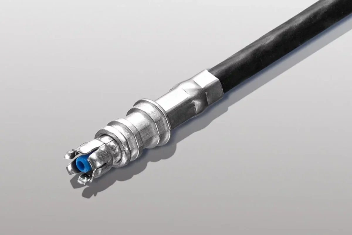
Start with the mechanical identity of the connector.
For purchasing purposes, “blue FAKRA,” “green FAKRA,” or “GPS connector” is incomplete language. A useful identification record should include at least:
- coding letter;
- mechanical key;
- housing color;
- plug or jack configuration;
- center-contact configuration;
- straight or right-angle cable exit;
- cable-mounted or PCB-mounted construction;
- single, dual, or multi-position housing;
- mating connector part number.
The coding letter deserves first attention because the plastic housing is part of the error-proofing system. Current FAKRA product references commonly identify keyed versions including A, B, C, D, E, F, G, H, I, K, L, M and N, with Z used as a neutral coding configuration.
Read mechanical keying before relying on housing color
Color is useful on an assembly line because it gives an immediate visual cue. It is not a substitute for the mechanical key.
A common shortcut is:
Blue housing = GPS, so another blue connector should work.
That shortcut creates risk.
Vehicle manufacturers can use several RF paths in the same area: GNSS, AM/FM, satellite radio, telematics, cellular antennas or other coaxial connections. The safest approval method is to compare the connector against the vehicle drawing or the approved mating part, not against a color photograph.
If an incoming sample has no readable part number, inspect the key position and mating geometry before placing a production order.
Keep connector identity separate from vehicle function
Another sourcing trap is allowing the application name to become the connector specification.
“FAKRA GPS connector” may be useful as a search phrase, but it is not enough for a BOM. The same navigation system still needs a defined code, interface gender, cable group, orientation and mating connector.
A buyer should be able to hand the specification to a second supplier without sending a reference photo and asking, “Can you make this one?”
A more useful BOM description looks like this:
FAKRA Code C, jack, right-angle cable version, 50 Ω, specified cable group, mating connector P/N confirmed.
The exact wording can vary by company. Consistency matters more. Pick one naming convention and use it across drawings, RFQs, incoming inspection records and production labels.
Build a FAKRA Connector Identity Card before approving samples
For projects with several automotive coax ports, a small identification record prevents surprisingly expensive mistakes.
This record is more useful than a folder of product photos. It also gives incoming inspection a reference when the supplier changes a housing mold, cable source or subcomponent..
Which FAKRA codes can mate—and when does Z code change the decision?
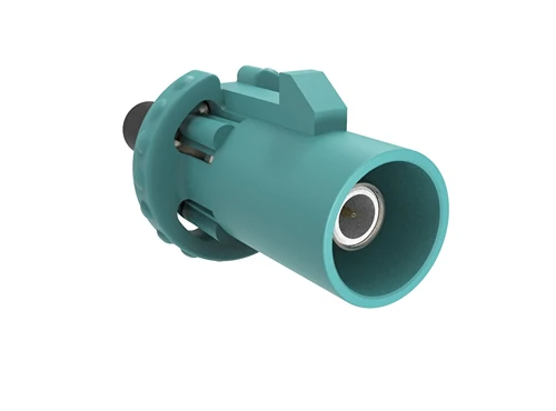
Detailed view of a single-position FAKRA coax connector showing its color-coded housing, mechanical keying and RF center-contact interface.
Keyed FAKRA connectors are meant to reduce incorrect mating. That advantage disappears if procurement treats every housing as interchangeable.
The practical rule is simple: do not force two keyed connectors together because the RF contact inside looks similar.
The coding system exists specifically to distinguish interfaces that may otherwise look very close on a wiring harness.
Separate keyed FAKRA codes from neutral Z coding
Z code requires a separate sourcing decision.
In the referenced FAKRA coding material, Z is identified as a neutral coding rather than another ordinary keyed color position. This gives it broader mechanical flexibility, which can be useful during testing, service work or specific harness designs.
That flexibility can also remove part of the mistake-proofing benefit.
If a production module has GNSS, radio and telematics coax ports positioned next to one another, using application-specific keyed housings can help prevent an operator from connecting the correct cable to the wrong port.
A connector that fits more interfaces is not automatically the safer production choice.
Keep keyed connectors where poka-yoke matters
Keyed coding becomes especially useful when several RF connectors are concentrated in one assembly.
Examples include:
- combined navigation and telematics modules;
- antenna control units;
- multi-antenna roof modules;
- infotainment equipment;
- production harnesses with several nearby coax branches.
In these cases, mechanical coding becomes part of the manufacturing control system, not merely a connector feature.
A good supplier substitution therefore needs to answer two different questions:
- Will the connector physically mate?
- Does the replacement preserve the intended error-proofing strategy?
Those are not always the same decision.
Use a coding compatibility record instead of relying on memory
The color column helps identification. The Mate Verified column is the one that should release the BOM.
That distinction matters when replacing an existing FAKRA coax connector or approving a second source. Procurement should not assume that “same color,” “same application,” or even “physically mates” means that the connector is equivalent for production.
How do you distinguish FAKRA male and female without trusting the product title?
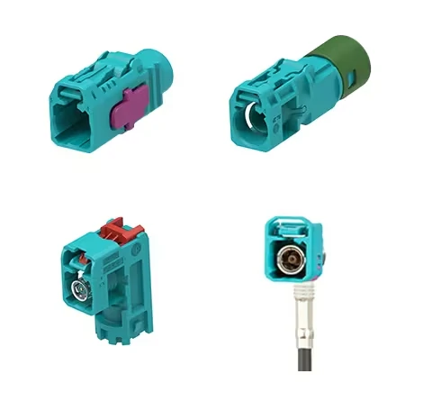
Examples of keyed FAKRA connector configurations, including straight cable, right-angle cable and PCB-mounted versions used in automotive RF systems.
FAKRA gender becomes confusing when three vocabularies appear on the same quotation.
One supplier writes male / female. Another uses plug / jack. A drawing may describe the RF contact as pin / socket. If those terms are copied into a BOM without checking the actual interface, the purchasing description can contradict the drawing.
Product titles are especially risky. A listing called “FAKRA female connector” may be referring to the housing, the center contact, or simply the supplier’s own naming convention.
Identify the complete mating interface
For sample approval, record four items separately:
- housing role;
- center-contact style;
- plug or jack designation;
- approved mating connector.
Do not decide gender from the plastic shell alone.
The useful question is not “Does this look male?” but:
Which exact interface does this connector mate with in the vehicle?
That approach becomes even more important when cable-mounted and PCB-mounted parts are mixed in the same project. A cable harness may terminate at a straight or right-angle PCB FAKRA connector, while an inline harness joint uses a different housing construction.
Keep housing gender separate from center-contact language
This is a small BOM discipline that prevents large sourcing errors.
If the company standard uses “plug” and “jack,” keep using those terms. If it uses “male housing” and “female housing,” define exactly what that means on the drawing.
Avoid mixing all three systems in one description:
FAKRA male plug female socket connector.
That may be understandable to the original engineer, but it is poor information for a second-source supplier.
A cleaner record looks more like:
FAKRA Code C, jack interface, socket contact, right-angle cable mount, mating P/N XXXXX.
The exact terminology can follow your company standard. The drawing should remove any remaining ambiguity.
A table like this is useful during supplier change, prototype approval and incoming inspection because it forces the team to confirm both sides of the connection.
Which cable construction belongs behind the FAKRA housing?
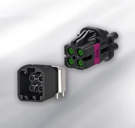
Close-up of a multi-position automotive coax connector with four RF ports, mechanical keying and a secondary locking structure for high-density vehicle wiring systems.
The front housing does not tell you which coax belongs behind it.
That distinction is easy to miss because buyers often search for a complete FAKRA cable by application name—GPS, antenna, telematics—and assume the connector code determines the cable.
It does not.
A FAKRA code manages mechanical mating and identification. Cable compatibility is controlled at the rear termination.
Match the coax dimensions, not just the connector code
Before approving a FAKRA coax connector, check:
- impedance;
- cable outside diameter;
- dielectric diameter;
- shield construction;
- shield diameter;
- center conductor size;
- jacket material;
- required temperature range;
- rear termination design.
A contact and ferrule made for a miniature coax should not automatically be used on a larger cable simply because the front FAKRA housing is identical.
This is the same sourcing problem seen across ordinary RF connectors: the mating face can be correct while the cable-side geometry is wrong.
A cable may still pass continuity after a poor substitution. That does not prove that braid contact, center-conductor retention or RF behavior is acceptable.
Keep cable group and FAKRA code as two separate selections
A useful engineering rule is:
Code C does not define the coax.
The same FAKRA coding family may be assembled with different supported cable groups depending on the connector design. The outline specifically treats RG178/RG196, RG316/RG174 and RG58-class constructions as examples of different cable groups that may appear within FAKRA product systems.
That means an RFQ should never stop at:
Blue FAKRA, 1 meter.
At minimum, add the exact cable P/N or an approved cable specification.
This table becomes particularly useful when the supplier proposes a “similar” cable because the original part is unavailable. Similar OD does not mean identical shielding, attenuation, temperature capability or crimp behavior.
How should a GPS or GNSS design use FAKRA without relying on color alone?
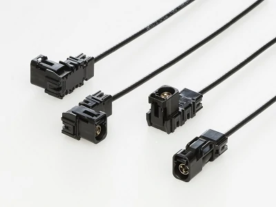
A selection of compact automotive coax cable assemblies with straight and right-angle connector configurations for high-density RF and high-speed vehicle applications.
Automotive navigation is one of the most common places buyers encounter a FAKRA GPS connector, but “GPS” still should not become the connector specification.
Map the RF path first.
A typical arrangement may look like:
Roof or shark-fin antenna → FAKRA cable → vehicle harness → GNSS receiver or telematics module
Every point in that path needs to agree on interface, impedance and system requirements.
Check the complete navigation path
For the cable assembly, confirm:
- FAKRA code;
- connector gender;
- cable type;
- cable length;
- antenna type;
- module interface;
- routing conditions;
- any inline connection.
If the system uses an active GNSS antenna, another question appears: does DC bias travel on the same coax?
The RF connector may be mechanically correct while the complete assembly is still wrong for the powered antenna path.
Confirm:
- bias supply from the receiver;
- DC continuity through the intended coax path;
- inline filters;
- amplifiers;
- splitters or other components that may block DC.
Keep nearby vehicle RF ports error-proofed
A telematics unit may place GNSS, cellular, AM/FM or satellite-radio coax ports close together.
In that situation, four things should work together:
- FAKRA mechanical code;
- housing color;
- harness label;
- physical harness routing.
Removing one layer of identification may not cause an immediate electrical fault. It can instead create an assembly-line mistake that appears only after the vehicle is built.
For production teams, this is often more useful than a general connector chart because it links the physical connector to the actual vehicle function.
How do you keep the full automotive RF path at the intended impedance?
A correct FAKRA housing cannot rescue a poorly specified RF path.
The complete chain should be audited:
RF module → PCB connector → cable contact → coax → inline connector → antenna
Any adapter or additional joint belongs in the same review.
Audit more than the plastic housing
For a nominal 50 Ω system, check the impedance specification of every RF element rather than assuming that matching FAKRA codes prove electrical compatibility.
The article outline uses ISO 20860-1 as the interface baseline for the road-vehicle 50 Ω RF connection system. The practical point for sourcing is straightforward: mechanical coding and electrical compatibility are related checks, but they are not the same check.
Two connectors can share the correct mechanical code while the finished assembly still has problems caused by:
- unsuitable coax;
- poor termination;
- excess cable length;
- damaged braid;
- tight bending;
- additional adapters;
- inconsistent assembly.
Decide straight or right-angle only after mapping harness routing
A right-angle FAKRA connector is not automatically the better choice in a tight module.
Sometimes it removes an immediate bend. Sometimes it simply moves the interference to another direction.
Map the harness before locking the connector orientation.
Use a straight exit when there is enough axial depth and the cable can enter its normal bend radius without pressing against the enclosure. A right-angle version becomes useful when the module sits close to a wall, cover, PCB or neighboring connector.
Check four items before approval:
- rear clearance;
- side clearance;
- cable bend radius;
- access to the locking feature.
The FAKRA code does not define cable exit direction. The same code may appear in straight, right-angle, cable-mounted and PCB-mounted versions.
How should locking engagement be verified on the assembly line?
An electrical connection can exist before the housing is fully locked.
That is why continuity alone is a weak acceptance test for mating quality.
During assembly, verify:
- correct FAKRA code;
- full housing seating;
- primary latch engagement;
- secondary locking feature where specified;
- no cable side load;
- no cracked or deformed housing;
- retention after mating.
Do not make the audible “click” the only acceptance criterion. Operators should have a visual or mechanical reference for full engagement.
The outline also distinguishes conventional FAKRA locking from newer connector systems that may use additional Connector Position Assurance mechanisms. That feature should only be specified where the actual connector design includes it; it should not be generalized to every FAKRA housing.
When should standard FAKRA give way to Mini-FAKRA or HFM?
Do not replace standard FAKRA simply because a smaller connector is available.
For conventional automotive antenna, GNSS, radio and telematics connections, standard FAKRA may remain entirely adequate when packaging space and bandwidth allow it.
Miniaturized high-speed coax systems become more relevant when the architecture is driven by:
- higher connector density;
- higher data rate;
- camera or SerDes links;
- reduced PCB area;
- tighter module packaging.
The source outline notes HFM-class systems as a higher-speed, smaller automotive coax option and specifically warns that they are not drop-in replacements for standard FAKRA. Interface geometry, PCB footprint, cable, coding and qualification all need to be reconsidered.
| Requirement | Standard FAKRA | Mini-FAKRA / HFM |
| Traditional RF antenna | Strong fit | Usually unnecessary |
| GNSS / telematics | Common fit | Architecture-dependent |
| Camera / high-speed data | Limited by system design | More relevant |
| Connector density | Larger footprint | Better fit |
| Existing harness replacement | Easier | Redesign likely |
| New vehicle platform | Viable | Evaluate when bandwidth/density justify it |
A smaller connector is an architecture decision, not an automatic upgrade.
Validate a complete FAKRA cable assembly instead of approving the housing alone
A finished harness should be tested as an assembly.
Start with mechanical and wiring checks:
- correct code and housing;
- correct gender;
- correct cable P/N;
- continuity;
- shield continuity;
- no center-to-shield short.
For RF-critical assemblies, add VNA measurements such as insertion loss and return loss at the required frequency range.
The outline also recommends comparing the cable in its free state with the final routed condition because clipping, bending and installation stress can change the result.
A useful comparison is:
ΔIL = IL installed − IL free
If installed insertion loss is noticeably worse, investigate cable bends, connector stress, routing or termination before blaming the connector series.
Build a supplier specification that prevents coding mistakes
“Blue FAKRA cable, 1 m” is not a production RFQ.
A better supplier record should define:
- FAKRA code;
- plug / jack;
- center contact;
- straight / right-angle;
- cable or PCB mount;
- exact coax P/N;
- impedance;
- length;
- frequency requirement;
- locking requirement;
- environmental requirement;
- test requirement;
- packaging label.
Where relevant, also lock the housing, RF contact, cable and assembly instruction as one approved combination.
A practical description could read:
FAKRA Code C, jack, right-angle cable version, 50 Ω, approved coax P/N, specified cable length, mating P/N confirmed, continuity and RF inspection per project requirement.
That description is much harder to misunderstand than an application name alone.
How should incoming lots be screened without checking every characteristic every time?
Not every characteristic needs 100% inspection.
Coding errors usually deserve the strictest control because the wrong housing can stop assembly immediately or create a misrouting risk.
A practical lot plan is:
| Characteristic | Method | Suggested Control |
| Coding | Visual / key fixture | 100% |
| Housing color | Visual | 100% |
| Gender | Visual / mating sample | 100% |
| Orientation | Visual | 100% |
| Locking | Mating fixture | Sample |
| Cable retention | Pull test | Risk-based |
| Continuity | Electrical test | Defined plan |
| Insertion loss | VNA | Risk-based |
| Return loss | VNA | Risk-based |
The exact sampling level belongs to the project quality plan. The useful principle is to separate obvious assembly-stop errors from slower RF process drift.
If RF results start moving, expand the sample and investigate the process rather than continuing to release lots based only on visual inspection. The outline specifically treats coding, retention, continuity and RF measurements as different incoming-control layers.
FAQ
How can I identify the exact FAKRA code when the vehicle drawing is unavailable?
Record the housing color, mechanical key position, plug/jack configuration, cable exit direction and any readable connector P/N. Compare those details with a verified coding reference or mating sample. Do not order a replacement based only on color when the mechanical code remains uncertain.
Does matching the FAKRA housing color guarantee compatibility?
No. Color is an identification aid. Mechanical coding, gender and the actual mating interface still need to match. Two parts that appear similar should not be considered interchangeable until the key and mating configuration are confirmed.
Can a Z-code FAKRA connector replace every keyed connector?
No. Z is treated as neutral coding, which can provide broader mating flexibility, but that flexibility may remove some of the error-proofing provided by application-specific keyed connectors. Production harness requirements still need to be considered.
Does the FAKRA code determine which coax cable must be used?
No. FAKRA coding primarily addresses mechanical mating and identification. Cable selection still depends on impedance, conductor and dielectric dimensions, shielding, OD, temperature requirement and the connector’s supported rear termination.
Can two vehicle RF functions use connectors that look nearly identical?
Yes. Similar color, shape or size does not prove that two ports serve the same function. Vehicle drawings, FAKRA coding, harness labels and mating P/Ns should be used together when identifying GNSS, radio, telematics or other RF connections.
When should a design move from standard FAKRA to Mini-FAKRA or HFM?
Evaluate a miniaturized system when higher data rate, higher connector density or packaging constraints become dominant. Do not treat it as a direct replacement. The PCB footprint, cable, interface, qualification and harness architecture may all change.
Should a FAKRA cable assembly be tested again after harness installation?
For RF-critical paths, prototypes or projects where routing changes significantly, comparing the free cable with its installed condition can reveal loss or mismatch caused by tight bends, connector loading or harness installation. Continuity alone cannot show those RF changes.
Final buying guidance
The easiest FAKRA mistake is buying from appearance.
The safer sequence is:
Confirm code → verify mating interface → define gender → match the coax → check routing → confirm locking → test the finished assembly → release the BOM.
For RF engineers, that sequence protects the signal path.
For procurement teams, it prevents a supplier from substituting a connector that looks correct but differs in coding, termination or cable compatibility.
For production, it turns FAKRA identification from a color-matching exercise into a controlled assembly specification.
If a supplier is being asked to quote a complete FAKRA cable assembly, send the FAKRA code, mating connector, cable type, cable length, orientation, frequency requirement and inspection target together. That information is far more useful than sending a photo marked “same as this.”
