
A bulkhead connector can look correct in the purchasing photo and still fail at the panel.
The usual problem is not the SMB mating end. It is everything behind it: the threaded barrel is too short for the finished enclosure, the shoulder does not pass through the cutout, the rear body collides with a PCB, or the connector sold as an “SMB female bulkhead” is not the interface the equipment actually needs.
That is why an SMB bulkhead connector should be specified as a complete mechanical and RF interface, not as a connector name plus a panel hole.
For a prototype, the mistake may cost one enclosure. In production, the same mistake can leave hundreds of punched or machined panels waiting for rework.
Which SMB bulkhead interface belongs on the panel?
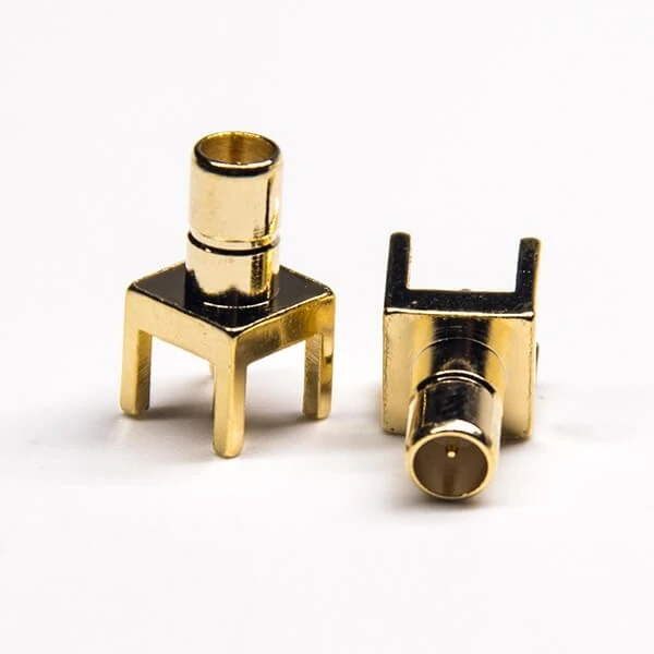
Two views of an SMB PCB mount connector featuring a four-leg through-hole structure for stable board installation.
Start with the interface that must mate outside the enclosure. Do not start with the supplier’s male/female title.
SMB naming creates more purchasing errors than it should because several descriptions can appear in catalogs: plug, jack, male, female, pin, socket, receptacle, panel mount, bulkhead, cable type, and PCB type. Two parts may both contain “SMB female” in a listing while their mounting or rear termination is completely different.
A useful purchasing record separates those functions before a part number is approved.
Confirm plug, jack, pin, and socket separately
Record the external SMB interface first. Then confirm the center contact by looking at the approved drawing or a clear front-interface photograph.
The RFQ should also identify:
- the mating equipment port;
- SMB plug or jack configuration;
- center pin or socket;
- nominal impedance;
- panel, PCB, or cable mounting;
- rear termination method;
- internal coax family.
This prevents a common sourcing shortcut: approving a connector because the shell appears to mate while nobody has checked the contact arrangement and rear geometry.
If the project team is still identifying the interface family, use the existing TEJTE SMB Connector Guide as the general SMB reference rather than repeating that basic identification work in the BOM. The present guide is narrower: it is concerned with making the selected interface physically work through a chassis.
Give the SMB female bulkhead configuration its own check
An SMB female bulkhead connector or SMB jack bulkhead connector should not be approved from the word “female” alone.
Check the mating face, center contact, mounting barrel, hardware, and rear termination together. If the connector must pass through the enclosure and terminate to a small coax inside, the rear construction matters just as much as the front jack.
This becomes especially important when purchasing from multiple suppliers. A replacement may mate with the same SMB plug yet use another shoulder diameter, usable thread length, ferrule, solder post, or anti-rotation feature.
For production sourcing, interface compatibility is only the first gate. Mechanical interchangeability must be checked separately.
Separate panel-mount SMB from PCB-mounted SMB
A PCB connector that sits near an enclosure opening is not automatically an SMB panel mount connector.
PCB versions may rely on board solder joints for mechanical support. A true chassis-mounted arrangement transfers external mating and cable loads into the enclosure. Mixing those architectures can put repeated insertion force onto the PCB or solder joints.
The distinction matters most when the external cable is frequently disconnected. The panel should support the connector if the panel is intended to carry that mechanical load.
TEJTE’s broader RF connector selection material also treats mounting style, cable compatibility, frequency, and impedance as separate selection factors rather than a single connector-name decision.
A simple interface record can stop that confusion before samples are ordered.
| Required Field | Buyer Entry |
| Mating equipment | |
| SMB interface | Plug / Jack |
| Center contact | Pin / Socket |
| Impedance | |
| Mounting style | Bulkhead / PCB / Cable |
| Rear termination | Crimp / Solder / Other |
| Cable family | |
| Drawing reference | |
| Front photo | |
| Rear photo |
Keep this record with the drawing revision. If a supplier proposes a substitute later, compare the substitute against the record instead of comparing product titles.
How should the panel cutout be derived from the actual connector drawing?
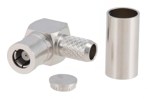
A right-angle SMB crimp connector with separate ferrule and rear component, suitable for compact coaxial cable routing.
Do not send the enclosure supplier a hole diameter based on “standard SMB size” and expect every bulkhead part to fit.
The safer workflow runs in the opposite direction:
Approved connector drawing → mounting geometry → manufacturing tolerance → finished panel cutout.
The specific connector controls the hole.
Start with the thread and shoulder geometry
The threaded barrel is only one dimension in the mounting path. Review the complete profile that must pass through, sit against, or clear the panel.
At minimum, check:
- thread major diameter;
- body or shoulder diameter;
- anti-rotation flat;
- washer outside diameter;
- nut outside diameter;
- rear-body clearance;
- ferrule or solder termination clearance;
- tool access around the nut.
A drawing review should also establish which surface actually seats against the chassis. Otherwise, the cutout may clear the thread but stop against a larger shoulder before the connector reaches its intended mounting position.
Avoid publishing one universal SMB mounting-hole diameter
Searches for SMB bulkhead mounting hole size often imply that there should be one number. That is not a safe production assumption.
The panel opening depends on the actual bulkhead construction. One part may use a circular threaded section. Another may add flats or a feature intended to resist rotation. Hardware and mounting direction can also change the required clearance.
For that reason, a general guide can explain how to calculate the cutout, but the production drawing should always reference the approved connector part number and revision.
This also makes supplier substitution easier to control. If a proposed alternative changes the mounting dimensions, procurement can identify the change before the enclosure is released.
Include tolerance, plating, and coating in the cutout review
A nominally correct metal opening can become a poor fit after finishing.
Powder coating, paint, anodizing requirements, burrs, punching variation, and CNC tolerance all affect the finished mounting condition. The drawing therefore needs to describe the finished panel, not only the raw sheet.
Do not solve a tight fit during assembly by forcing the connector through the opening. That can damage the finish, alter the grounding contact area, or place unnecessary stress on the body.
For first-article approval, use a small cutout sheet rather than waiting for the finished enclosure whenever practical. It is faster to revise one test coupon than a complete chassis.
A useful approval record is:
That table should be completed before the panel drawing is frozen. The next check is more easily missed: even with the correct cutout, the connector can still be unusable when the enclosure wall, coating, gasket, and washer stack consume too much of the available thread.
How thick can the enclosure wall be before thread engagement becomes marginal?
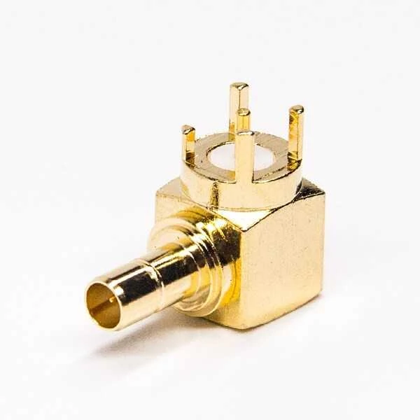
Gold-plated right-angle SMB PCB connector with multiple solder legs for board retention and low-profile RF routing.
A panel hole can be correct and the connector can still fail to mount.
The next limit is the complete mounting stack.
For an SMB bulkhead connector, the chassis thickness is only one part of that stack. Paint, anodizing, sealing material, flat washers, lock washers, and other hardware all consume part of the threaded barrel. A connector that fits a bare 1.5 mm test plate may become marginal after the production enclosure receives its final surface treatment and hardware.
Calculate the complete mounting stack instead of panel thickness alone
The review should include every layer between the connector shoulder and the locking nut:
- bare chassis thickness;
- paint or coating;
- EMI gasket if used;
- sealing washer;
- flat washer;
- lock washer;
- any insulating spacer;
- required nut engagement.
The useful question is not:
“What is the panel thickness?”
It is:
“How much usable thread remains after the finished mounting stack is installed?”
A practical first-pass calculation is:
Usable Thread Length = Threaded Barrel Length − Panel Stack Thickness
For a more detailed review:
Lusable = Lthread − Tpanel − Tcoating − Tgasket − Twasher
Where:
- Lthread = usable threaded barrel length;
- Tpanel = enclosure wall thickness;
- Tcoating = finished coating contribution;
- Tgasket = gasket or sealing stack;
- Twasher = washer or spacer stack.
The remaining length still has to provide enough thread for the selected nut and the supplier’s required mechanical engagement.
Do not invent a universal minimum engagement value in the BOM. Use the actual connector drawing, nut geometry, supplier requirement, and project mechanical acceptance criteria.
Check rear clearance as well as front-side engagement
More thread is not automatically better.
A long rear barrel may solve one panel-thickness problem and create another inside the enclosure. It can interfere with:
- the PCB edge;
- a shielding can;
- a nearby module;
- cable ferrule clearance;
- soldering access;
- cable bend radius;
- service-tool access.
That is why the mechanical drawing should show both sides of the panel.
One dimension describes how the connector locks to the chassis. Another describes how far the complete assembly extends into the equipment.
This becomes especially important in compact wireless devices where the SMB bulkhead sits only a few millimeters from the PCB.
For repeat production, put an approved panel range on the controlled drawing rather than writing only “for panel mounting.”
A stronger note is:
Approved finished panel stack: X–Y mm, including specified coating and washer stack.
That gives purchasing and production something measurable.
Should the connector be front-mounted or rear-mounted?
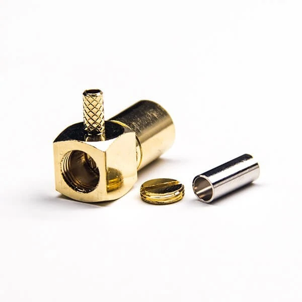
An exploded view showing the body, center contact, ferrule and rear hardware used to assemble a right-angle SMB coaxial cable connector.
Front and rear mounting can produce similar-looking finished equipment, but the assembly sequence is not the same.
The better choice depends on tool access, exterior profile, cable preassembly, maintenance requirements, and how the connector will be replaced later.
Use front mounting when service access is more important
Front mounting can simplify replacement on:
- test fixtures;
- prototype enclosures;
- replaceable panels;
- serviceable RF equipment;
- laboratory setups.
It may allow the technician to reach the connector hardware without dismantling as much of the internal assembly.
The trade-off is appearance and external hardware exposure. The nut or mounting structure may remain more visible depending on the connector design.
Choose rear mounting when the exterior profile must stay cleaner
Rear mounting is often useful when the equipment designer wants a cleaner exterior surface.
But that visual benefit comes with practical questions:
- Can the nut be reached after the PCB is installed?
- Must the cable be attached before the connector enters the chassis?
- Can the assembly be removed without taking out another module?
- Is there enough space for a wrench or fixture?
- Can the rear body pass through the required opening?
These should be answered before freezing the enclosure drawing.
A useful production comparison is:
| Requirement | Front Mount | Rear Mount |
| Exterior profile | Hardware may be more visible | Often cleaner |
| Nut accessibility | Often easier | Enclosure-dependent |
| Replacement access | Usually simpler | May require internal access |
| Cable preassembly | Design-dependent | Often more important |
| Production sequence | Usually straightforward | Needs earlier planning |
| Panel cutout complexity | Connector-dependent | Connector-dependent |
| Serviceability | Often better | Can be more restricted |
The table should not replace an assembly trial. A first article built with the actual cable, panel, washer stack, and nearby PCB will expose access problems that a connector drawing alone may not show.
Which termination method fits RG174, RG316, and production volume?
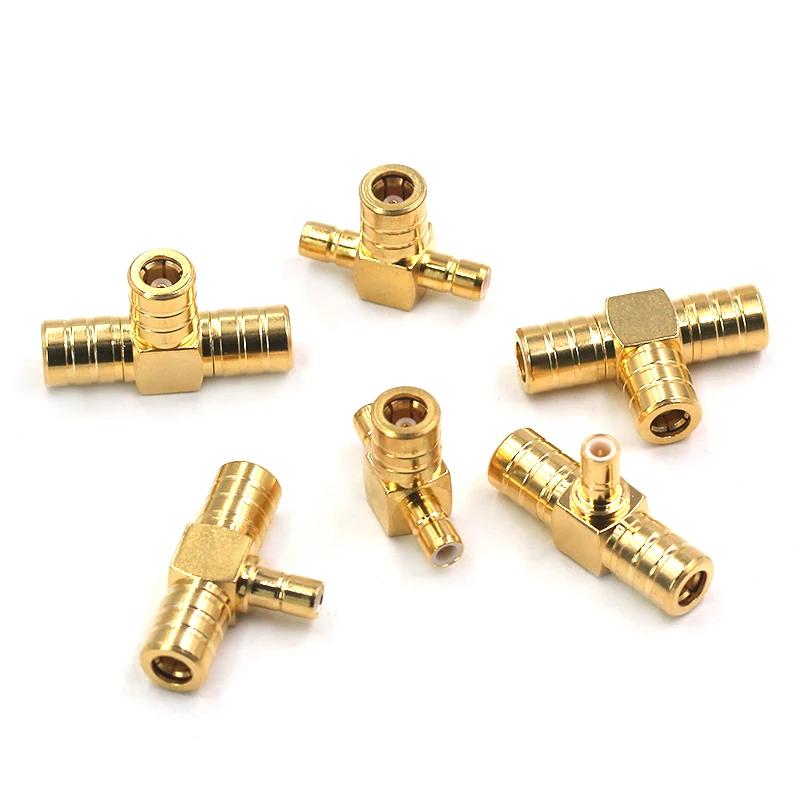
A selection of gold-plated SMB T-shaped RF adapters featuring different interface combinations for compact RF signal distribution.
Once the bulkhead fits the chassis, the next sourcing trap is the rear cable interface.
An SMB bulkhead crimp connector should be matched to the cable construction, not just to the words “RG174 compatible” in a marketplace title.
Choose crimp when batch consistency is the priority
Crimp termination is attractive for production because the process can be controlled through tooling.
But the correct result depends on the complete system:
- ferrule inside diameter;
- rear-body bore;
- cable jacket OD;
- braid diameter;
- dielectric diameter;
- center conductor size;
- strip dimensions;
- crimp die;
- operator process;
- pull-force acceptance.
If one of those changes, the crimp result can change.
For a repeat production assembly, document the cable manufacturer or at least the controlled cable dimensions. “RG174” alone may not provide enough purchasing control if the project is sensitive to dimensional variation.
Use solder only when the connector design actually calls for it
An SMB bulkhead solder connector may use a solder cup, solder center contact, or another cable-side solder structure.
Do not confuse that with a PCB solder connector.
The words “solder type” describe a termination process, not necessarily the mounting architecture.
For cable soldering, control heat exposure. Excessive heat can damage dielectric geometry, soften the cable jacket, or change the relationship between the center conductor and surrounding shield.
A visually acceptable joint is not automatically a good RF joint.
Do not assume one connector fits both RG174 and RG316
This is a practical sourcing problem.
RG174 and RG316 may appear similar enough that a buyer expects one small-coax connector to fit both. That should never be assumed.
Check:
- jacket OD;
- braid OD;
- dielectric OD;
- center conductor size;
- ferrule ID;
- cable entry bore;
- recommended strip length.
The front SMB interface may be identical while the rear termination is different.
For broader coax comparison work, the TEJTE RG Cable Guide should remain the cable-reference page. This bulkhead guide only needs enough cable detail to prevent the wrong rear termination from reaching production.
For production planning, the trade-off is practical:
| Production Factor | Crimp | Solder |
| Production speed | Higher | Lower |
| Tooling dependency | High | Moderate |
| Operator dependency | Lower with controlled tooling | Higher |
| Heat input | Low | Higher |
| Batch repeatability | Strong with controlled process | Process-dependent |
| Reworkability | Moderate | Often easier |
| Pull-force control | Tool/process controlled | Joint dependent |
| RG174 compatibility | Part-specific | Part-specific |
| RG316 compatibility | Part-specific | Part-specific |
The important entries are the last two. Neither termination style makes a connector universally compatible with a cable family.
How do you verify 50-ohm versus 75-ohm requirements?
Do not begin with the connector catalog.
Begin with the RF path.
The internal module, internal coax, bulkhead connector, external cable, and load should be reviewed as one impedance chain.
A simple audit looks like this:
| RF Path Item | Nominal Impedance | Evidence | Status |
| Internal RF module | Datasheet | ||
| Internal coax | Datasheet | ||
| SMB bulkhead | Drawing / specification | ||
| External coax | Datasheet | ||
| Antenna or load | Datasheet |
Treat 50-ohm SMB as a defined interface family
For a 50 ohm SMB bulkhead connector, the buyer should still confirm the exact part drawing, mounting geometry, cable interface, and frequency requirement.
The impedance label does not remove those mechanical checks.
It only answers one part of the RF path.
Require evidence for any 75-ohm SMB bulkhead part
A 75 ohm SMB bulkhead connector should be approved from manufacturer documentation rather than appearance.
Do not treat a connector as interchangeable with a 50-ohm version because:
- the outer shell looks similar;
- it snaps into the mating part;
- continuity passes;
- the sample appears normal at low-frequency inspection.
Request the actual interface definition, impedance specification, intended cable, and RF performance data.
A continuity test cannot answer this question.
The assembly can be electrically continuous and still be the wrong impedance, poorly terminated, or unsuitable for the intended operating band.
That distinction becomes more important once the connector is mounted into the chassis, because the next design decisions—grounding, anti-rotation, cable-backed architecture, and installed-state VNA testing—determine whether the mechanically correct assembly also behaves correctly as part of the finished RF system.
How should grounding and anti-rotation be handled at the chassis?
A bulkhead connector can be mechanically tight and still have a poor chassis interface.
That matters when the connector body is intended to become part of the RF shield or equipment ground. Paint, anodizing, loose hardware, and connector rotation can all change the final contact condition.
Decide whether the connector body is part of the chassis RF ground
Do not leave this as an assembly assumption.
The drawing or assembly specification should state whether the SMB bulkhead connector body must make conductive contact with the enclosure.
Check:
- bare conductive panel area;
- painted or anodized surfaces;
- conductive or non-conductive washers;
- EMI gasket;
- grounding washer;
- isolated mounting requirement;
- accepted bonding point.
If direct chassis contact is required, define where that contact must occur.
A production operator should not have to decide whether paint needs to be scraped away.
Keep the connector from rotating during service
Snap-on SMB mating is convenient, but the bulkhead body should not rotate every time the internal cable or external connector is serviced.
Possible anti-rotation controls include:
- a flat on the threaded body;
- D-shaped panel cutout;
- lock washer;
- secondary holding feature;
- defined installation torque;
- assembly fixture that holds the body during tightening.
Rotation can twist the rear coax, disturb a soldered joint, or introduce stress where the cable enters the ferrule.
The risk is easy to miss during first assembly because the connector may still pass continuity immediately after tightening.
For systems where chassis bonding matters, add a defined resistance or continuity check to the project inspection plan rather than relying only on visual inspection.
When does a cable-backed bulkhead make more sense than a direct feedthrough?
A direct feedthrough looks mechanically simple, but it works best when the internal RF path and panel port are already aligned.
Many compact enclosures are not.
The PCB may sit lower than the panel opening, move during final assembly, or require enough compliance to tolerate normal manufacturing variation.
Use a direct bulkhead where alignment is controlled
A direct structure can make sense when:
- internal and external RF paths line up;
- rear clearance is available;
- the board position is tightly controlled;
- cable movement is unnecessary;
- the connector can be installed without forcing the PCB into position.
The advantage is fewer flexible parts.
The disadvantage is that mechanical tolerance has less room to disappear.
Use a cable-backed connector when the PCB and panel cannot align naturally
A short coax section creates mechanical compliance:
PCB interface → coaxial cable → SMB bulkhead
This architecture can help with:
- offset PCB position;
- tight enclosures;
- assembly tolerance;
- vibration isolation;
- service loops;
- easier connector replacement.
The cable should not be treated as an unlimited mechanical correction, however. Tight bends immediately behind the connector can stress the termination and change installed RF behavior.
A practical decision path is:
- Are the internal and external RF paths naturally aligned? Yes: evaluate a direct feedthrough. No: evaluate a cable-backed bulkhead.
- Does the PCB move during assembly or service? Yes: cable compliance is usually safer.
- Will the external connector be mated frequently? Yes: make sure the chassis—not the PCB—carries that mechanical load.
- Is rear clearance limited? Yes: evaluate cable exit direction and bend radius before releasing the design.
How should the connector be tested after it is installed in the panel?
Bench testing a loose connector or cable assembly is useful, but the installed condition is what the equipment actually uses.
Mounting can introduce mechanical stress that was not present on the bench.
Start with visual and dimensional inspection
Before connecting a VNA, confirm the basics:
- correct connector part number;
- correct nut and washer sequence;
- full seating against the panel;
- adequate thread engagement;
- no connector rotation;
- correct center contact;
- correct rear termination;
- acceptable cable bend;
- no interference with nearby hardware.
A dimensional failure should not be sent to RF testing as though the only remaining question were insertion loss.
Separate mechanical acceptance from RF acceptance
Mechanical checks may include:
- panel fit;
- retention;
- anti-rotation;
- cable pull;
- panel deformation;
- hardware seating.
RF checks may include:
- continuity;
- S21;
- S11/S22;
- return loss;
- VSWR;
- repeatability after installation.
Continuity belongs near the beginning of the test sequence, not the end of the engineering argument. Passing continuity only shows that an electrical path exists.
Compare free-state and installed-state results
For a new design, test at least a few first articles before and after installation.
Useful comparisons include:
ΔS21 = S21 installed − S21 free and ΔRL = RLinstalled − RL free
The purpose is not to create one universal allowable delta. The acceptable change depends on the project frequency range and RF budget.
The comparison is useful because a large unexpected shift points the investigation toward installation.
Check for:
- cable bend stress;
- connector body distortion;
- rotation during tightening;
- poor chassis contact;
- stressed solder or crimp termination;
- altered cable routing.
Record the panel configuration with the result. A VNA screenshot without panel thickness, cable type, connector part number, and installation state is difficult to use when a later batch behaves differently.
Define incoming inspection before placing a production order
Incoming inspection should be written before the first production lot arrives.
Otherwise, the inspection plan tends to become whatever can be checked quickly after a problem appears.
Put obvious defects under full visual control
Depending on production volume and project risk, visible characteristics suitable for 100% checking can include:
- wrong interface;
- damaged center contact;
- thread damage;
- body deformation;
- missing nut or washer;
- incorrect rear termination;
- severe plating damage;
- contamination.
Critical dimensions that affect panel fit can then be sampled according to the approved quality plan.
Typical dimensions include:
- thread OD;
- usable thread length;
- shoulder diameter;
- anti-rotation geometry;
- ferrule dimensions;
- overall length.
For higher-risk assemblies, add RF and retention checks such as:
- insertion loss;
- return loss;
- cable pull;
- snap retention;
- chassis continuity;
- mating repeatability.
A useful lot-release concept is to keep one approved golden panel with the inspection fixtures.
If a new batch does not fit the golden panel as the approved sample did, stop release before hundreds of connectors reach assembly.
Build the RFQ around measurable panel requirements
“SMB female bulkhead connector” is not a complete RFQ.
The supplier still has to guess too much.
Define the interface before giving the mechanical dimensions
A production RFQ should state:
- SMB interface;
- center contact;
- nominal impedance;
- mounting direction;
- rear termination;
- cable type;
- frequency requirement.
Then add the mechanical stack:
- finished panel thickness;
- coating;
- washer;
- lock washer;
- gasket;
- usable thread requirement;
- anti-rotation feature;
- rear clearance.
Electrical acceptance requirements should also be measurable.
Instead of:
Good RF performance.
Use project-specific fields such as:
- operating frequency range;
- insertion-loss limit;
- return-loss or VSWR requirement;
- grounding requirement;
- inspection quantity;
- required test report.
A supplier-ready specification can follow this structure:
SMBInterface:
Center Contact:
Impedance:
Mounting Direction: Front / Rear
Rear Termination: Crimp / Solder / Other
Cable Type:Panel Hole:
Finished Panel Thickness:
Usable Thread Length:
Anti-Rotation Feature:
Washer / Nut Stack:
Grounding Requirement:Frequency Range:
Insertion-Loss Limit:
Return-Loss / VSWR Limit:
Retention Requirement:
Required Documentation:
Prototype Quantity:Production Quantity:
That form also makes substitution discussions easier. If a supplier offers another part, procurement has defined fields to compare instead of asking whether it is “the same SMB connector.”
Which design mistakes create panel rework later?
Several failures appear repeatedly because the connector, enclosure, and cable are released as separate purchasing decisions.
Cutting the chassis before approving the connector drawing
This is the expensive one.
Once hundreds of panels are machined or punched, a shoulder or anti-rotation change becomes a rework problem rather than a drawing correction.
Approve the connector drawing first.
Selecting the cable after the rear termination is fixed
A front interface does not define cable compatibility.
Late cable substitution can create:
- ferrule mismatch;
- poor braid capture;
- incorrect strip dimensions;
- excessive bend stress;
- weak pull retention.
Ignoring coating in the mounting-stack calculation
A small stack increase can remove the thread margin that existed on the bare prototype panel.
Evaluate the finished enclosure.
Letting external cable loads reach the internal PCB
If users repeatedly connect, disconnect, or pull an external cable, the chassis bulkhead should take that mechanical load.
Do not use the PCB or an internal cable termination as the unintended strain-relief structure.
Releasing production without a golden panel
Keep an approved panel or representative cutout fixture.
It becomes a fast reference for:
- incoming inspection;
- supplier validation;
- assembly training;
- first-piece approval;
- replacement-part evaluation.
FAQ
Should the panel hole be sized from the SMB thread diameter alone?
No. The thread is only one part of the mounting geometry. Check the shoulder, anti-rotation feature, washer, manufacturing tolerance, rear body, and required assembly access. The production cutout should be based on the approved connector drawing.
Can paint or powder coating make the bulkhead thread effectively too short?
Yes. Coating, washers, gaskets, and the panel itself consume usable threaded length. Calculate the complete finished mounting stack instead of checking bare sheet thickness alone.
Can the same SMB bulkhead connector terminate both RG174 and RG316?
Do not assume so. The RF mating interface may be identical while the rear cable geometry is different. Ferrule ID, cable entry bore, dielectric size, braid diameter, center conductor, and strip dimensions should match the specified coax.
Is an SMB female bulkhead connector automatically 50 ohms?
No. Gender and mounting style do not by themselves prove impedance. Use the approved manufacturer drawing and electrical specification, and verify that the rest of the RF path uses the intended impedance.
Does an SMB bulkhead connector always need direct electrical contact with the chassis?
No. It depends on the equipment grounding and shielding architecture. If the connector body is intended to be part of the RF chassis ground, define the conductive contact surface and inspection requirement. An isolated mounting design needs a different specification.
Can panel mounting change a connector’s VNA result?
Yes. Cable bending, connector rotation, body stress, grounding changes, and termination loading can all appear only after installation. For new designs, comparing free-state and installed-state measurements can expose these effects.
When is a cable-backed SMB bulkhead better than a direct feedthrough?
A short cable is useful when the PCB and chassis opening do not align, when internal parts move during assembly, or when vibration and service tolerance need to be isolated. The cable still needs adequate bend radius and strain control.
Release the connector, panel, and cable as one assembly decision
The safest SMB bulkhead design is not the one with the most detailed connector specification.
It is the one where the connector, enclosure, cable, installation sequence, and inspection method agree with each other.
Before production, confirm four things:
The interface mates correctly.The finished panel accepts the connector without forcing it.The rear termination matches the actual cable.The installed assembly meets the project’s mechanical and RF acceptance limits.
A connector that passes only the first check is not production-ready.
For a new SMB bulkhead connector project, send the supplier the mating interface, cable type, finished panel stack, panel drawing, operating frequency, RF acceptance requirement, and expected production quantity together. That information gives the supplier enough context to verify the complete assembly rather than quote a part that only looks correct in the catalog.
