
A cable assembly can pass continuity and still be the wrong RF part.
This happens more often than many buyers expect. The SMB connector snaps into place, the SMA interface matches the external equipment, and the first prototype works on the bench. The problem appears later: the cable is routed differently inside the enclosure, the bend radius becomes tighter, the production length changes, or the assembly is installed near a noisy power section.
For an RF engineer, an SMB to SMA cable is not simply a connector conversion cable. It is a controlled transition between a PCB-mounted RF port and an external RF interface. The cable choice, connector orientation, length, shielding structure, and termination quality all affect the final RF path.
In practical sourcing, the question is not only:
“Can SMB connect to SMA?”
The better question is:
“Can this SMB-to-SMA transition maintain the required RF behavior after it becomes part of the finished equipment?”
A typical signal path looks like:
RF board → SMB port → flexible coax cable → SMA interface → external cable / antenna / test equipment
Each section introduces mechanical and electrical requirements. The SMB side must protect the PCB connection. The coax must fit the available routing space. The SMA side must provide the correct external interface. The completed assembly must still meet impedance, insertion loss, VSWR, and mechanical requirements after installation.
This guide focuses on how engineers and buyers should specify, compare, and validate SMB-to-SMA cable assemblies for real applications.
Where should the flexible SMB-to-SMA link sit in the RF path?
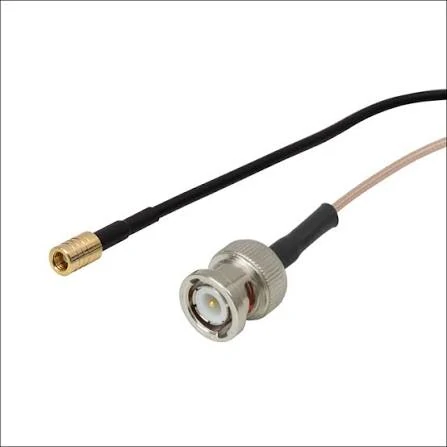
A coaxial cable assembly combining a BNC male interface with a miniature SMC female connector. This type of RF cable demonstrates the importance of identifying connector series, gender and locking method correctly.
The location of the cable inside the system determines what type of assembly is actually needed.
A common mistake during sourcing is treating an SMB to SMA cable as a simple adapter replacement. A rigid adapter may connect two interfaces, but it cannot always solve the mechanical problems that appear when a PCB port needs to reach a chassis-mounted connector.
A flexible cable assembly provides several functions at the same time:
- Interface conversion
- Mechanical routing
- PCB stress reduction
- Panel transition
- Service access
- Connector protection
For example, an RF module may have a small SMB jack located inside the enclosure, while the user needs an SMA female interface on the outside panel.
The complete structure becomes:
PCB SMB jack → SMB plug → coax cable → SMA female bulkhead → external antenna/test cable
In this case, the cable is part of the mechanical design, not just the electrical connection.
Map the path from the board connector to the external interface
Before selecting the cable, define the complete RF path.
A basic drawing should identify:
| Section | Question to Confirm |
| PCB interface | Is the board connector SMB jack or SMB plug? |
| Cable end | Does the assembly require SMB male or SMB female? |
| External interface | SMA male, SMA female, or SMA bulkhead? |
| Impedance | Is the system 50 Ω? |
| Frequency range | What is the highest operating frequency? |
| Cable route | Straight path or limited space bend? |
| Length | Fixed dimension or adjustable service loop? |
Many ordering mistakes come from describing only one side:
“Need SMB to SMA cable, 200 mm.”
This information is incomplete.
A supplier still needs to know:
- SMB gender
- SMA gender
- SMA mounting style
- cable type
- tolerance
- operating frequency
- RF acceptance requirements
A better specification would be:
SMB male right-angle to SMA female bulkhead cable, RG316, 50 Ω, 300 mm finished length, DC–6 GHz, VSWR requirement specified.
That description allows suppliers to build the same assembly.
Separate a pigtail from a rigid adapter
The term “SMB to SMA” can describe several different products.
They may look similar in a product search, but their application is different.
| Assembly Type | Structure | Typical Use |
| SMB to SMA cable | Flexible coax between connectors | PCB-to-panel transition |
| SMB to SMA pigtail | Short flexible cable with one or both fixed ends | Internal RF connection |
| SMB to SMA adapter cable | Cable assembly designed as an interface converter | Equipment integration |
| Rigid SMB to SMA adapter | Direct connector-to-connector body | Fixed alignment connection |
| SMA bulkhead cable assembly | Cable ending in panel-mounted SMA | External access port |
A rigid adapter works well when the two ports are already aligned.
A flexible cable is usually better when:
- the PCB position changes
- the enclosure has limited space
- vibration exists
- repeated maintenance is expected
- the external connector must be panel mounted
The wrong choice can create unnecessary mechanical loading on the SMB interface.
SMB connectors are compact snap-on interfaces. They are convenient for PCB connections, but they are not designed to absorb uncontrolled cable pulling or repeated side loading.
Match the architecture to the device
Different equipment designs require different SMB-to-SMA structures.
Common examples include:
| Application | Typical Assembly |
| RF module to enclosure connector | SMB plug to SMA bulkhead cable |
| Receiver PCB to external antenna | SMB to SMA antenna cable |
| Test board to front panel | SMB pigtail with SMA female panel mount |
| Internal radio module | Short RG316 SMB to SMA cable |
| Compact IoT equipment | Right-angle SMB to SMA assembly |
The same connector combination can behave differently depending on installation.
A 150 mm cable installed in free space is not the same as a 150 mm cable compressed inside a small enclosure.
The final routing condition affects:
- cable bend radius
- connector stress
- shielding effectiveness
- RF repeatability
Which end combination prevents the wrong cable from being ordered?
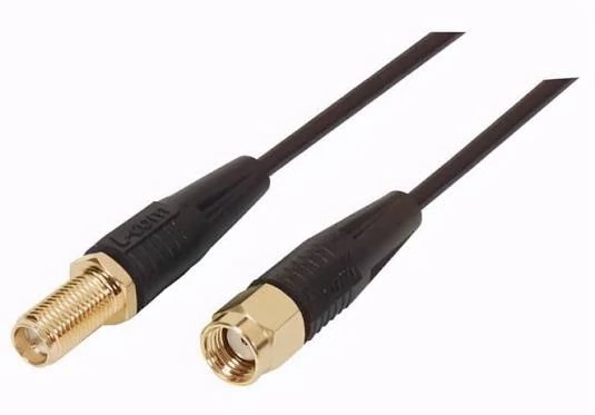
An SMA male to SMA female RF coaxial extension cable used to extend antenna or equipment connections. Cable length, impedance, attenuation and connector polarity should be confirmed before selection.
The connector names alone are not enough.
“SMB to SMA cable” describes two connector families, but not the complete mechanical interface.
A production-ready request should define both ends independently.
Decode the SMB end independently
The SMB side is usually connected to a PCB or internal RF module.
Confirm:
- Plug or jack
- Pin or socket
- Straight or right-angle
- Cable-mounted or board interface
- 50 Ω impedance
For example:
SMB male right-angle
is very different from:
SMB female straight
Even though both belong to the SMB family.
The wrong SMB gender may physically prevent mating, while the wrong orientation may create unnecessary stress during installation.
Decode the SMA end independently
The SMA side often connects to external equipment, antennas, or test instruments.
Confirm:
- SMA male or SMA female
- Bulkhead or free cable end
- Straight or right-angle
- Standard SMA or reverse polarity version
- Mounting thread requirements
A frequent sourcing issue is assuming all SMA connectors are interchangeable.
They are not.
A panel-mounted SMA female requires mechanical information such as:
- panel thickness
- thread length
- washer arrangement
- enclosure clearance
Without these details, a supplier may provide a connector that fits electrically but cannot be installed correctly.
Pay extra attention to SMB male to SMA female builds
The combination:
SMB male to SMA female cable
is commonly used in RF modules, GPS equipment, wireless devices, and test fixtures.
However, the assembly still requires confirmation of:
- SMB locking structure
- SMA mounting style
- cable diameter
- minimum bend radius
- finished length reference
A drawing should show the measurement method.
Information Asset: Cable End Identification Card
Before ordering an SMB-to-SMA cable assembly, buyers can use this simple identification sheet:
| Field | End A | End B |
| Connector family | SMB | SMA |
| Plug / jack | ||
| Center contact | Pin / Socket | Pin / Socket |
| Body direction | Straight / 90° | Straight / 90° |
| Mounting style | Cable / PCB | Cable / Bulkhead |
| Impedance | 50 Ω | 50 Ω |
| Mating device | ||
| Drawing reference |
This small document prevents many incorrect first samples.
A cable assembly can be electrically correct but mechanically unusable. Defining both connector ends before quotation helps suppliers quote the same product and helps buyers compare offers fairly.
How do you choose RG178, or RG316 for the route?
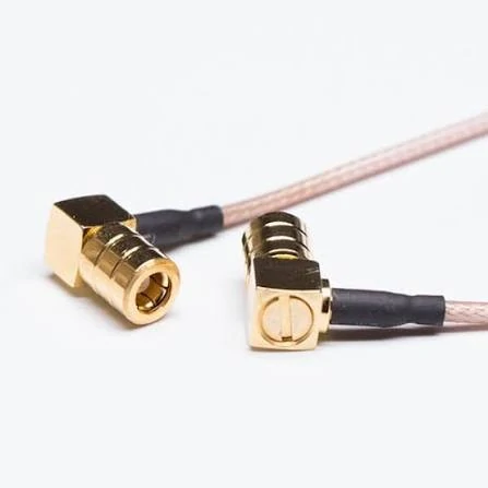
Right-angle miniature RF connectors allow the coaxial cable to exit sideways, helping reduce bend stress and enclosure interference in compact electronic equipment.
The connector interface usually receives the most attention during RF cable selection. The cable itself is often treated as a secondary detail.
That is a mistake.
In an SMB-to-SMA assembly, the coaxial cable determines several practical limits:
- How tightly the assembly can be routed
- How much insertion loss is added
- How much mechanical stress reaches the connectors
- How stable the RF performance remains after installation
- Whether the assembly survives repeated movement
A cable that looks suitable in a quotation may become the limiting factor after the product enters production.
For example, a short RG174 assembly may work perfectly in a prototype. After enclosure redesign, the same cable may need a tighter bend, a longer path, or higher temperature exposure. The original selection may no longer match the application.
The cable should be selected based on the complete assembly requirement, not only the connector combination.
Use RG178 when diameter and temperature both matter
RG178 is often chosen when the assembly needs a smaller cable envelope.
Typical conditions:
- Limited internal space
- Compact RF modules
- Tight cable exits
- Higher temperature requirements
Compared with many general-purpose flexible coax cables, RG178 offers:
- Very small outer diameter
- PTFE dielectric structure
- Good temperature capability
The limitation is that small diameter does not automatically mean better RF performance.
The reduced size can increase attenuation, especially as frequency increases.
For miniature assemblies, RG178 may solve a mechanical problem that a larger cable cannot.
The decision should be based on:
- available routing space
- operating frequency
- allowable insertion loss
- required flexibility
Choose RG316 when mechanical margin and temperature capability matter
RG316 is one of the most common choices for compact RF cable assemblies.
A typical RG316 SMB to SMA cable is used in:
- RF modules
- industrial electronics
- test equipment
- communication devices
- compact antenna systems
Reasons engineers choose RG316 include:
- PTFE dielectric
- stable temperature capability
- flexible construction
- good mechanical durability
- compatibility with many miniature RF connectors
However, RG316 is not automatically the correct choice for every application.
A short low-cost internal jumper may not need its additional margin.
A high-frequency test cable may require a different cable family.
The correct question is:
Does the complete SMB-to-SMA assembly need the mechanical and environmental advantages of RG316?
Compare cable families by assembly-level criteria
The following table is intended for initial selection, not a replacement for manufacturer datasheets.
| Criteria | RG174 | RG178 | RG316 |
| Cable diameter | Small | Very small | Small |
| Flexibility | High | High | High |
| Space requirement | Good | Excellent | Good |
| Temperature capability | General | Higher | Higher |
| Typical use | Cost-sensitive internal links | Miniature assemblies | Industrial RF assemblies |
| SMB/SMA compatibility | Common | Application dependent | Very common |
| Long cable routing | Limited by loss | Limited by loss | Better margin |
The cable family should be selected together with:
- connector body size
- termination method
- bend requirement
- frequency range
- environmental conditions
A connector designed for RG316 should not automatically be used with RG174. The rear body, ferrule size, center pin position, and termination process may be different.
The front interface may look identical, but the completed assembly can fail during production.
How long can the jumper be before loss consumes the RF budget?
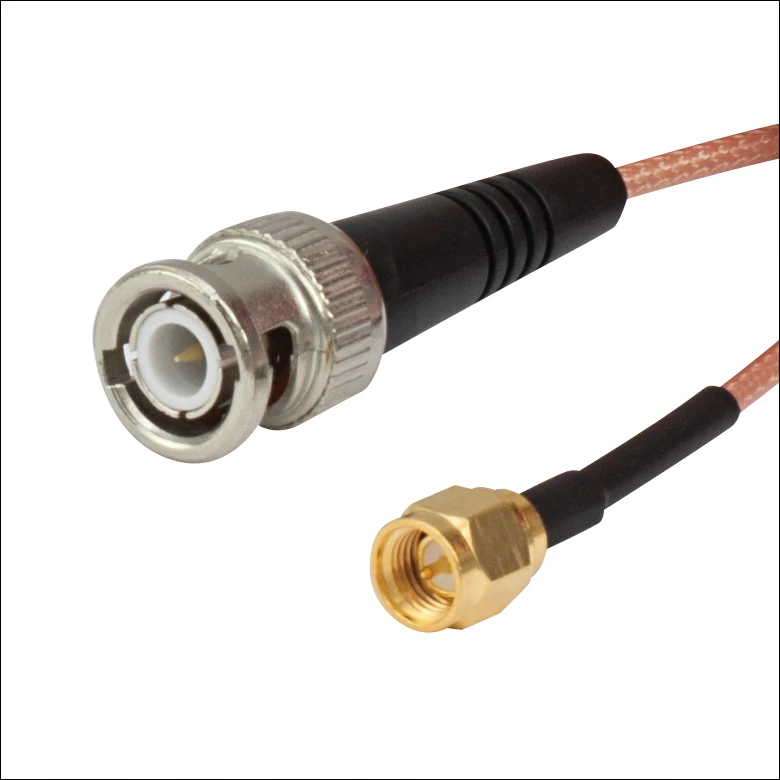
A BNC male to SMA male coaxial cable assembly designed for connecting RF equipment with different connector interfaces. The flexible RG316-style cable supports compact routing and RF system integration.
A common RF purchasing mistake is asking:
“What is the maximum length?”
There is no universal answer.
The maximum usable length depends on:
- operating frequency
- cable attenuation
- connector losses
- allowed system loss
- required RF margin
A 300 mm cable at 900 MHz and a 300 mm cable at 6 GHz are not equivalent.
The frequency changes the loss.
Start with cable loss at the actual operating frequency
The basic cable loss calculation is:
ILcable(f)=α(f)×L
Where:
- α(f) = cable attenuation at the operating frequency
- L = cable length
Example:
If a cable has:
- attenuation = 1 dB/m at the working frequency
- length = 0.5 m
The cable contribution is:
1×0.5=0.5dB
This calculation does not include connector transitions.
Add both connector transitions into the loss budget
A finished SMB-to-SMA cable assembly contains more than coax.
The total insertion loss can be considered as:
ILtotal(f)=α(f)L+ILSMB+ILSMA+M
Where:
- ILSMB = SMB termination contribution
- ILSMA = SMA termination contribution
- M = design margin
This margin is important.
A production assembly may have variation caused by:
- cable preparation
- crimp quality
- solder process
- connector tolerance
- measurement repeatability
A design using only the theoretical minimum loss leaves little room for production variation.
Convert allowed loss into maximum cable length
For a known system loss limit:
Lmax=α(f)ILbudget−ILSMB−ILSMA−M
This formula is useful during RF quotation discussions.
Instead of asking:
“Can you make this cable 1 meter?”
The buyer can define:
“The assembly must maintain insertion loss below X dB from X MHz to X GHz.”
That gives suppliers a measurable target.
Example: loss budget comparison
| Application | Cable Requirement | Main Risk |
| 915 MHz sensor module | Short RG174/RG316 link | Mechanical fit |
| 2.4 GHz wireless device | RG316 or RG174 depending on length | Insertion loss |
| 5–6 GHz RF module | Lower-loss cable selection | Frequency margin |
The same SMB-to-SMA interface may require different cable decisions depending on the frequency band.
Reject vague RF requirements such as “low loss”
“Low loss” is not a specification.
A supplier cannot verify it without:
- frequency range
- cable length
- acceptable dB limit
- measurement method
A better RF requirement:
SMB male to SMA female RG316 cable assembly, 500 mm, 50 Ω, DC–6 GHz, insertion loss ≤ X dB, VSWR ≤ X.
This information creates a measurable acceptance standard.
When should the SMA end become a bulkhead interface?
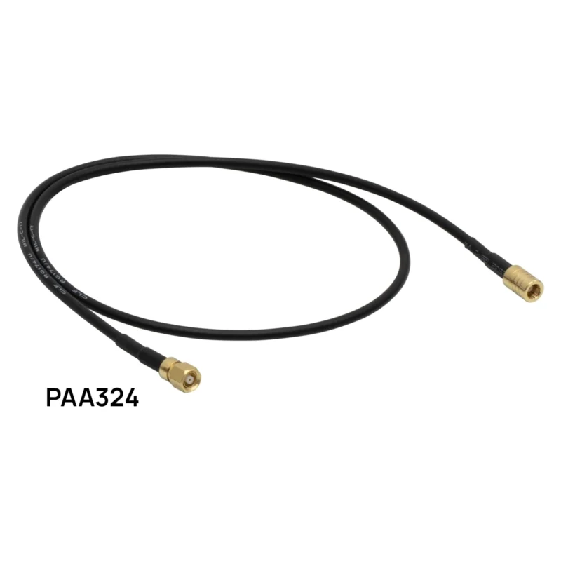
The SMA side of an SMB-to-SMA cable often becomes the mechanical connection point between the internal RF circuit and the outside environment.
This is where many assembly problems appear.
A free SMA connector hanging inside an enclosure may work during testing but create problems during customer installation.
Move repeated mating away from the PCB
A common structure is:
PCBSMB → coax cable → SMA female bulkhead → external cable
The benefit is simple:
The user connects to the panel SMA.
The internal SMB connection stays protected.
This reduces:
- PCB connector wear
- accidental pulling force
- maintenance damage
- cable movement near sensitive RF components
For products with external antennas, this structure is often easier to service.
Define the complete panel stack
A bulkhead SMA assembly requires more than the connector name.
The mechanical stack may include:
- SMA bulkhead body
- panel thickness
- thread length
- nut
- washer
- lock washer
- gasket or O-ring when required
A common mistake is specifying only:
SMA female bulkhead
without defining the enclosure.
The connector may fit electrically but fail mechanically.
Measure cable length from fixed reference points
Cable length should always use a repeatable measurement method.
Examples:
- SMB mating plane → SMA shoulder
- SMB mating plane → SMA mating plane
- PCB reference point → panel reference point
Avoid unclear descriptions such as:
200 mm cable
because suppliers may measure from different locations.
For production orders, the drawing should define:
- finished length
- tolerance
- reference point
- cable exit direction
Check the enclosure before freezing the SMA design
Before finalizing the assembly, confirm:
- panel thickness
- paint thickness
- gasket compression
- washer stack
- nut engagement
- internal clearance
- cable bend space
A bulkhead connector is a mechanical interface first and an RF interface second.
Both need to be considered together.
Should the SMB end exit straight or at 90 degrees?
The connector angle is often decided by available space, but it also affects mechanical stress.
A straight SMB connector and a right-angle SMB connector may use the same interface standard. However, they create different cable paths after installation.
Selecting the wrong orientation can cause:
- excessive bending near the connector
- contact stress on the PCB port
- enclosure interference
- inconsistent production assembly
The correct choice depends on the physical relationship between the PCB port and the cable routing path.
Use a straight SMB end when axial space is available
A straight SMB connector is usually suitable when:
- the PCB port faces the cable route
- there is enough vertical clearance
- the cable can leave the connector without immediate bending
- the assembly requires simple routing
Typical examples:
- open-frame RF modules
- test fixtures
- larger enclosures
- low-density PCB layouts
The advantage is simplicity.
A straight connector normally provides:
- easier assembly
- easier inspection
- fewer orientation variables
- simpler drawings
However, the cable should not be bent immediately after the connector.
Every coaxial cable has a minimum bend radius. Forcing the cable directly after the connector can affect:
- center conductor alignment
- dielectric deformation
- shielding structure
- long-term reliability
Turn 90 degrees when the straight connector creates mechanical stress
A right-angle SMB is often selected when the PCB space is limited.
Typical situations:
- low-profile enclosure
- connector close to the PCB edge
- nearby components blocking vertical clearance
- cable needs to follow the board direction
A right-angle SMB to SMA cable can reduce unnecessary cable bending.
However, a 90-degree connector is not automatically better.
A wrong orientation may create another problem:
- cable exits toward a component
- SMA side cannot reach the panel
- assembly direction changes between production batches
The drawing should define:
- connector orientation
- cable exit direction
- rotation angle
- reference view
Check the installed direction after mating
A common prototype issue:
The cable works when connected outside the enclosure.
After installation:
- the cable twists
- the SMA bulkhead does not align
- the lid compresses the cable
- the SMB connector receives side force
The assembly drawing should show the final installed position.
Important dimensions include:
| Item | Reason |
| Cable exit direction | Prevent rotation differences |
| Minimum bend radius | Protect RF stability |
| First clamp position | Reduce connector load |
| Clearance zone | Avoid enclosure interference |
| Connector orientation | Ensure repeatable assembly |
How do you keep cable motion away from the SMB snap interface?
SMB connectors are popular because they are compact and quick to mate.
That same snap-on structure creates a design consideration.
A cable assembly should not rely on the SMB connector alone to support cable weight or movement.
The connector is an electrical interface.
It is not a mechanical mounting point for uncontrolled cable forces.
Create a no-bend zone behind the connector
A frequent production failure occurs when the cable is bent immediately after termination.
The assembly drawing should define:
- straight section behind connector
- first bending point
- minimum bend radius
- heat-shrink position
- boot length
This is especially important for small coax cables.
A cable that passes electrical testing during inspection may still fail later because repeated movement changes the internal geometry.
Add strain relief before adding more cable length
Some designers add extra cable length to create a service loop.
A service loop can help installation, but it does not automatically protect the connector.
Too much free cable can create:
- unnecessary movement
- vibration stress
- pulling force on SMB
- inconsistent RF results after installation
Better solutions include:
- cable clamp
- adhesive mounting point
- mechanical bracket
- heat-shrink boot
- molded strain relief
The objective is controlling cable movement.
Prevent removal by pulling the coax
A typical field mistake:
The user removes the cable by pulling the coax instead of holding the connector body.
This can gradually damage:
- SMB retention force
- connector interface
- cable termination
- PCB solder connection
For production equipment, installation instructions and mechanical support should consider this possibility.
Installed cable-load checklist
Before releasing a design, verify:
| Check Item | Acceptance Question |
| SMB support | Is cable weight supported near the connector? |
| PCB stress | Does installation bend the board? |
| Rotation | Does the connector rotate during use? |
| Bend radius | Is minimum radius maintained? |
| Enclosure | Does the cover compress the cable? |
| RF stability | Does movement change measured RF response? |
This type of mechanical verification is often skipped because continuity testing passes.
How should shielding be evaluated in a noisy enclosure?
A cable may have a “double shield” description, but that alone does not define real shielding performance.
For SMB-to-SMA assemblies used near:
- DC/DC converters
- digital processors
- motor wiring
- switching power circuits
the installed environment matters.
The important factors include:
- shield coverage
- termination quality
- connector body continuity
- transfer impedance
- screening attenuation
- cable routing
Do not use shield count as the only acceptance requirement
A two-layer braid does not automatically outperform every single-shield cable.
The complete assembly determines performance.
Weak points often appear at:
- connector transition
- poor braid termination
- damaged cable during bending
- inconsistent assembly process
The cable and connector must work together.
Compare shielding under the real routing condition
A cable tested on a bench may behave differently after installation.
Consider:
| Installation Condition | Potential Concern |
| Near switching power supply | Noise coupling |
| Parallel with digital lines | Signal interference |
| Near motor harness | EMI environment |
| Inside metal enclosure | Grounding method |
For standard short RF jumpers, basic RF testing may be enough.
For sensitive receiver systems, EMC-related requirements should be defined during sourcing.
Build one drawing that every supplier interprets the same way
A supplier can only manufacture what the drawing defines.
Many cable sourcing problems are caused by incomplete documentation.
A product name is not a manufacturing specification.
Put both connector identities directly on the drawing
Avoid:
SMB to SMA cable
Instead specify:
SMB male right-angle → SMA female bulkhead
Include:
- connector gender
- orientation
- mounting style
- cable type
Dimension the finished assembly from repeatable references
The drawing should define:
- finished length
- length tolerance
- measurement reference
- cable exit direction
- bend area
- label position
For bulkhead assemblies, also include:
- thread length
- panel thickness
- hardware stack
Define RF requirements beside mechanical dimensions
A supplier needs both mechanical and electrical requirements.
Recommended fields:
| Requirement | Specification |
| Connector interface | SMB / SMA type |
| Impedance | 50 Ω |
| Cable family | RG174 / RG178 / RG316 |
| Frequency range | Required band |
| Insertion loss | Maximum limit |
| VSWR / return loss | Acceptance value |
| Temperature | Operating range |
| Shielding | Requirement if needed |
| Test report | Required or not |
A cable without RF limits is only a mechanical drawing.
How should first articles be tested in their final routed shape?
A first article should not only be checked as a loose cable.
The final installation condition matters.
A cable can pass continuity and still fail RF requirements.
Inspect workmanship before VNA testing
Visual inspection should include:
- wrong connector combination
- damaged SMA thread
- incorrect SMB termination
- exposed braid
- jacket damage
- heat-shrink position
- missing bulkhead hardware
These defects are usually easier to detect before RF testing.
Perform continuity while moving the cable
Static continuity testing is not enough.
During inspection, check:
- center conductor continuity
- shield continuity
- insulation resistance
- intermittent connection during movement
A cable assembly may pass a static test but fail after bending.
Sweep the full application band
For RF validation, measure:
- S21 insertion loss
- S11 return loss
- S22 return loss
Record:
- test frequency
- calibration plane
- cable routing condition
- fixture information
The installed condition should be included.
Compare free-state and installed-state results
A useful engineering comparison is:
ΔS21=S21installed−S21freeΔRL=RLinstalled−RLfree
Test conditions can include:
- Cable straight
- Normal service loop
- Minimum approved bend
- Installed inside enclosure
This identifies whether the design itself creates RF instability.
Release production lots with measurable acceptance rules
A production cable assembly needs repeatable acceptance criteria.
Inspection should separate:
- obvious manufacturing defects
- RF performance verification
Put visible defects under 100% inspection
Recommended checks:
| Item | Method |
| Connector identity | Visual |
| Cable type | Label / drawing |
| Finished length | Measurement |
| SMA thread | Gauge / visual |
| SMB mating condition | Visual |
| Jacket condition | Visual |
| Part number | Record |
Use risk-based sampling for RF characteristics
Not every assembly needs the same testing level.
Typical sampling items:
- insertion loss
- return loss
- retention force
- pull test
- bend response
- dimensions
Increase inspection after:
- cable supplier change
- connector supplier change
- crimp tool replacement
- drawing revision
- previous lot failure
Which cases justify a custom cable instead of a stock pigtail?
A stock SMB-to-SMA pigtail is suitable when the application is simple.
Examples:
- standard connector combination
- common RG316 cable
- standard length
- indoor use
- relaxed tolerance
Custom cable becomes valuable when the system has mechanical restrictions.
Move to custom when the enclosure controls the design
Typical triggers:
- non-standard length
- SMA bulkhead requirement
- right-angle SMB orientation
- fixed cable exit direction
- controlled bend position
- special shielding
- temperature requirement
- serialized inspection report
The higher cost of customization may be lower than the cost of:
- assembly rework
- panel redesign
- connector damage
- field replacement
Custom Cable Trigger Score
Score one point for each condition:
| Condition | Score |
| Special connector orientation | 1 |
| Bulkhead required | 1 |
| Custom thread length | 1 |
| Tight length tolerance | 1 |
| Defined RF loss limit | 1 |
| High temperature | 1 |
| Vibration environment | 1 |
| Special shielding | 1 |
| Individual RF report | 1 |
Recommendation:
- 0–2 points: Standard cable may be enough
- 3–5 points: Modified standard assembly
- 6–9 points: Custom drawing-controlled assembly recommended
FAQ
How long can an SMB to SMA cable be before a larger coax is needed?
There is no fixed maximum length. The limit depends on frequency, cable attenuation, connector loss, and system loss budget. A short RG316 pigtail may work well at higher frequencies, while a longer assembly may require a lower-loss cable.
Should the SMA side be bulkhead mounted or left as a free cable end?
A bulkhead SMA is usually preferred when the external connector will be accessed repeatedly. It transfers mechanical load to the enclosure instead of the internal SMB connection.
Does a right-angle SMB always reduce PCB stress?
No. A right-angle connector can improve routing, but incorrect orientation or insufficient strain relief can still create side loading on the PCB connector.
Should shielding performance be tested for SMB-to-SMA cables above 3 GHz?
For EMC-sensitive systems, additional shielding evaluation may be useful. The requirement should define the measurement method instead of only requesting “double shield.”
When is a custom finished length worth specifying?
Custom length is valuable when cable routing, connector stress, bulkhead position, or RF loss limits affect the final equipment design. A controlled drawing is usually better than selecting the nearest stock size.
Final Buying Guidance
An SMB-to-SMA cable assembly should be specified as a complete RF component, not as two connector names joined together.
Before placing an order, define:
- SMB interface
- SMA interface
- connector orientation
- cable type
- impedance
- operating frequency
- finished length
- bend requirement
- installation environment
- RF acceptance limits
The most expensive cable is often not the custom one. It is the cable that reaches production and requires redesign.
If the assembly will operate near the upper frequency range, provide the operating frequency, cable length, connector count, and inspection requirements before quotation. This allows the supplier to evaluate whether a standard SMB-to-SMA assembly is sufficient or whether a controlled custom design is more appropriate.
