
The adapter threads onto both ports. Continuity passes. The installation still fails.
This happens when an N to TNC adapter is selected only by connector names. The buyer confirms that one side is N-Type and the other is TNC, then releases the order without checking impedance, operating frequency, cable weight, environmental sealing, or the exact male and female interfaces.
The error may stay hidden during a short bench test. It becomes obvious after a heavy feeder is installed, the equipment is moved, or the RF path is swept near its upper operating band.
An adapter is a small part, but it sits directly in the signal path. Its job is not merely to make two threads fit. It must preserve the intended impedance, survive the mechanical load, and provide measurable RF performance across the required frequency range.
Where Does the N-to-TNC Transition Sit in the RF Path?

Start with the equipment, not the adapter catalog.
A common installation looks like this:
Industrial Radio→ TNC Equipment Port→ N-to-TNC Adapter→ N-Type Feeder Cable→ Outdoor Antenna A test setup may run in the opposite physical order:
N-Type Analyzer Port→ N-to-TNC Adapter→ TNC Test Cable→ Device Under Test The signal direction can change, but the mechanical mating ends do not. Record the connector already installed on each device and identify which mating interface must be provided by the adapter.
This first step also reveals whether a rigid adapter is sensible. A short transition between aligned bench instruments may be straightforward. A permanent transition between a small TNC equipment port and a thick outdoor feeder deserves more attention.
The broader TNC connector guide explains TNC gender, cable compatibility, threaded coupling, and common equipment applications. For an N-to-TNC transition, those details must be considered together with the larger N-Type side. TEJTE’s TNC guide also notes that connector appearance alone does not determine suitability; cable construction, installation conditions, and manufacturing tolerances affect the finished RF path.
Before selecting a part, complete a basic path record:
Source equipment: Source connector: Destination equipment: Destination connector: Cable family: Nominal impedance: Operating band: Indoor or outdoor: Permanent or temporary installation: Number of existing adapters:
A direct N-to-TNC adapter is usually preferable to a stack such as:
N-Type→ N-to-SMA Adapter→ SMA Coupler→ SMA-to-TNC Adapter Every additional interface adds another contact pair, another possible mismatch, and another place for moisture or mechanical loosening.
How Can You Identify the Exact Mating Ends?
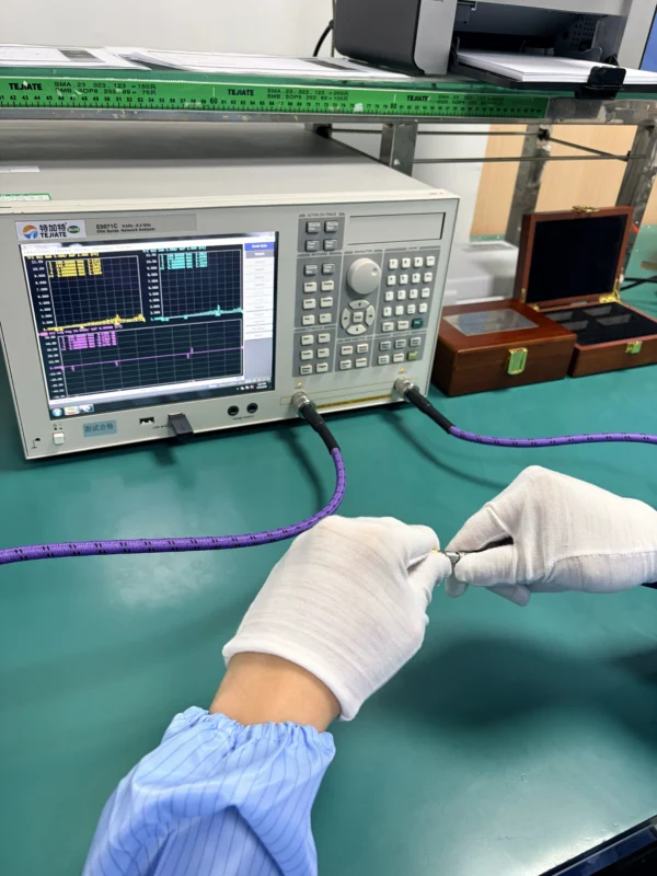
“N to TNC” is not a complete mechanical description.
Both interfaces must be identified independently. Inspect the center contact and the coupling structure rather than relying only on the equipment label.
For a standard-polarity interface:
- A male connector normally has a center pin.
- A female connector normally has a center socket.
- The mating adapter must provide the opposite gender.
- Thread location should be checked alongside the center contact.
TNC uses threaded coupling. TEJTE’s TNC guide describes the male side as having a center pin and coupling nut, while the female side has a center socket and the corresponding external mating thread.
N-Type also uses threaded coupling, but N-Type products exist in both 50-ohm and 75-ohm versions. That makes visual identification alone insufficient for the electrical specification. TEJTE’s N-Type connector guide distinguishes those impedance systems and discusses N-Type use with outdoor antennas and larger low-loss feeder cables.
N-to-TNC gender translation table
| Existing N-Type port | Existing TNC port | Adapter required |
| N female | TNC female | N male to TNC male |
| N female | TNC male | N male to TNC female |
| N male | TNC female | N female to TNC male |
| N male | TNC male | N female to TNC female |
| Not confirmed | Not confirmed | Request photos and interface drawings |
A request for an N female to TNC male adapter means the adapter itself has an N-Type female interface and a TNC male interface. It does not describe the genders on the two pieces of equipment.
That wording causes many purchase errors. One engineer describes the equipment ports. Another person writes the adapter genders. Both may use the same phrase while expecting different products.
The purchase file should contain an annotated drawing or clear close-up photographs showing:
- N-Type side
- TNC side
- Center pin or socket
- Internal or external coupling thread
- Mating reference plane
- Overall length
- Straight or right-angle orientation
Do not approve a quotation based only on a product title.
Does Reversing the Search Phrase Change the Part?
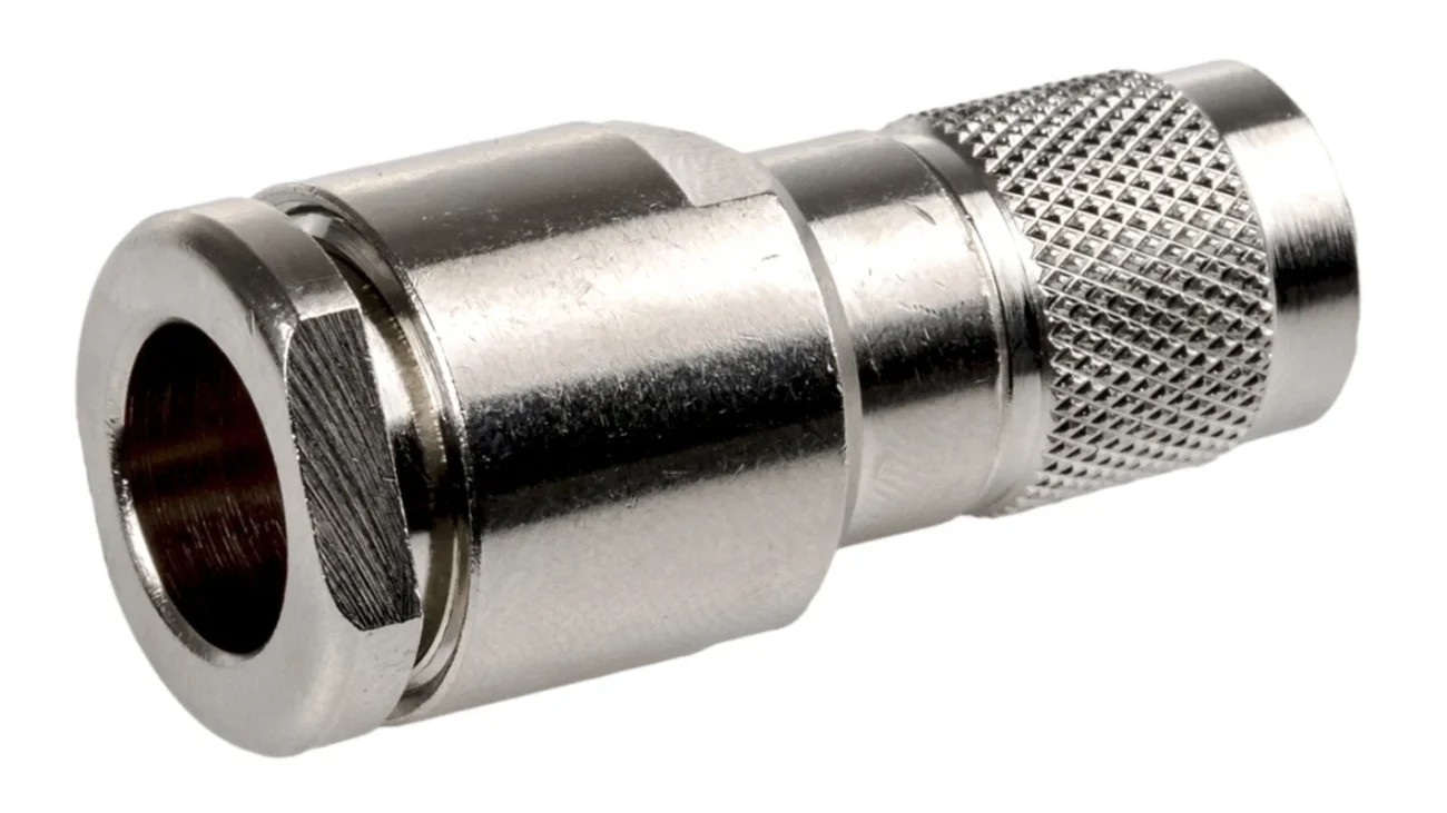
Usually, no.The phrases N to TNCadapter, TNC to N adapter, N-Type to TNC adapter, and TNC to N-Type adapter often describe the same product family. The word order normally reflects the point where the buyer begins describing the connection.
A passive straight-through adapter is generally bidirectional. It can be used in a receive path or a transmit path. The physical product is determined by:
- Interface family on each side
- Male or female gender
- Standard or reverse polarity
- Nominal impedance
- Straight or right-angle construction
- Verified frequency range
- Environmental configuration
For example, these two descriptions normally identify the same mating-end combination:
N male to TNC female adapter TNC female to N male adapter
Before quotation, normalize the description:
N-Type Male to TNC Female Adapter 50 Ohm Straight Operating Frequency: DC to 6 GHz
Avoid descriptions such as:
N/TNC connector N to TNC piece TNC adapter for antenna
They do not define a purchasable RF component.
Which Component Sets the Frequency Ceiling?
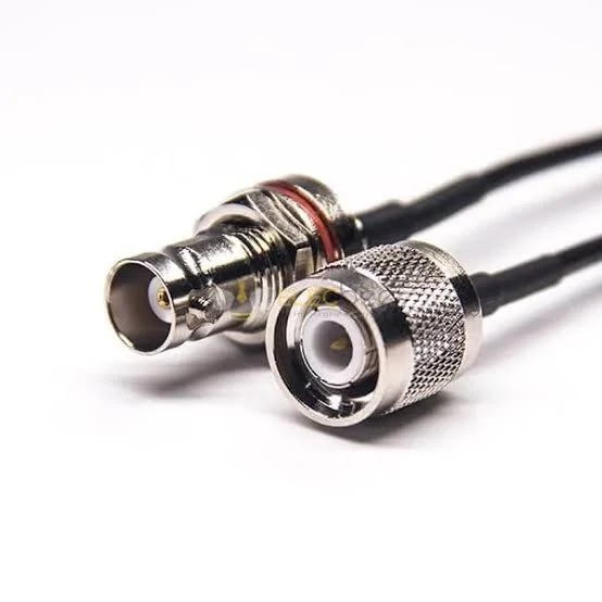
Close-up image of RF coaxial cable connectors illustrating different coupling structures. Buyers should verify the connector family, center pin or socket, thread type, and required mating gender before ordering an N-to-TNC adapter.
The connector family’s highest published capability is not automatically the rating of the selected adapter.
Use the lowest verified maximum frequency in the assembled path:
Suppose the equipment ports are rated to 11 GHz, the adapter is verified to 6 GHz, and the cable assembly is approved only to 3 GHz. The usable path does not become an 11 GHz system. Its verified ceiling remains 3 GHz.
Amphenol RF publishes standard TNC series data at 50 ohms with operation to 11 GHz, while some extended-range designs reach 18 GHz. The same series page lists different maximum insertion-loss values for straight and right-angle M39012 configurations, which is a useful reminder that geometry matters.
A specific commercial between-series example, Amphenol part 000-78875, is listed as an N-Type plug to TNC plug adapter with 50-ohm impedance, straight orientation, PTFE insulation, and a maximum frequency of 11 GHz. Those values apply to that part, not to every adapter that looks similar.
This distinction matters during supplier substitution. Two products can share:
- The same connector genders
- Similar body length
- Nickel-plated brass bodies
- A 50-ohm description
Their upper-frequency behavior may still differ because of internal conductor diameter, dielectric support, right-angle geometry, contact alignment, and manufacturing tolerance.
Specify the actual operating band. “Up to 11 GHz” is less useful than:
Primary operating band: 2.3 to 2.7 GHz Acceptance sweep: 10 MHz to 3 GHz Required test points: 700 MHz, 2.4 GHz, 2.6 GHz
The latter tells the supplier how the component will be evaluated.
How Much Reflection Can the Adapter Add?
An adapter can pass continuity and still produce poor return loss.
Continuity confirms that the center conductors and outer conductors are electrically connected. It does not confirm that the adapter maintains a controlled 50-ohm transition across the operating band.
Check every item in the path:
- N-Type equipment port impedance
- TNC equipment port impedance
- Adapter impedance
- Cable impedance
- Antenna, load, or instrument impedance
This deserves explicit attention because N-Type interfaces can be supplied in 50-ohm or 75-ohm versions, while mainstream TNC RF products are commonly specified as 50 ohms.
Cable attenuation and adapter mismatch are also different problems.
Cable attenuation normally increases with frequency and length. Adapter insertion loss is the transmitted power lost through the transition. Return loss or VSWR indicates how much of the signal is reflected by impedance discontinuity.
Where a purchase specification gives VSWR but the supplier reports return loss, use:
A maximum VSWR of 1.30:1 corresponds to roughly 17.7 dB minimum return loss. Small rounding differences are normal, but the test frequency and reference plane must be the same.
A practical RF budget should separate:
Cable attenuation: Adapter insertion loss: Connector mismatch: Additional coupler loss: Remating variation: Remaining system margin:
Do not assign the entire measured loss to the adapter before accounting for the cables and test fixtures.
A VNA measurement is especially sensitive to reference-plane placement. Calibrating at the instrument ports and then adding uncharacterized test cables can make the adapter appear worse—or better—than it is.
When Does a Rigid Body Become a Mechanical Liability?
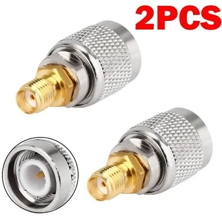
Two threaded RF coaxial adapters used to demonstrate connector-interface identification. External appearance alone cannot confirm whether an adapter is N-to-TNC, N-to-SMA, or another between-series configuration.
The N-Type side is often connected to a heavier cable than the TNC side.
That mismatch creates a mechanical problem. A rigid adapter can transfer the cable’s weight and side load directly into a smaller equipment port, thin panel, or PCB-mounted connector.
A simplified bending-moment check is:
M=F×dM=F\times dM=F×d
Where:
- MMM is the bending moment at the equipment port.
- FFF is the cable weight or applied side force.
- ddd is the distance from the panel to the load point.
The formula is simple, but it explains why a short adapter with supported cable may survive while a long adapter stack with unsupported LMR-400 damages the same port.
High-risk conditions include:
- Heavy low-loss feeder cable
- Horizontal cable without a clamp
- Long rigid adapter body
- Vehicle or machinery vibration
- Portable test equipment
- Frequent relocation
- Recessed or thin equipment panels
- PCB-supported TNC connectors
- Side pull during installation
A continuity test performed with the cable lying flat on a bench will not reproduce those loads.
TEJTE port-stress screening score
The following score is a practical screening tool, not an industry standard.
Rate each item from 1 to 5:
Port Stress Score =Adapter Length+ Cable Weight+ Cable Stiffness+ Side Pull+ Vibration Exposure+ Panel Weakness Interpret the result as follows:
- 6–10: A rigid adapter may be acceptable.
- 11–18: Add cable support and validate the installation.
- 19–30: Replace the rigid transition with a flexible jumper or bulkhead solution.
Even a low score does not replace mechanical qualification. It simply identifies projects that require more attention before sample approval.
Should You Specify Straight, Right-Angle, or a Jumper?
A straight adapter is the shortest transition, but it is not always the lowest-risk installation.
Use a straight adapter when:
- The two connection axes align
- There is enough axial clearance
- The attached cable is light or supported
- The transition is temporary
- Nearby ports do not interfere
- The shortest practical signal path is preferred
A right-angle N to TNC adapter helps where the cable cannot exit directly behind the equipment. It may solve enclosure-clearance problems, but the elbow orientation must be checked after mating. The final position depends on which side rotates during installation and how the coupling nuts seat.
Do not assume that a right-angle model can replace a straight adapter without qualification. Right-angle geometry can have different RF limits, body dimensions, torque behavior, and environmental joints.
A flexible jumper is normally safer when routing and strain isolation matter more than minimum path length. It gives installers room to:
- Offset misaligned ports
- Support a heavy feeder independently
- Isolate vibration
- Reach recessed equipment ports
- Route around enclosure walls
- Replace the transition without loading the device connector
Structure selection matrix
| Installation requirement | Straight adapter | Right-angle adapter | Flexible jumper |
| Ports aligned | Preferred | Optional | Suitable |
| Limited rear clearance | Poor | Preferred | Preferred |
| Heavy feeder cable | Higher risk | Higher risk | Preferred |
| Vehicle vibration | Validate | Validate | Better isolation |
| Minimum path length | Best | Good | Longer |
| Custom routing | Low | Medium | High |
| Outdoor sealing | Part-dependent | Part-dependent | Assembly-dependent |
| Frequent equipment movement | Limited | Limited | Preferred |
| VSWR | VNA | Maximum ratio | |
| Insertion loss | VNA | Maximum dB | |
| Remating variation | Repeated sweep | Maximum change | |
| Body looseness | Mechanical inspection | None / Reject | |
| Final status | Combined review | Approve / Reject |
The jumper adds cable length and two cable terminations, so it is not electrically free. Its value is mechanical isolation. In many field installations, protecting the equipment port is worth the small additional path length.
For repeated movement or measurement work, review TEJTE’s RF test cables guide. For permanent custom routing, a purpose-built RF cable assembly may be more controlled than a rigid adapter plus a separate feeder.
How Should Outdoor and Vibration Requirements Be Screened?
Do not infer weather sealing from the connector family name.
Some N-Type and TNC products are available in sealed configurations, but a cross-series adapter may have no published IP rating. The Amphenol 000-78875 example is listed as “IP Rating: Not Rated” even though IP-rated products exist within both connector families.
That is an important procurement distinction:
Weather-resistant connector family≠Weatherproof selected adapter≠IP-rated completed installation Review every possible moisture path:
- N-Type mating interface
- TNC mating interface
- Joint between adapter body sections
- Panel interface
- Cable entry
- Downward or upward orientation
- Water pooling around the coupling nut
- Protective boot, tape, gasket, or enclosure
Outdoor sealing materials can also make servicing more difficult. A connector wrapped incorrectly with self-amalgamating tape may trap moisture rather than exclude it. The installation method should be defined before production units reach the field.
Material and plating requirements should reflect the environment. Ask about:
- Salt spray
- Humidity
- Temperature cycling
- Industrial dust
- Chemical contamination
- Dissimilar-metal contact
- UV exposure on nearby cable boots
- Required mating cycles
Amphenol publishes environmental test references for its TNC series, including vibration, mechanical shock, moisture resistance, and corrosion testing. Those series-level values are useful background, but project acceptance must still be tied to the exact adapter SKU or completed assembly.
What Measurements Should Qualify the First Article?
Begin with mechanical inspection. A VNA sweep should not be used to excuse a damaged or incorrect interface.
Check:
- N-Type gender
- TNC gender
- Standard or reverse polarity
- Thread condition
- Center-contact depth
- Dielectric cracks
- Body looseness
- Plating consistency
- Overall length
- Right-angle orientation
- Drawing revision
- Part marking
Then verify DC continuity and isolation:
- N center to TNC center continuity
- N shell to TNC shell continuity
- Center-to-shell isolation
- No intermittent contact during light movement
After that, measure S11 and S21 across the actual operating band.
N-to-TNC first-article acceptance standard
Record the VNA calibration method, frequency sweep, reference planes, fixture adapters, sample number, and test date. Without those details, a screen capture of a good trace has limited value.
One sample is rarely enough for production approval. Compare several units and record:
- Average result
- Worst-case result
- Unit-to-unit spread
- Result after remating
- Result after light cable movement
- Final approved sample identification
A supplier should not select the best trace and present it as the entire batch capability.
Where the adapter will be used near the upper frequency limit, run the test with the intended cable and mating connectors. A precision adapter tested between ideal laboratory fixtures may behave differently after installation on worn field connectors.
How Can an RFQ Prevent a Wrong Build?
A good RFQ removes interpretation.
Write both interfaces in full:
N-Type Male to TNC Female Adapter 50 Ohm Straight
Separate the mechanical fields from the RF fields.
Mechanical requirements
- N-Type male or female
- TNC male or female
- Standard or reverse polarity
- Straight or right angle
- Overall length
- Body material
- Body plating
- Contact material and finish
- Inline or panel-mounted use
- Interface drawing
- Maximum available clearance
RF requirements
- Nominal impedance
- Minimum and maximum frequency
- Main operating band
- Maximum VSWR
- Minimum return loss
- Maximum insertion loss
- RF power and frequency
- PIM requirement, where applicable
- Test reference plane
- Required sample count
Use a block such as this:
For custom or repeat orders, add packaging and traceability requirements:
Customer part number: Supplier part number: Drawing revision: Batch number: Quantity per bag: Label format: Inspection report required: Golden sample reference:
A generic RF adapter guide can help buyers define between-series and in-series requirements before the final RFQ is released.
When Should You Standardize on One Connector Family Instead?
An adapter is useful for migration, test access, maintenance, and low-volume equipment integration. It becomes less attractive when the same conversion appears throughout a new design.
Consider a purpose-built N-to-TNC cable assembly when:
- The adapter will remain permanently installed
- Equipment ports are offset
- The feeder is heavy
- Vibration is continuous
- Outdoor sealing is mandatory
- The same transition is ordered repeatedly
- Maintenance teams often install the wrong gender
- Adapter stacks are appearing in several locations
For a larger OEM project, define one approved transition architecture:
Approved rigid adapter: Approved right-angle adapter: Approved indoor jumper: Approved outdoor jumper: Approved inspection method: Approved VNA acceptance band: Approved labeling format:
Standardization reduces BOM ambiguity. It also makes failures easier to investigate because the team is not comparing several visually similar parts from different batches.
In a new enclosure, the cleaner decision may be to specify an N-Type bulkhead where the heavy feeder enters, then run a supported internal jumper to the TNC radio. That removes the feeder load from the radio port and creates a serviceable boundary at the panel.
The adapter should solve a real interface problem. It should not compensate indefinitely for an RF architecture that can still be corrected.
FAQ
Can an N-to-TNC adapter be used in either signal direction?
Yes. A passive straight-through adapter is normally bidirectional. It can carry transmit or receive signals in either direction. The N-to-TNC wording describes the connector interfaces, not a fixed input and output. Confirm the genders, impedance, frequency range, power level, and construction rather than relying on the order of the product name.
Is an N male to TNC female adapter the same as a TNC female to N male adapter?
Those names normally describe the same mechanical combination. One side of the adapter is N-Type male and the other side is TNC female. Use an interface drawing in the quotation and purchase order because some people describe the existing equipment ports rather than the adapter’s mating ends.
Why do adapters with the same genders have different frequency ratings?
The external threads may be identical while the internal transition is different. Center-conductor dimensions, dielectric support, contact alignment, right-angle geometry, plating, and production tolerance can all affect return loss and insertion loss. Approve the exact SKU and its test data, not only a product photograph.
Can a right-angle N-to-TNC adapter replace a straight adapter?
Not without checking it as a separate part. The right-angle body changes clearance, rotation, internal geometry, mechanical leverage, and possibly the verified operating frequency. Confirm the final elbow direction after mating and repeat the RF acceptance test across the intended band.
Does a sealed N-Type port make the complete connection waterproof?
No. The TNC interface, adapter body joints, mating seals, panel interface, and cable entry must also be protected. An IP rating applies only under the manufacturer’s stated mating and installation conditions. Do not transfer an IP claim from one connector family to an unverified complete assembly.
When should a flexible jumper replace the rigid adapter?
Use a jumper when the ports are offset, the N-Type cable is heavy, vibration is present, the equipment moves, or the rigid adapter creates a long lever arm. The jumper adds cable length and terminations, but it can prevent damage to a smaller or PCB-supported TNC equipment port.
Which tests matter most for a precision N-to-TNC adapter?
Confirm interface dimensions, thread engagement, center and shell continuity, center-to-shell isolation, return loss or VSWR, insertion loss, and remating repeatability. Test across the actual operating band with documented calibration reference planes. Visual inspection and continuity alone cannot confirm microwave performance.
Release the Adapter Only After the Path Is Defined
The safest N-to-TNC specification begins with the complete RF path.
Confirm the ports already installed on the equipment. Translate them into the required adapter genders. Keep the signal path at one impedance. Use the lowest verified component rating as the frequency ceiling. Check whether the attached feeder will load the equipment port, and treat weather sealing as a documented assembly requirement rather than an assumption.
For sourcing, send the operating frequency, connector genders, impedance, orientation, cable type, installation environment, RF acceptance limits, and required reports before ordering. That information is usually enough to decide whether the project needs a straight adapter, a right-angle version, or a custom flexible jumper.
