
An antenna cable ends with a TNC connector, but the available spectrum analyzer only has a BNC port. Replacing the cable would take time, and changing the instrument interface is not practical. In this situation, a TNC to BNC adapter provides a direct way to connect the two RF interfaces.
The conversion looks simple, but an adapter is more than a piece of metal between two connectors. It becomes part of the signal path. Its connector gender, impedance, frequency capability, body structure, and installation method can all affect the finished connection.
A part may fit mechanically and still be wrong electrically. A 75-ohm BNC interface, for example, should not be selected automatically for a 50-ohm radio system simply because it can be connected. Engineers should therefore treat the adapter with the same care as the coaxial cable and equipment ports.
Readers who need a wider overview of between-series connections can review the TEJTE RF adapter selection guide before choosing a specific conversion. TEJTE defines an RF adapter as an interface used to join different connector families or gender combinations without replacing the original equipment or cable.
When Should You Use a TNC to BNC Adapter?
A TNC to BNC adapter is mainly used when two RF devices have different coaxial interfaces but must remain in the same signal path.
TNC and BNC connectors are similar in overall size, yet their locking structures are different. TNC uses a threaded coupling mechanism.
TEJTE describes TNC as a threaded development of the BNC design, offering better mechanical stability and resistance to vibration. Its connector guide also notes that TNC interfaces are commonly used in communication equipment, antennas, and higher-reliability RF installations.
Neither locking method is automatically better for every application. They solve different installation problems:
| Requirement | More suitable interface |
| Frequent cable changes | BNC |
| Resistance to vibration | TNC |
| Quick laboratory setup | BNC |
| Secure antenna connection | TNC |
| Temporary interface conversion | TNC to BNC adapter |
The adapter allows each side of the system to retain the connector style that suits its original purpose.
Identify common applications requiring TNC to BNC conversion
One common application is antenna testing. A radio antenna or wireless communication cable may use TNC because the threaded interface is secure. The available analyzer or test receiver may use BNC. An adapter allows the antenna to be tested without cutting or reterminating the cable.
Another application is equipment maintenance. Older laboratory instruments often use BNC ports, while rugged radios and industrial communication devices may use TNC. A technician can carry several gender combinations and connect equipment from different product generations when diagnosing a system.
TNC to BNC adapters are also found in:
- RF laboratory measurement setups
- Radio and antenna prototypes
- Communication equipment repair
- Wireless monitoring systems
- Industrial electronic enclosures
- Educational RF test benches
- Temporary cable-interface conversions
- Signal-generator and receiver connections
The adapter should be chosen according to the complete RF path. The antenna, cable, adapter, instrument port, operating frequency, and impedance should all be considered together.
Decide whether an adapter or a custom cable assembly is better
A rigid adapter is convenient when the connection is temporary and the two ports align naturally. It is small, easy to replace, and allows existing cables to remain in use.
However, a rigid adapter also transfers mechanical force directly to the equipment port. A long or heavy cable may act as a lever. If the cable is moved repeatedly, the connector body or panel-mounted port can experience unnecessary stress.
A custom TNC-to-BNC cable assembly may be better when:
- The connection will remain installed for a long period
- The two ports are not aligned
- The cable must pass around other components
- Equipment ports need protection from bending force
- A flexible transition is required
- Several rigid adapters would otherwise be connected together
A short coaxial jumper absorbs movement more effectively than a solid adapter. It also gives the installer more freedom when routing a cable inside a rack, enclosure, vehicle, or test area.
Use a rigid adapter for a direct and accessible temporary connection. Use a cable assembly when mechanical flexibility and long-term stability are more important.
How Do TNC and BNC Connector Designs Affect Adapter Selection?
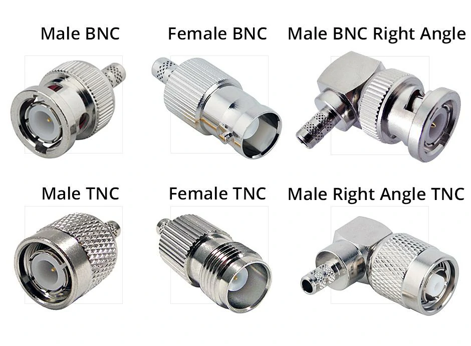
Visual comparison of male BNC, female BNC, right-angle BNC, male TNC, female TNC, and right-angle TNC connector structures. The image helps users identify connector gender and body configuration before selecting a TNC to BNC adapter.
Compare TNC and BNC mechanical interfaces
| Field | TNC | BNC |
| Locking method | Threaded | Bayonet |
| Connection speed | Moderate | Fast |
| Mechanical retention | Higher | Moderate |
| Typical use | Antennas and communication systems | Test and video equipment |
| Common installation concern | Correct thread engagement | Secure bayonet locking |
The TNC side should screw together smoothly. Resistance at the beginning of the thread may indicate cross-threading or an incompatible interface.
The BNC side should engage with a controlled push and twist. It should not feel unusually loose after the bayonet pins reach the locked position.
Damage, contamination, worn plating, or poor machining can create inconsistent contact even when the connector appears to be fully installed.
Match connector gender before selecting an adapter
Gender should be identified from the center contact and mating interface rather than from the outer thread alone.
In a conventional RF connector:
- A male connector normally has a center pin.
- A female connector normally has a center socket.
Possible TNC-to-BNC combinations include:
- TNC male to BNC male
- TNC male to BNC female
- TNC female to BNC male
- TNC female to BNC female
The correct combination depends on the two existing ports. For example, a TNC female equipment port and a BNC female cable connector require an adapter with TNC male and BNC male interfaces.
Reverse-polarity versions require additional attention. A reverse-polarity connector may use the same outer coupling structure but have the opposite center contact. A photograph, engineering drawing, or confirmed part number is safer than choosing from the product name alone.
Check compatibility beyond physical appearance
After confirming connector family and gender, check impedance.
Most radio communication, antenna, and RF measurement systems use 50 ohms. BNC connectors are also widely available in 75-ohm versions for video and broadcast applications. The two versions may appear similar, but their internal conductor geometry is not necessarily the same.
TEJTE’s coaxial connector reference distinguishes 50-ohm and 75-ohm BNC designs and notes that their frequency capabilities can differ.
The operating frequency must also be confirmed. The adapter should cover the highest frequency present in the system, not merely the nominal frequency printed on one piece of equipment.
Other details include:
- Body and contact material
- Surface plating
- Insulator material
- Mating-cycle requirement
- Environmental exposure
- Allowable VSWR
- Expected insertion loss
A properly selected 50 ohm TNC adapter should maintain the intended transmission path without creating an avoidable impedance transition.
How Can You Choose the Correct TNC to BNC Adapter Structure?
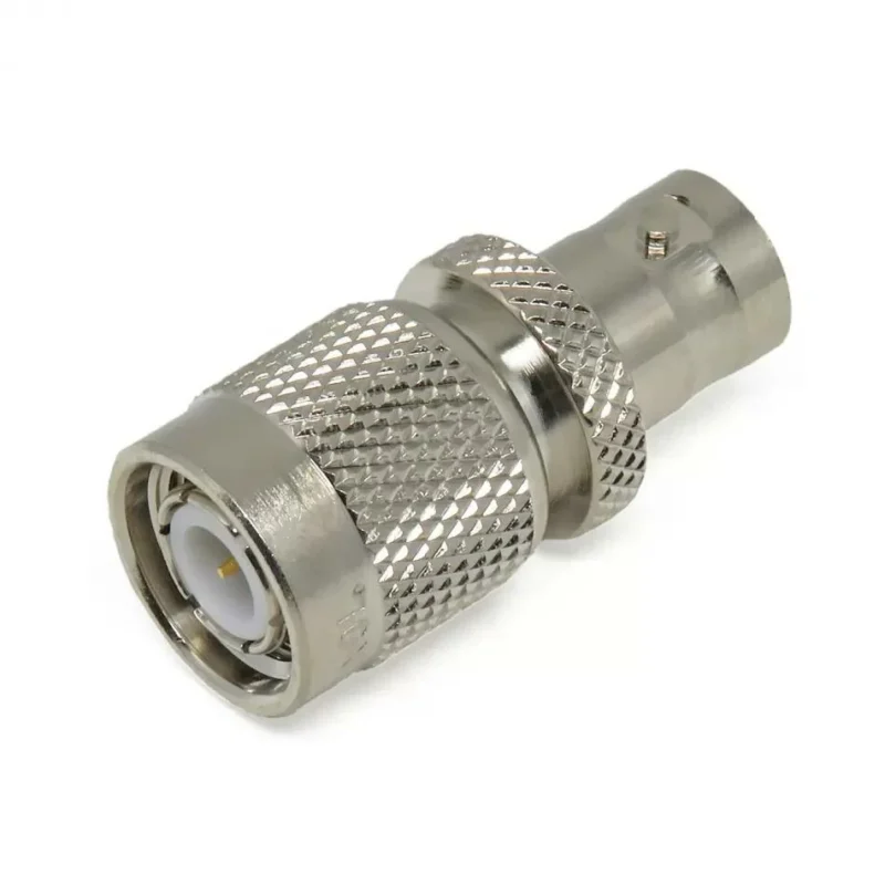
Once the interfaces and electrical requirements are confirmed, the body structure can be selected.
Select straight adapters for general RF connections
A straight adapter creates a direct axial transition between TNC and BNC.
It is normally suitable for:
- Test-bench connections
- Radio equipment
- Antenna evaluation
- Temporary measurement setups
- Cable extension
- Accessible equipment ports
A straight design is compact, but enough clearance must remain behind the equipment for the coaxial cable. A cable should not be forced into a sharp bend immediately behind the adapter.
Use right-angle adapters when installation space is limited
A right-angle TNC adapter redirects the cable by approximately 90 degrees. It may reduce the depth needed behind an instrument or allow the cable to run alongside a panel.
This structure is useful when:
- Equipment is close to a wall
- Rear clearance is limited
- The cable must run parallel to the enclosure
- Connector spacing is tight
- A straight adapter would violate the cable bend radius
The internal path of a right-angle adapter is more complex than that of a straight model. Its specified frequency range and RF performance should therefore be checked rather than assumed.
Choose bulkhead adapters for fixed installations
A bulkhead adapter passes through an equipment panel or enclosure wall. A nut, washer, or flange secures the connector so that internal and external cables can be connected independently.
Panel thickness, mounting-hole diameter, threaded-barrel length, washer arrangement, and chassis grounding should be confirmed before ordering.
TEJTE’s BNC bulkhead connector guide explains how panel dimensions and mounting structure affect a fixed BNC installation.
TNC to BNC Adapter Structure Selection Matrix
| Adapter structure | Recommended application | Main point to confirm |
| Straight | General RF connection | Cable clearance |
| Right angle | Limited installation space | Orientation and frequency rating |
| Bulkhead | Panel or enclosure mounting | Panel thickness and grounding |
| Gender adapter | Correcting interface gender | Pin and socket arrangement |
| Custom cable assembly | Permanent or offset connection | Cable type, length, and strain relief |
The best TNC to BNC adapter is not simply the part that can be attached to both connectors. It must suit the complete installation, including the RF frequency, system impedance, equipment ports, cable direction, mounting space, and expected mechanical load. The article structure and keyword coverage follow the supplied outline.
How Does Impedance Affect TNC to BNC Adapter Performance?
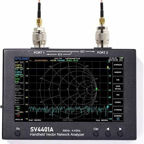
A handheld vector network analyzer connected at both ports for RF testing. This type of setup can measure the return loss, VSWR, and insertion loss of a TNC to BNC adapter across its intended frequency range.
A TNC to BNC adapter may connect smoothly and still introduce an electrical problem. This often happens when the connector families are correct, but the impedance is not.
Most RF communication, antenna, radio, and laboratory measurement systems operate at 50 ohms. BNC connectors, however, are manufactured in both 50-ohm and 75-ohm versions. The 75-ohm design is commonly associated with video and broadcast systems, while the 50-ohm version is normally used for radio-frequency transmission and testing.
The difference is not just a label. The diameter and spacing of the center conductor, dielectric, and outer conductor help determine the characteristic impedance. When a 75-ohm BNC interface is inserted into a 50-ohm RF path, the transition can produce additional reflection.
Match 50-ohm systems before connecting equipment
Before ordering a 50 ohm TNC adapter, check the impedance of every component in the path:
RF source → cable → TNC interface → adapter → BNC interface → load
One incorrect component can disturb the transition even when the other parts are properly matched.
For example, suppose a 50-ohm signal generator is connected to a 50-ohm coaxial cable and a 50-ohm antenna. If the adapter between them uses a 75-ohm BNC structure, the system temporarily changes impedance at that point. Some of the RF energy may reflect toward the source instead of continuing to the antenna.
The result may appear as:
- Higher VSWR
- Lower return loss
- Reduced delivered power
- Irregular frequency response
- Measurement variation
- Unexpected resonance points
At low frequencies, the difference may not be obvious during a basic continuity check. As frequency rises, small geometric changes become more important. That is why a continuity meter cannot confirm whether an adapter is suitable for RF transmission.
TEJTE’s BNC coupler selection guide explains that 50-ohm and 75-ohm BNC components can sometimes mate physically, although their internal geometries are different. Physical mating should therefore never be treated as proof of impedance compatibility.
Understand how frequency range affects adapter selection
An adapter does not have one performance value that remains unchanged at every frequency.
At lower frequencies, a general-purpose adapter may produce little noticeable change. Near its upper operating limit, manufacturing tolerances, contact alignment, dielectric dimensions, and internal conductor transitions have a greater influence.
When evaluating a TNC to BNC adapter, confirm:
- Minimum and maximum operating frequency
- Nominal impedance
- Maximum specified VSWR
- Typical insertion loss
- Connector mating condition
- Test method and reference plane
The usable frequency should cover the entire system band, including test margins. A device operating at 2.4 GHz, for example, should not be evaluated only at 1 GHz because the adapter response may change across the band.
The connector with the lowest practical frequency capability can become the limiting component. A high-frequency TNC connector cannot improve a poorly designed BNC transition on the other side.
TEJTE’s TNC connector reference describes TNC as a threaded 50-ohm connector family valued for secure coupling and vibration resistance. The performance of the finished conversion still depends on the BNC side and the internal adapter structure.
Avoid choosing adapters only by connector shape
Two adapters can look almost identical in a catalog photograph but behave differently in an RF test.
Possible differences include:
- 50-ohm or 75-ohm geometry
- Insulator dimensions
- Contact material
- Plating thickness
- Center-pin alignment
- Body machining accuracy
- Frequency rating
- Environmental sealing
- Mating-cycle durability
The purchasing description should therefore contain more than “TNC to BNC adapter.”
A clearer specification would be:
TNC male to BNC female straight adapter, 50 ohms, DC to 4 GHz, for RF laboratory testing.
This gives the supplier enough information to confirm both mechanical and electrical compatibility.
How Do TNC to SMA and TNC to N Adapters Compare?
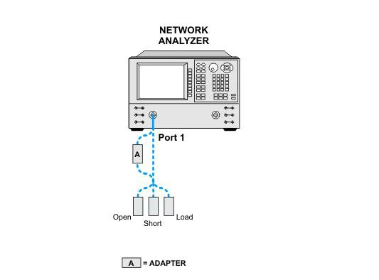
Diagram showing a network analyzer Port 1 calibration setup using open, short, and load standards through an adapter. Correct calibration moves the reference plane closer to the TNC to BNC adapter for more reliable VSWR and return loss measurements.
TNC is not converted only to BNC. Engineers may also use a TNC to SMA adapter or TNC to N adapter, depending on the connected equipment.
The correct conversion is determined by the application, not by which adapter is physically smallest or easiest to purchase.
Choose TNC to SMA adapters for compact RF equipment
SMA connectors are smaller than TNC and BNC connectors. They are frequently used on RF modules, wireless devices, GPS equipment, compact antennas, test boards, filters, amplifiers, and measurement accessories.
A TNC to SMA adapter is suitable when a larger threaded TNC cable or antenna must connect to compact RF hardware.
Typical examples include:
- TNC antenna cable to SMA radio module
- TNC test cable to SMA attenuator
- TNC equipment port to SMA measurement cable
- TNC antenna to SMA wireless receiver
The smaller SMA interface can be convenient, but it is also more sensitive to mechanical force. A thick cable attached through a rigid adapter may place significant leverage on an SMA port.
A short flexible jumper is often safer when the connected TNC cable is heavy or frequently moved. TEJTE’s SMA to TNC adapter guide provides additional guidance on gender direction, straight and right-angle structures, impedance, and installation space.
Choose TNC to N adapters for larger RF systems
Type N connectors are larger and are widely used in antenna systems, base stations, radio equipment, outdoor communication installations, and higher-power RF paths.
A TNC to N adapter is more appropriate when the equipment on the opposite side uses an N-type interface rather than BNC or SMA.
Common connections include:
- TNC radio to N-type antenna cable
- TNC test port to N-type measurement equipment
- TNC cable to outdoor N-type antenna
- TNC device to communication-system feed line
The larger connector body usually provides stronger mechanical support than SMA, but installation clearance must be considered. Type N connectors also require more space for tightening and cable routing.
RF Interface Conversion Decision Table
| Conversion | Typical application | Main selection concern |
| TNC to BNC | Test instruments and laboratory equipment | 50-ohm versus 75-ohm BNC |
| TNC to SMA | Compact RF modules and measurement devices | Port stress and frequency rating |
| TNC to N | Antennas and communication systems | Installation space and cable size |
| TNC to TNC | Gender correction or cable extension | Male/female combination |
| Custom cable assembly | Permanent equipment integration | Cable loss and strain relief |
A BNC conversion is usually chosen for fast-access test equipment. SMA suits compact and higher-density hardware. Type N is commonly selected for larger antenna and communication installations.
How Can a TNC to BNC Adapter Influence RF Signal Quality?
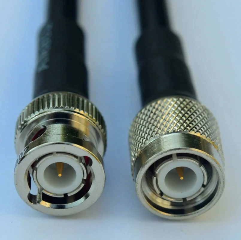
Every connector pair creates a transition. A well-designed transition may have only a small effect, but several adapters connected in series can make the signal path harder to predict.
Evaluate VSWR and return loss changes after conversion
VSWR and return loss describe the amount of mismatch in an RF path.
A perfect impedance match would have a VSWR of 1:1, although real connectors and adapters always introduce some variation. As mismatch increases, more energy is reflected.
Return loss expresses the same reflection behavior in decibels. A larger positive return-loss value generally indicates less reflected energy. For example, a return loss of 20 dB corresponds to approximately 1% reflected power and a VSWR near 1.22:1.
Engineers can use the TEJTE VSWR testing guide to understand how impedance discontinuities appear during cable and connector measurements.
A poor result after adding an adapter may come from:
- Incorrect impedance
- Damaged center contacts
- Loose TNC threads
- Worn BNC bayonet lugs
- Contaminated contact surfaces
- Poor internal geometry
- An unsuitable frequency rating
The adapter should be tested in the same orientation and frequency range planned for the final system.
Consider insertion loss in multiple adapter connections
Insertion loss measures how much signal is reduced while passing through a component. It is normally evaluated using the VNA’s S21 measurement.
A single quality adapter may contribute only a small amount of loss. However, the total effect increases when the path contains several transitions:
Cable → adapter → coupler → second adapter → equipment
Each junction can add conductor loss, contact resistance, dielectric loss, and mismatch loss.
TEJTE’s insertion loss guide explains that insertion loss and return loss should be evaluated separately. A path may transmit most of the signal while still showing an undesirable reflection point.
Reduce unnecessary RF transitions in precision systems
The simplest way to limit adapter-related uncertainty is to reduce the number of transitions.
Good practice includes:
- Use one correct adapter instead of an adapter chain
- Select the required gender from the beginning
- Keep the RF path short
- Support heavy cables mechanically
- Clean contacts before testing
- Tighten threaded interfaces consistently
- Calibrate the VNA at the correct reference plane
- Use a custom cable assembly for permanent connections
When adapters and test cables are positioned between the calibration plane and the device under test, their effects may be included in the result. Reference-plane adjustment or de-embedding can be used in precision measurements when the instrument and available calibration standards support it.
The goal is not to avoid every adapter. A properly selected adapter is a useful engineering tool. The goal is to ensure that each transition has a clear purpose and a known electrical effect.
This section follows the supplied article outline, keyword plan, and chapter structure.
How Should Engineers Test TNC to BNC Adapters Before Use?
A newly received TNC to BNC adapter should not be installed in an RF system without inspection. The adapter may have the correct connector names on the package, but engineers still need to confirm gender, impedance, mechanical condition, and electrical behavior.
Testing is especially important when the adapter will be used in measurement systems. A damaged contact or poorly matched transition can be mistaken for a problem with the antenna, cable, amplifier, or device under test.
Calibration should place the measurement reference planes as close as practical to the adapter. Otherwise, the result may include the loss and mismatch of test cables or additional fixtures. TEJTE’s VSWR testing guide explains how VSWR and return loss describe reflection within an RF connection.
TNC to BNC Adapter Inspection Checklist
| Inspection field | Information to record |
| Product model | Supplier or internal part number |
| TNC interface | Male, female, standard, or reverse polarity |
| BNC interface | Male or female |
| Structure | Straight, right angle, or bulkhead |
| Impedance | 50Ω or 75Ω |
| Frequency range | Required and specified limits |
| Thread condition | Pass or fail |
| Bayonet lock | Pass or fail |
| Center contacts | Aligned, clean, and undamaged |
| DC continuity | Center and outer conductor results |
| VSWR | Maximum result across the band |
| Return loss | Minimum result across the band |
| Insertion loss | Maximum result across the band |
| Final result | Pass, fail, or application review |
Acceptance limits should come from the project specification. There is no single VSWR or insertion-loss limit that is correct for every TNC adapter and every frequency range.
How Should Buyers Specify a TNC to BNC Adapter?
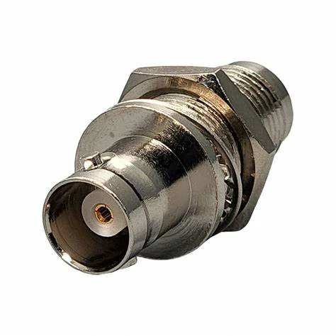
Product image of a TNC female to BNC female bulkhead adapter with mounting hardware. This structure allows a TNC-to-BNC transition to be secured through an equipment panel, cabinet, or RF enclosure.
Many purchasing problems begin with an incomplete description such as:
Need TNC to BNC adapter, 100 pieces.
This does not identify the connector genders, impedance, mounting structure, frequency range, or test requirements. The supplier may provide a part that looks correct but cannot be used in the intended system.
Define connector interfaces before ordering
The buyer should specify both ends separately.
For example:
Connector A: TNC male
Connector B: BNC female
A photograph can support the request, but it should not replace a written interface description. The center pin or socket must be visible, and the buyer should mention whether either side uses a reverse-polarity structure.
The mechanical design must also be defined:
- Straight
- Right angle
- Bulkhead
- Front mount
- Rear mount
- With flange
- Without flange
For bulkhead installation, provide the panel thickness and mounting-hole dimensions. The available space around the connector should also be reviewed because the mounting nut may require more clearance than the adapter body itself.
Add RF specifications to avoid incorrect selection
The minimum RF information should include:
- System impedance
- Operating-frequency range
- Maximum VSWR
- Minimum return loss
- Maximum insertion loss
- Equipment or application
- Expected test method
The operating frequency should reflect the complete band. A buyer should not specify only the center frequency if the equipment operates across a wider range.
The application also gives the supplier important context. An adapter used for temporary laboratory testing may have different mechanical requirements from one installed on a vehicle, outdoor antenna, communication enclosure, or vibrating industrial machine.
For cable-based alternatives, buyers should also specify cable type, length, flexibility, bend radius, shielding requirement, and strain relief. TEJTE’s RF cable guide provides broader guidance on matching coaxial cables to antennas, wireless equipment, and test systems.
Custom TNC to BNC Adapter Specification Template
| Specification field | Buyer’s requirement |
| Adapter type | TNC to BNC |
| Connector A | TNC male or female |
| Connector B | BNC male or female |
| Polarity | Standard or reverse polarity |
| Structure | Straight, right angle, or bulkhead |
| Impedance | 50Ω or 75Ω |
| Frequency range | DC to required maximum frequency |
| Body material | Brass, stainless steel, or project requirement |
| Body plating | Nickel, gold, or specified finish |
| Center contact | Material and plating requirement |
| Insulator | PTFE or specified material |
| Mounting | Panel dimensions where applicable |
| Application | Laboratory, antenna, radio, enclosure, or other |
| VSWR requirement | Maximum accepted value |
| Insertion loss | Maximum accepted value |
| Environmental need | Indoor, outdoor, vibration, humidity, or sealing |
| Quantity | Prototype and production quantity |
| Documentation | Drawing, test report, inspection record, or sample approval |
This template is more useful than sending only a photograph. It gives engineering, purchasing, and production teams the same reference during quotation and approval.
How Are TNC to BNC Adapters Used in Modern RF Systems?
TNC and BNC interfaces remain useful because many current systems must connect new equipment to existing cables, instruments, antennas, and field installations.
Apply adapters in RF laboratory environments
Laboratories rarely contain only one connector family. A test bench may include BNC oscilloscopes, SMA measurement accessories, N-type power equipment, and TNC antenna cables.
A TNC to BNC adapter allows engineers to:
- Connect antenna cables to test receivers
- Evaluate radio outputs with BNC instruments
- Compare older and newer equipment
- Build temporary prototype paths
- Troubleshoot field-returned devices
- Reuse available test cables
The adapter should be included in the measurement review. When precision is important, engineers can compare the test path with and without the adapter or characterize the adapter separately.
Use adapters for antenna and communication equipment integration
TNC connectors are often selected where threaded retention is useful, while BNC ports remain common on test and monitoring equipment. TEJTE’s connector comparison notes that TNC is commonly associated with radios, antenna connections, and communication equipment, while BNC is frequently used for quick-connect test and video applications.
Possible integration paths include:
- TNC antenna to BNC receiver
- TNC radio port to BNC monitoring cable
- TNC enclosure interface to BNC test panel
- TNC communication device to legacy BNC equipment
- TNC outdoor cable to an indoor BNC measurement point
For permanent installations, a bulkhead adapter or custom cable assembly can provide better mounting and strain control than a rigid adapter hanging directly from an equipment port.
Select the adapter based on the complete RF connection path
An adapter should never be selected in isolation. Review the entire route:
Signal source → source connector → coaxial cable → adapter → equipment connector → load
The final choice should account for:
- Connector family and gender
- Impedance
- Highest operating frequency
- Cable size and weight
- Installation clearance
- Mechanical vibration
- Outdoor exposure
- Number of RF transitions
- Required measurement accuracy
A technically correct adapter converts the interface without creating an unnecessary weak point. When the installation needs several adapters, an unusual angle, or permanent routing, a purpose-built TNC-to-BNC cable assembly may be the cleaner solution.
FAQ
Does the adapter affect signal quality?
It can. Any added RF transition may introduce reflection and insertion loss.
Is a custom cable better than a rigid adapter?
A rigid adapter is convenient for temporary direct connections. A cable assembly is often better for permanent routing, offset ports, or reducing mechanical stress.
When should a bulkhead adapter be used?
Use one when the TNC-to-BNC transition must be fixed through a panel, cabinet, or equipment enclosure.
What should be included in a quotation request?
Provide connector gender, polarity, impedance, frequency range, structure, application, quantity, and required RF test values.
