BNC T Connector Guide: Signal Splitting & Termination Tips
Nov 6,2025
Preface
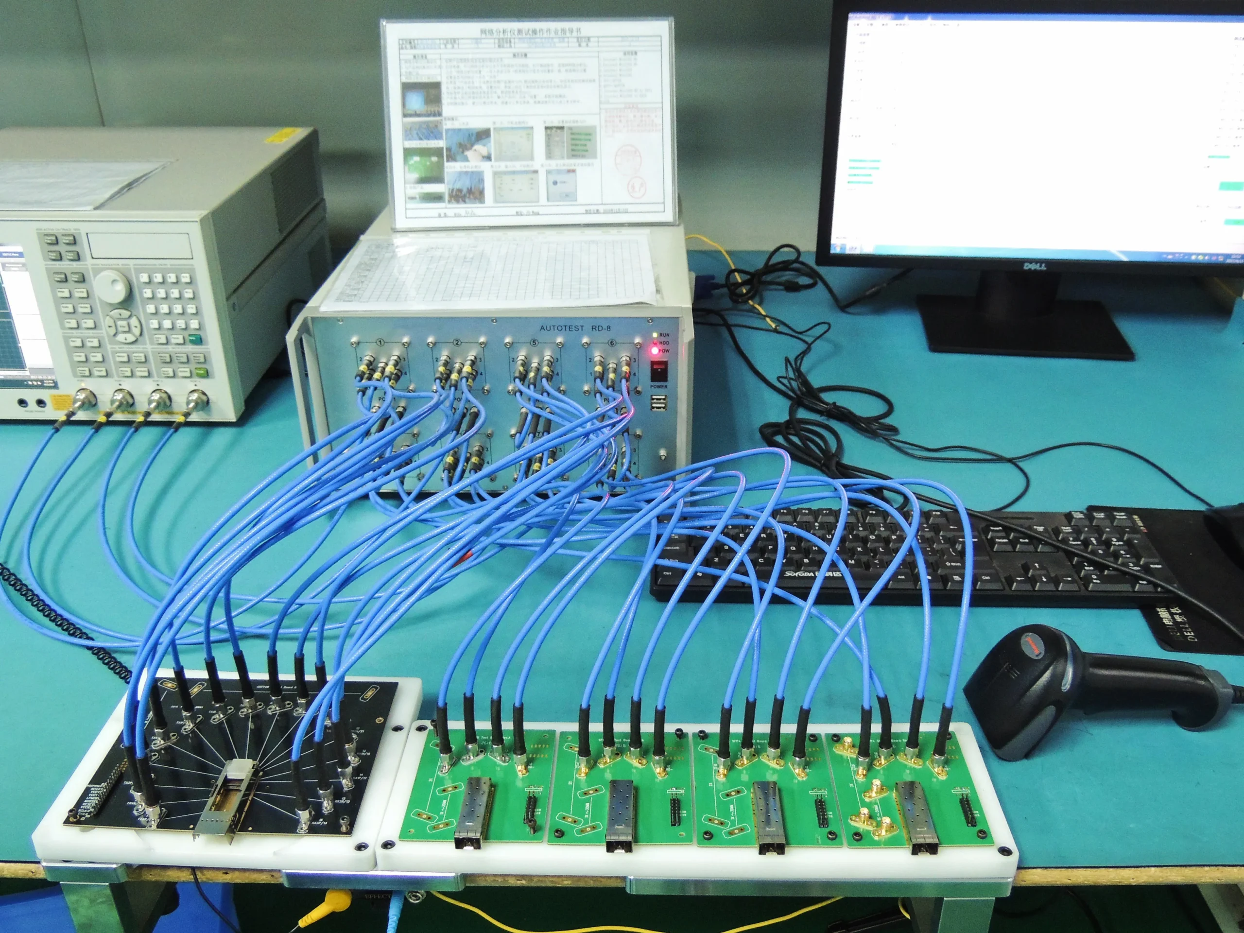
Figure serves as an introductory visual element for the document. Through a common lab measurement scenario – abnormal waveforms on an oscilloscope – it immediately highlights the theme: the seemingly simple BNC T connector can severely impact signal integrity if used improperly.
Every engineer who works with oscilloscopes or RF signal sources eventually faces the same small but annoying puzzle—how to split one BNC signal cleanly between two devices without wrecking impedance balance. That’s where the humble BNC T connector quietly shines.
Unlike an active splitter or amplifier, a T-piece provides an instantaneous mechanical fan-out, ideal for bench testing or synchronization tasks. Yet the simplicity hides a trap: every T changes the load impedance and reflections if you’re careless with termination. This article walks through the practical use of BNC T connectors, using TEJIATE’s precision-machined models (BNC-KKY 75 Ω, BNC-JKKK 50 Ω, BNC-KYB2, BNC-JB3) as real examples. We’ll see when a T is smarter than a splitter, how to preserve 50 Ω or 75 Ω integrity, and which gender/orientation choices prevent adapter stacking on crowded panels.
When should you use a BNC T connector instead of a splitter?
A BNC T connector acts as a passive branching node. It’s ideal when you need to feed a trigger or reference signal to more than one instrument without isolating or attenuating the main path too much. Typical setups include:
- Scope + Analyzer: one branch goes to the oscilloscope, the other to a spectrum analyzer for simultaneous time/frequency observation.
- Trigger Fan-out: distributing a logic or sync pulse to multiple receivers.
- Reference Lines: sharing a 10 MHz standard between devices on the same rack.
In each case, the T saves time compared with resistive or transformer splitters that require extra cables and introduce insertion loss of 3 – 6 dB. However, as frequency rises beyond 2 GHz, reflections accumulate quickly unless the connector has tight mechanical tolerance and consistent impedance.
That’s where parts like TEJIATE BNC-JKKK excel. With a 50 Ω characteristic impedance, DC–4 GHz bandwidth, and ≤0.15 dB insertion loss, its brass-nickel body and gold-plated center pin maintain low return loss even under repetitive coupling. For 75 Ω video chains, BNC-KKY keeps impedance uniform up to 2 GHz, reducing ghosting in CCTV or SDI systems.
How do you keep 50 Ω or 75 Ω termination correct when teeing?
One branch terminated, the other high-Z
Suppose your source and cable system are 50 Ω. If you use a BNC T connector to feed both an oscilloscope and a frequency counter, keep the scope in 1 MΩ input mode (high-Z) and add a 50 Ω terminator on the second branch. The source “sees” a proper 50 Ω load, and both devices get accurate amplitude readings.
When both branches are terminated (50 Ω ‖ 50 Ω = 25 Ω), the source current doubles and the signal amplitude collapses to half. At 1 Vpp input, you’ll see roughly 0.5 Vpp on each branch — a 6 dB drop plus possible reflection.
Typical chains: 50 Ω RF benches vs 75 Ω video
- RF Benches: often use BNC-JKKK or BNC-JB3 (50 Ω DC–6 GHz, ≥1500 V withstand). In this environment, termination accuracy below ±2 Ω is essential for maintaining ≥23 dB return loss.
- CCTV / Broadcast: 75 Ω chains use BNC-KKY with proper 75 Ω terminators at the last monitor input. Mixing 50 Ω and 75 Ω parts introduces about 0.2 reflection coefficient, equating to –14 dB return loss — enough to cause visible ghosting on analog video.
To illustrate, TEJIATE BNC-JB3 maintains ≤1.5 mΩ center-contact resistance and ≤1 mΩ outer-shell resistance, ensuring the split path doesn’t distort high-frequency edges. Its Tri-alloy nickel plating resists oxidation better than plain brass, sustaining impedance balance through 500 mating cycles.
Which gender/orientation prevents extra adapters?
Identify port genders; avoid stacking barrels
Choose BNC T adapter / BNC tee connector forms for tight panels
- Straight T-form: lowest loss, best for open racks.
- Right-angle T: reduces clearance depth behind wall-mounted instruments.
- Short pigtail T: relieves port stress when multiple heavy cables hang from a scope front panel.
For panels with limited spacing, TEJIATE’s compact BNC three-female T (PN 11877) keeps the overall length under 33 mm and side-branch spacing ≤ 9.6 mm, maintaining consistent signal geometry while surviving 500 mating cycles.
Real-Spec Summary for This Section
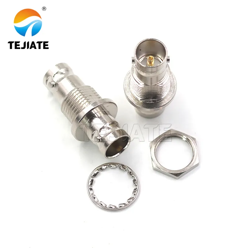
Figure appears in the document as a representative model for 75Ω video applications. It contrasts with the BNC-JKKK, visually emphasizing the necessity of selecting the corresponding T connector for specific impedance systems (50Ω RF vs. 75Ω Video) to prevent signal degradation due to impedance mismatch.
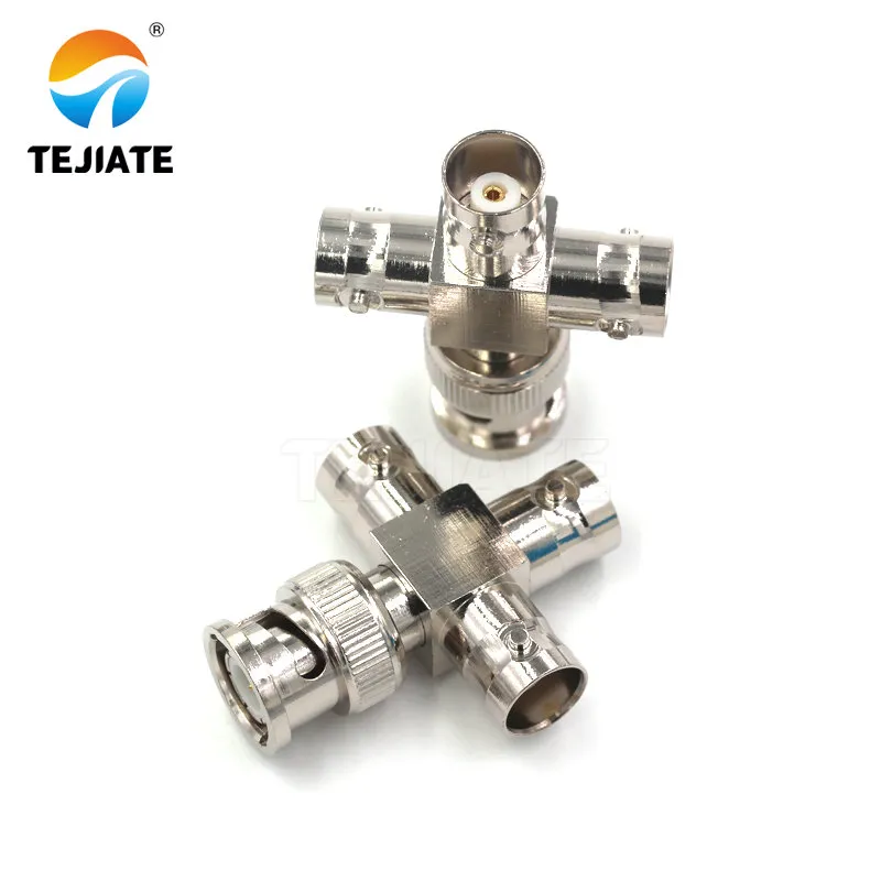
Figure is highlighted in the "Do you need a tee + terminator to loop a signal?" section. It visually presents the key component for solving signal distribution needs. Its feed-through design allows it to provide the correct terminal load for the system while monitoring the signal, making it a fundamental component for building complex test chains.
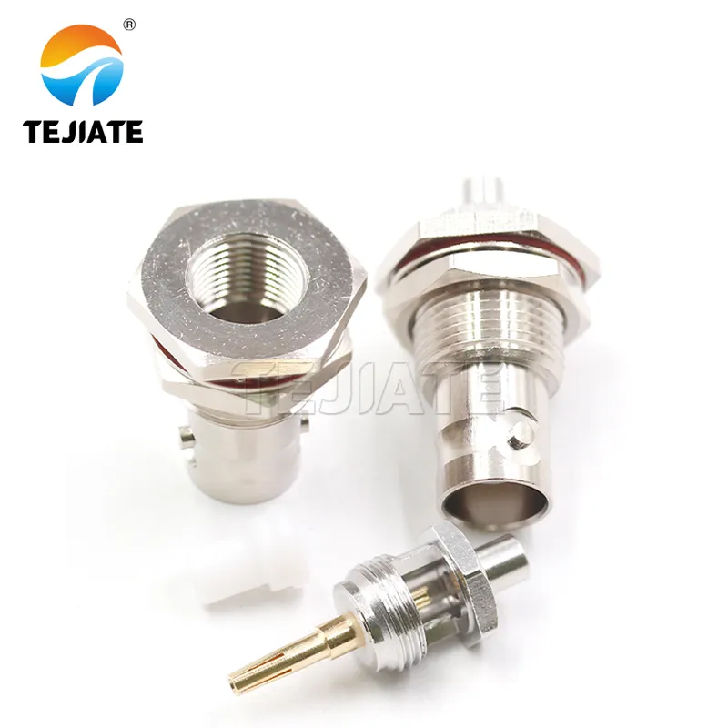
Figure demonstrates another form factor of the T connector – the bulkhead mount type. It is mentioned in the "Which gender/orientation prevents extra adapters?" section and the section on reducing port stress, visually presenting an installation solution suitable for compact panels requiring high mechanical stability.
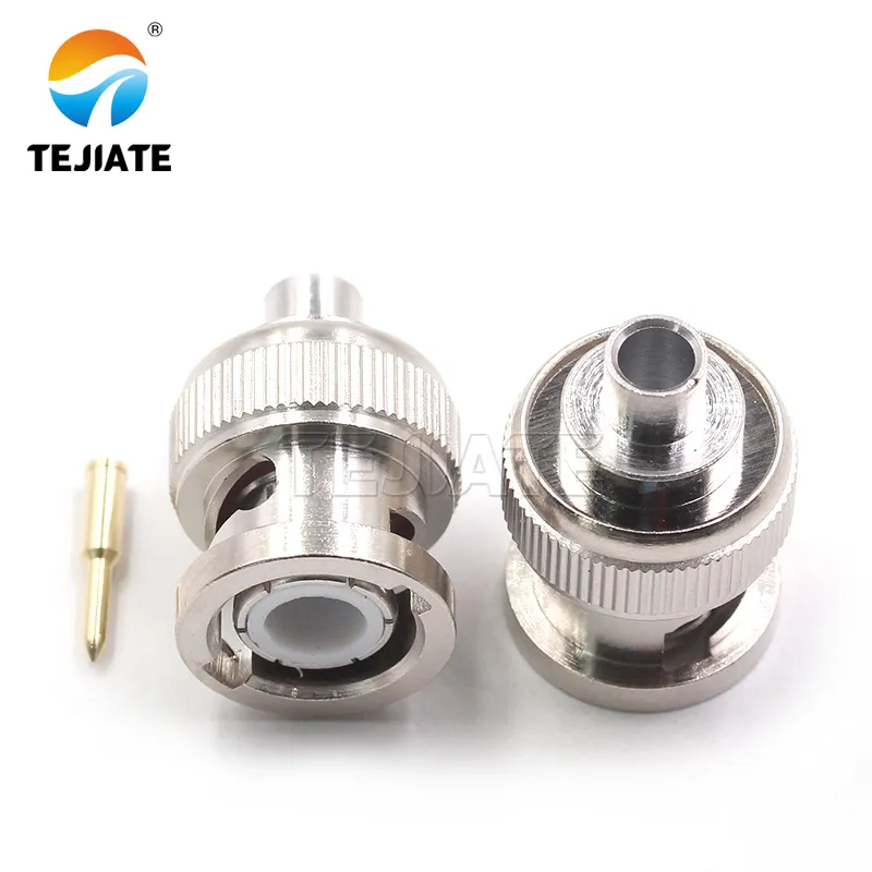
Figure appears in the document as an example of a high-performance T connector. Its DC-6GHz frequency range and excellent voltage withstand/plating characteristics support the discussion in the text regarding maintaining low return loss at high frequencies, high durability, and the differences in tolerance and plating among different brands.
| Model | Impedance (Ω) | Frequency Range | Voltage Withstand | Durability (cycles) | Temperature Range | Material / Plating |
|---|---|---|---|---|---|---|
| BNC-KKY | 75 | 0 – 2 GHz | — | 500 | -45 °C ~ +125 °C | Brass / Nickel |
| BNC-JKKK | 50 | DC – 4 GHz | 1000 V | 500 | -45 °C ~ +125 °C | Nickel + Gold pin |
| BNC-KYB2 | 50 | 0 – 6 GHz | —— | —— | —— | Nickel / RG405 bulkhead |
| BNC-JB3 | 50 | DC – 6 GHz | ≥ 1500 V | ≥ 500 | -45 °C ~ +125 °C | Tri-alloy Nickel / Gold pin |
Do feed-through tees change oscilloscope input behavior?
When you attach a BNC T connector directly to an oscilloscope input, the instrument’s own impedance suddenly becomes part of the equation.
Most modern scopes offer two selectable modes:
- High-impedance (1 MΩ ∥ ≈15 pF) for general voltage probing.
- True 50 Ω input for RF-domain work.
If you install a T-piece on a 1 MΩ input, then terminate one branch with an external 50 Ω load, the signal source sees the correct 50 Ω overall. The oscilloscope itself barely loads the circuit—ideal for measuring while maintaining system balance.
However, if you enable the scope’s internal 50 Ω path and also add an external terminator, the two resistances appear in parallel (25 Ω total). That mismatch doubles the current drawn from your source and cuts signal amplitude in half.
For precise edge or rise-time work above 500 MHz, the dielectric geometry of the T matters. Short, feed-through models like TEJIATE BNC-JKKK (DC – 4 GHz) or BNC-JB3 (DC – 6 GHz) preserve clean transitions. Both use gold-plated brass pins and PTFE insulators with ≤ 1.5 mΩ center-contact resistance—critical when you’re chasing nanosecond-scale distortion.
Practical note: When comparing signals between instruments, always reference the same ground potential through the T body; floating grounds through long adapter stacks can induce common-mode ringing.
(Related reading: the grounding practices section in RF Coax Cable Guide explains loop-current prevention.)
How to size signal levels and loading with a tee
Engineers often ask, “How much amplitude loss should I expect when using a bnc tee connector?” The answer depends on source impedance (Zₛ), branch impedances (Zₐ, Zᵦ), and frequency.
Here’s the core relationship used in TEJIATE’s bench validations:
Calculation Model
[ Z_{load} = \frac{Z_A \times Z_B}{Z_A + Z_B} ]
[ V_{out(each)} = V_{source} \times \frac{Z_{load}}{Z_{source} + Z_{load}} ]
[ Drop(dB) = 20 \log_{10}\left(\frac{V_{out(each)}}{V_{source}/2}\right) ]
Example 1 – Symmetric RF Bench (50 Ω System)
Source: 1 Vpp @ 10 MHz through TEJIATE BNC-JKKK
Branch A → High-Z scope (≈ 1 MΩ)
Branch B → 50 Ω terminator
Effective Zₗ ≈ 50 Ω → No amplitude loss, reflection Γ < 0.02 → Return loss > 34 dB.
Example 2 – Both Branches 50 Ω Terminated
Zₗ = 25 Ω → Voltage drop ≈ 0.5 Vpp (−6 dB).
Reflection Γ = (25 – 50)/(25 + 50) = −0.33 → RL ≈ 9.5 dB → Visible ringing on fast edges.
Example 3 – Video 75 Ω Chain Using BNC-KKY
At 1 Vpp input, two 75 Ω branches yield Zₗ = 37.5 Ω, producing a −3.5 dB level shift and reflected ghosts on monitor feeds.
Hence a single terminated branch with a high-Z monitor is preferred.
| Parameter | Symbol | Typical Value | Measured on |
|---|---|---|---|
| Source Impedance | Zs | 50 Ω ± 1 Ω | Signal Gen |
| Branch A | Za | 1 MΩ || 15 pF | Oscilloscope |
| Branch B | Zb | 50 Ω (terminator) | TEJATE Term Kit |
| Calculated Zi | Zi | ≈ 50 Ω | Nominal |
| Amplitude Drop | — | ≤ 0.1 dB @ 10 MHz | Observed |
Install a tee on a scope the right way
1 – Verify System Impedance
2 – Select Connector Form (Straight or Right-Angle)
3 – Attach the High-Z Branch First
4 – Add Terminator or Feed-Through on the Load Branch
5 – Strain Relief / Short Pigtail if Needed
6 – Continuity & Quick Return-Loss Check
| Step | Tool / Supply | Goal |
|---|---|---|
| 1 | Impedance chart / label | Confirm system Z |
| 2 | Straight / Angle BNC tee connector | Match geometry |
| 3 | High-Z instrument | Prevent double termination |
| 4 | Feed-through terminator | Maintain load while measuring |
| 5 | Short pigtail / tie strap | Relieve strain |
| 6 | Multimeter / VNA | Verify continuity & RL |
Can a right-angle tee or short pigtail reduce port stress?
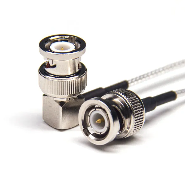
Figure serves as a core illustration in the "Can a right–angle tee or short pigtail reduce port stress?" section. Through a visual mechanical comparison, it effectively argues the importance of selecting the correct physical form of the T connector in dense test racks to ensure long-term connection reliability and signal integrity.
In many bench setups, the physical strain on a front-panel BNC port is far greater than the electrical stress. A rigid bnc t connector hanging from a vertical scope port acts like a small lever arm—especially when two coaxial cables pull in opposite directions. Over time, this torque can loosen the bayonet sleeve or fracture the solder joint behind the jack.
A right-angle bnc t adapter or a short pigtail tee is an elegant solution. The TEJIATE BNC-KYB2 bulkhead type, for instance, allows a short RG405 semi-rigid link that keeps cables parallel to the panel, reducing the moment force by nearly 70 %. Its nickel-plated brass body (12.9 mm nut, ½-28 UNEF thread) ensures the connector holds alignment even under vibration—something often overlooked in mobile test carts or vehicle-mounted diagnostic racks.
When spacing between instruments is tight, a compact bnc tee connector such as BNC-JB3 (20.6 mm body length) is preferred. It maintains 50 Ω impedance through 6 GHz while keeping return-loss degradation below −23 dB. For systems above 3 GHz, any extra mechanical deflection translates directly into micro-impedance shifts, so a flexible pigtail connection is more than a comfort measure—it’s part of signal integrity.
What mistakes silently destroy rise time and return loss?
Even the most expensive generator can’t compensate for bad bench habits. The usual suspects that ruin a clean square-wave trace are subtle—until you measure.
- Mixed 50 Ω / 75 Ω parts. Using a 75 Ω bnc t connector in a 50 Ω RF path introduces ≈ 0.2 reflection coefficient, yielding −14 dB return loss. At 1 Vpp input, this produces visible overshoot and a 0.1 V ripple. Always confirm the connector marking before mating.
- Double termination. Two 50 Ω loads in parallel draw twice the current and halve amplitude. The result looks like “low output,” but the generator isn’t to blame.
- Long adapter stacks. Every additional joint adds ≈ 0.05 dB insertion loss and small dielectric steps that scatter edges. Keep the mechanical path short—one T, one terminator, and one cable.
- Loose nuts and dirty shells. A slightly unseated bayonet ring adds intermittent impedance discontinuities. Periodically clean the pins with isopropyl alcohol and tighten to finger torque.
Real-world measurements with TEJIATE BNC-JKKK and BNC-JB3 show that when properly seated, the rise-time degradation at 1 GHz stays under 5 %. Add one mismatched 75 Ω adapter, and the same signal slows by 15 %—a reminder that mechanical care equals electrical precision.
Additional context: practical termination alignment tips appear in 50 Ohm BNC Terminator Guide.
How do different brands vary on tolerance and plating?
At first glance, all bnc t connectors look identical: shiny metal barrels with three ports. But open them up, and differences in plating, dielectric standoff, and machining tolerance quickly show why not all connectors are equal.
TEJIATE’s manufacturing control keeps center-pin concentricity within ±0.05 mm and maintains full-circle PTFE contact to prevent micro-arcing above 1000 V RMS. Competing low-cost versions often rely on spot-inserted plastic sleeves that shift after repeated insertions, producing minor impedance dips every few gigahertz.
Plating systems also vary.
- Nickel over brass provides good wear resistance but can develop magnetic losses at high frequency.
- Tri-alloy nickel (used in BNC-JB3) minimizes that effect while improving corrosion endurance during 96-hour salt-spray tests.
- Gold-plated pins maintain sub-milliohm contact resistance after 500 mating cycles, essential for repeatable calibration chains.
Environmental sealing is another differentiator. Although a BNC isn’t intended for outdoor IP67 duty (that’s the domain of N-type or SMA bulkhead designs), a tight-fit bnc tee connector with PET or PTFE dielectric resists moisture migration and maintains low dielectric loss across temperature cycles (−45 °C ~ +125 °C).
Field insight: engineers often underestimate how much long-term corrosion shifts the reflection coefficient. A 5 mΩ increase at the pin may look trivial, yet it can raise VSWR from 1.10 to 1.25 @ 1 GHz—enough to mis-calibrate a power sensor.
For system planners building test racks, always document connector plating type and mating count. Mixing dissimilar metals accelerates galvanic wear. By standardizing on consistent bnc t adapters such as TEJIATE BNC-JKKK (nickel-brass body, gold-pin core), your maintenance intervals stretch noticeably longer and measurement repeatability stays predictable.
How should you document split paths for future maintenance?
When a test rack evolves over months, unlabeled tees and cables become an invisible source of chaos. Good documentation turns a messy bench into a repeatable system.
Start with labeling every bnc t connector at the time of installation. Use short tags that record both impedance (50 Ω / 75 Ω) and role—for example: “T-A1 50 Ω → Scope Ref”. Heat-shrink sleeves or laser-printed markers hold up better than tape in warm labs.
Next, keep a rack diagram showing signal direction and termination points. When using bulkhead versions such as TEJIATE BNC-KYB2, note the panel position and thread depth (12.9 mm nut, ½-28 UNEF). Future technicians can remove or replace it without disturbing other lines.
Finally, maintain a change log. Each time you alter a tee, record its location, impedance, and the connected instrument. That tiny habit saves hours of debugging later when a calibration suddenly fails.
Which tee topology should you order for each scenario?
| Use Case | System Z (Ω) | Required Termination | Recommended Form | Notes / Frequency Range |
|---|---|---|---|---|
| Scope + Analyzer share | 50 | One branch terminated, other high-Z | BNC-JKKK (3-female tee) | DC - 4 GHz / compact body reduces VSWR |
| Trigger out → 2 devices | 50 | Both high-Z + one feed-through 50 Ω | BNC-JB3 (DC - 6 GHz) | Use short pigtail if panel crowded |
| Reference distribution (10 MHz standard) | 50 | External 50 Ω terminator only | Right-angle tee / RG405 bulkhead BNC-KYB2 | Keeps ground common, reduces leverage |
| CCTV loop-through video | 75 | Last monitor terminated | BNC-KKY (75 Ω nickel-plated) | 0 - 2 GHz / ghost-free picture |
| Rack mount panel fan-out | 50 or 75 | Check each branch label | BNC tee connector with threaded base | Maintain < 0.15 dB insertion loss |
When ordering, remember that bnc t splitters sold generically online often mix tolerances; select parts with specified impedance and plating data. TEJIATE BNC-JKKK maintains ≤ 1.5 mΩ center resistance and ≥ 1000 V dielectric withstand, ensuring reliable measurements even after 500 mating cycles.
If your setup ever extends beyond 3 GHz or operates outdoors, consider transitioning to SMA or N-type tees—guidance for that crossover appears in SMA to BNC Adapter Lab Integration Guide.
FAQ — Common Questions about BNC T Connectors
1. Will a BNC T connector cut my signal amplitude in half?
2. Can I tee a 50-ohm generator into two instruments without an amplifier?
3. Does a tee work for 75-ohm CCTV lines?
4. How many tees can I chain before it gets ugly?
5. Is a right-angle tee worse than a straight one?
6. Do I need a feed-through terminator with a tee on my scope?
7. What’s the quick check after teeing a path?
Final Note
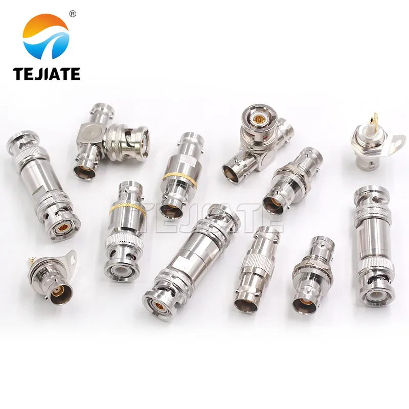
This image is located in the document's final takeaway section, visually echoing the core argument of the entire text. It collectively showcases the key models discussed (e.g., the 50Ω BNC-JKKK and the 75Ω BNC-KKY), symbolizing that selecting well-matched, precision-built, and well-documented T connectors is the ultimate guarantee for building a reliable and predictable measurement system.
A bnc t connector may look trivial, but it decides whether your entire measurement chain behaves predictably. Treat it like a precision component—matched impedance, clean plating, and documented use matter as much as any instrument setting.
Across RF, CCTV, and lab applications, models like TEJIATE BNC-JKKK (50 Ω DC–4 GHz) and BNC-KKY (75 Ω) prove that a well-built tee is not just a connector—it’s a guarantee of signal integrity.
Bonfon Office Building, Longgang District, Shenzhen City, Guangdong Province, China

A China-based OEM/ODM RF communications supplier
Table of Contents
Owning your OEM/ODM/Private Label for Electronic Devices andComponents is now easier than ever.
