MIMO antenna: port mapping, alignment & cable loss
Oct 25,2025
Preface
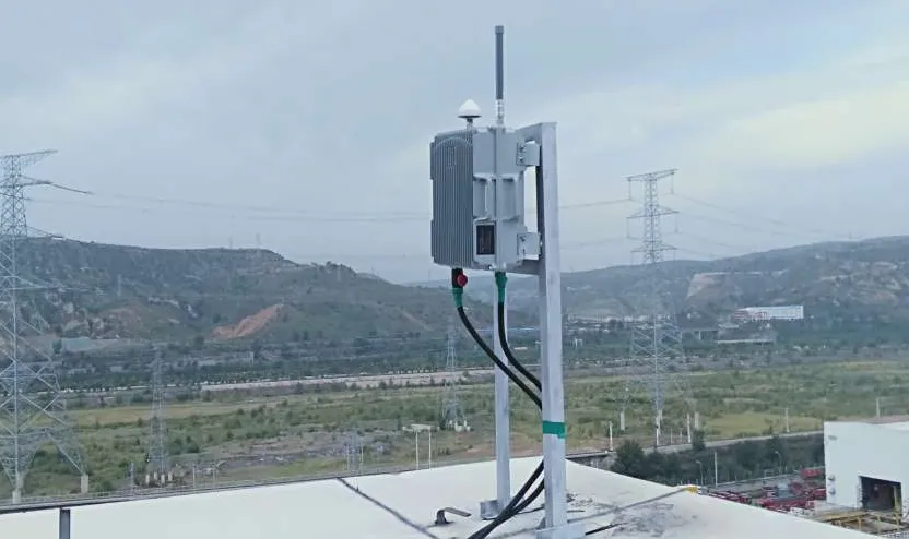
This image highlights the importance of IP67 sealed connectors in ensuring system reliability in real-world harsh environments. Even with perfect cables and antennas, a single unsealed joint can destroy VSWR and flood equipment. This image likely shows installation examples of connectors in outdoor enclosures, antenna masts, or mobile platforms, emphasizing their core value in maintaining clean signals and dry equipment.
Modern LTE and Wi-Fi routers promise “MIMO performance,” yet the hidden variables behind that extra throughput are mostly mechanical—how ports are paired, how antennas are aligned, and how much loss hides inside each coax run. Even a perfect chipset can underperform if one cable path adds 1 dB more loss than the other or if the antennas face different azimuths.
At TEJTE, every MIMO assembly—from the waterproof SMA-KWE bulkhead to LMR-240 jumpers—is designed for 50 Ω consistency, low VSWR, and reliable sealing up to 6 GHz. The goal isn’t just high gain; it’s symmetry. Balanced electrical paths keep each spatial stream in phase, sustaining the SINR that MIMO relies on.
How do you map MIMO antenna ports to your router/AP correctly?
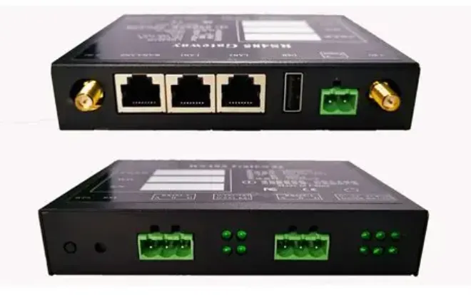
This chart provides a clear visual guide, emphasizing the use of equal-length jumpers and avoiding mixing cable types to maintain amplitude and phase consistency across channels.
When installing a 2×2 or 4×4 MIMO router, the first rule is simple: map each RF port to its dedicated antenna element. On most LTE modems, the primary ports are labeled MAIN and DIV, while Wi-Fi routers show CH0–CH3 or ANT 1–4. Swapping them randomly won’t damage anything, but it can offset phase coherence by several decibels.
2×2 / 3×3 / 4×4 port labels and pairing order
Use equal-length jumpers from the radio to the antennas. For instance, two LMR-240 cables cut to 3 m each will keep path-loss differences under 0.3 dB at 5 GHz (≈ 0.41 dB/m per spec). Avoid mixing RG58 and RG316 in the same pair—the former loses ≈ 0.93 dB/m at 2.4 GHz while RG316 reaches 1.46 dB/m. That imbalance skews received-signal phase and spoils MIMO diversity.
Do you need 2 antennas for LTE MIMO?
Yes—each transmit/receive chain uses its own radiator. A dual-element panel often hides both feeds inside one housing; external Yagis require two separate runs. For single-antenna modems, a simple SISO whip still works, but no amount of firmware tweaking can simulate the spatial paths that MIMO creates.
Many field engineers mark ports with color-coded heat-shrink: red for MAIN, blue for DIV. It’s cheap insurance against mis-routing, especially in outdoor boxes. (For connector orientation references, see TEJTE’s SMA Connector Guide.)
How should you set up and align external MIMO antennas for best SINR?
Mounting geometry defines whether your investment pays off. MIMO antennas need both spacing and polarization diversity; otherwise the streams interfere instead of cooperating. Always check that both cables exit the enclosure cleanly without tight bends below each cable’s minimum radius—RG316 ≈ 15 mm, RG58 ≈ 50 mm, LMR-240 ≈ 30 mm (static)—to keep impedance stable.
How to set up a MIMO antenna / 4G LTE MIMO antenna: azimuth, tilt, spacing
Start by aligning the first antenna toward the serving tower. Mount the second at ±45° polarization or 90° physical separation. For 2.4 / 5 GHz Wi-Fi links, λ is about 12.5 / 6 cm, so a spatial gap of 0.5 λ (≈ 3 cm at 5 GHz) minimizes correlation. When using directional Yagis, keep both elements cross-polarized—one +45°, one –45°—and ensure equal coax lengths within ±5 cm.
How to connect MIMO Yagi antennas: cross-pol vs co-pol, dual-mount tips
If the link runs below 1 GHz, use dual Yagis spaced at 0.6 λ with their booms parallel. Above 2 GHz, compact dual-polarized panels simplify installation and maintain isolation > 25 dB. Use weather-sealed SMA-KWE or SMA-KF bulkheads (rated DC–6 GHz, VSWR < 1.10, insertion loss < 0.15 dB) to pass coax through IP67 enclosures without moisture creep. A small difference of 1 dB in cable loss can reduce effective MIMO gain by over 10 %. When mounting outdoors, reference IP67 Connector O-ring Sealing & Outdoor RF for torque and gasket tips.
Field practice: after rough alignment, check SINR per chain on the modem’s diagnostic page. A balanced setup should show ΔSINR ≤ 3 dB between ports; larger gaps usually mean one feedline has higher loss or a loose connector.
Will a MIMO antenna extend range or mainly stabilize throughput?
Users often expect longer coverage, but MIMO rarely extends range—it stabilizes capacity. Each extra antenna adds a parallel data stream, not extra power. If signal strength at the edge is -90 dBm, two streams at -90 dBm don’t magically become -87 dBm; they simply carry more bits when the channel supports it.
Does a MIMO antenna extend my wireless range? capacity vs coverage trade-offs
Range depends on EIRP and receiver sensitivity, not on how many ports exist. What you gain from MIMO is link stability—fewer retransmissions and higher effective throughput at the same RSSI. For example, a dual-Yagi setup with LMR-240 cables (24.8 dB/100 m @ 900 MHz) maintained a steady -72 dBm RSRP at 5 km, while an RG58 run of equal length fell to -78 dBm. That 6 dB difference halved upload speed despite identical antennas.
Standards note: Which wireless standard operates in both the 2.4 and 5 GHz ranges and uses MIMO?
That would be IEEE 802.11n and newer 802.11ac/ax (Wi-Fi 5/6). These standards implement spatial-multiplexing MIMO with two to eight streams. Each stream needs a dedicated 50-ohm path—matching cables and connectors like TEJTE’s SMA-KE (DC–6 GHz, brass gold-plated housing, VSWR < 1.10) and low-loss LMR-series feedlines keep return loss below -30 dB. For a deeper look at loss sources, see RF Cable Loss: Pick, Budget & Verify at 2.4/5/6 GHz.
In practice, the greatest benefit you notice from MIMO antennas is smoother throughput under interference or multipath conditions. Instead of range doubling, you get a connection that stays usable when a single antenna would fade.
Can you mix connectors and cables without breaking MIMO performance?
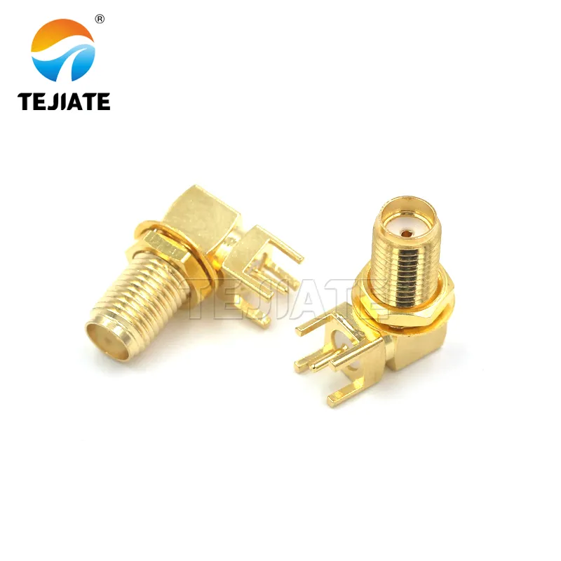
This image details the practice of using SMA connectors as RF interfaces inside space-constrained devices. It likely demonstrates how the connector is mounted through a panel hole, soldered onto PCB pads, and how its right-angle form factor optimizes internal routing to maintain mechanical stability and signal integrity (VSWR < 1.10) in confined spaces. This is crucial for highly integrated MIMO routers or gateways.
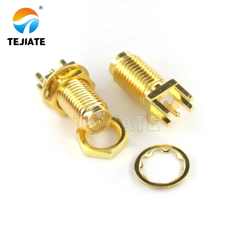
This image helps users select the appropriate connector based on space constraints, frequency requirements, and sealing needs (e.g., IP67), ensuring 50Ω impedance continuity and low VSWR.
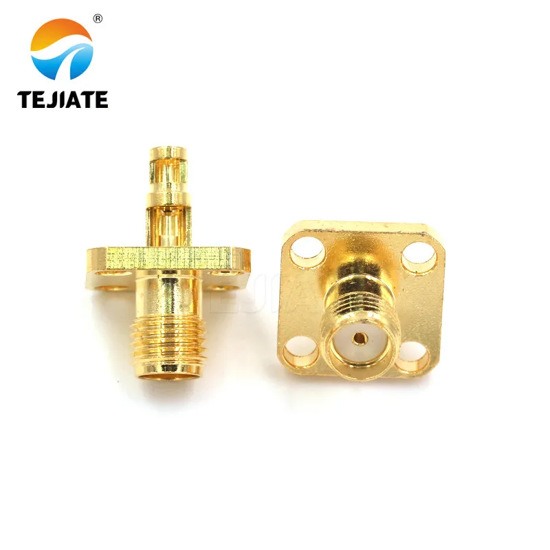
This image visually demonstrates why adapter stacking should be avoided, recommending the use of pre-terminated low-loss jumpers (e.g., LMR-240) to maintain signal path integrity and consistency.
MIMO only works when every RF path behaves the same way. Mixing cable types or mismatched connectors introduces phase delay and reflection that can undo the benefit of spatial streams. In practice, one “bad” jumper is enough to desynchronize the array.
SMA connector / RP-SMA connector / N-type connector: gender & polarity checks
Each path should maintain a continuous 50-ohm impedance. The SMA-KWE right-angle female bulkhead, rated DC–6 GHz with VSWR < 1.10 and insertion loss < 0.15 dB, is ideal for compact outdoor enclosures. The SMA-KF two-hole flange type simplifies panel-mounting on MIMO routers where space is tight, while the SMA-KE straight bulkhead (22.5 mm body, 17 mm thread) keeps alignment perfect through thicker housings.
All three use PTFE insulation and brass gold-plated housings, providing corrosion-free operation up to 6 GHz—important for both 2.4 GHz and 5 GHz Wi-Fi MIMO.
When you must transition between different connector series, limit adapters to one per path. Even a low-loss adapter adds about 0.1 – 0.2 dB and may raise VSWR above 1.20:1. If a layout needs flexibility, use short pre-terminated LMR-240 jumpers rather than multiple adapters; see LMR-240: Loss, Bend & Outdoor Routing for mechanical details.
Adapters vs short jumpers: RF cable loss and VSWR at 2.4 / 5 / 6 GHz
Measured loss per meter varies widely:
How do you route and support cables for long-life IP67 installs?
Even a perfectly sealed IP67 connector can fail early if the cable behind it is poorly routed. Strain, UV, and vibration gradually pull the joint apart. In field tests, most “leaks” originate not from the O-ring but from stress at the cable entry.
To prevent this, follow three principles:
- Gravity control – add drip loops.
Route the coax downward before it enters an enclosure so rainwater drips off rather than flowing into the connector.
- Mechanical relief – use clamps and anchors.
UV-rated cable ties or P-clamps every 30 cm stop whip movement in windy masts. Pair them with vibration-resistant washers under bulkheads.
- Torque management – set and re-check.
Apply 0.6–0.8 N·m to SMA bulkhead nuts, 1.2–1.5 N·m to N-type. Re-torque every six months for equipment exposed to temperature cycling.
Cables such as LMR-240 offer a perfect balance of flexibility and shielding. Its closed-cell PE dielectric prevents water migration, while the bonded foil resists cracking when bent repeatedly. For compact routers or Wi-Fi gateways, RG316 remains a lightweight alternative, especially when paired with SMA-KWE right-angle connectors to relieve pull stress.
Inside panels, anti-rotation tabs on SMA-KE bulkheads keep the connector body from spinning under torque. Adding a star washer between nut and panel distributes pressure evenly, preserving O-ring compression.
An installer’s tip: if your device vibrates—such as in vehicles or industrial robots—secure the jumper near the connector using a foam spacer or flexible boot. It dramatically extends the life of the crimp joint.
For detailed examples of outdoor cable routing and UV protection, TEJTE’s LMR-240 Guide: Loss, Bend & Outdoor Routing shows how different bend radii affect long-term attenuation.
| Cable type | 2.4 GHz | 5 GHz | Notes |
|---|---|---|---|
| RG316 | 1.46 dB/m | 2.15 dB/m | Ultra-flexible, 15 mm bend radius |
| RG58 | 0.93 dB/m | 1.05 dB/m | Economical, 50 mm bend radius |
| LMR-240 | 0.26 dB/m | 0.41 dB/m | Low-loss, dual-shield design |
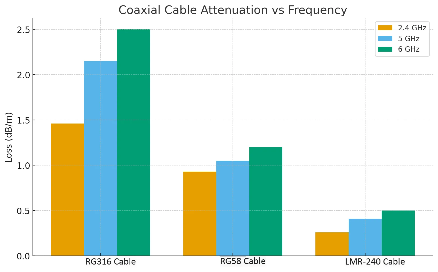
This chart, based on TEJTE verified data, is a key tool for selecting cable types in MIMO systems and calculating maximum allowable lengths, aiming to maintain loss balance between paths.
How long can each path be before cable loss cancels MIMO gains?
MIMO gain depends on maintaining similar amplitude and delay across channels. If one path is longer by even a few meters, extra attenuation and propagation delay can collapse spatial multiplexing.
Pick RG316 / RG58 / LMR-240 by length and bend radius; keep paths equal-length
When both antennas sit close to the modem, RG316’s 2.5 mm diameter is convenient and tolerates frequent flexing. But once a run exceeds 1 m, RG58 or LMR-240 should take over. According to TEJTE’s verified attenuation data:
- RG316: 1.46 dB/m @ 2.4 GHz → best < 1 m
- RG58: 0.93 dB/m @ 2.4 GHz → safe ≤ 3 m
- LMR-240: 0.26 dB/m @ 2.4 GHz → practical ≤ 10 m
Keep total length difference within ±5 cm and loss Δ ≤ 0.5 dB between paths. These small tolerances ensure both data streams arrive within the coherent window of the modem’s MIMO processor.
When to relocate the radio instead of extending cables
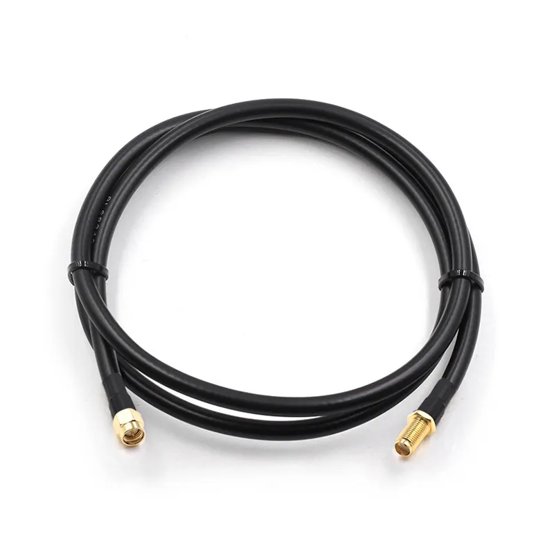
This image emphasizes the importance of managing cable loss at high frequencies (e.g., 5GHz/6GHz), illustrating that sometimes using a longer Ethernet cable (PoE) is more beneficial than extending RF cables for maintaining MIMO performance.
Every extra meter after 5 GHz costs dearly. Suppose each LMR-240 jumper is 5 m long: total ≈ 2 dB loss including connectors. Doubling the length adds another 2 dB, often erasing any MIMO gain. At that point, mount the modem closer to the antennas and run a longer Ethernet line instead. The higher DC voltage drop of PoE is easier to manage than RF loss at 6 GHz.
A practical field rule: if cable attenuation exceeds 3 dB per path, expect MIMO throughput to fall below 70 % of spec. Check our RF Cable Loss Guide for frequency-based formulas used by TEJTE engineers to size equal-length jumpers.
Should you choose panel, Yagi, or ceiling MIMO for this site?
The antenna form determines polarization, coverage, and physical spacing. There is no “one-size-fits-all” MIMO array—indoor routers, outdoor CPEs, and enterprise access points all need different geometries.
What are MIMO ceiling-mount antennas? indoor AP scenarios and plenum routing
In offices or smart-home deployments, a ceiling-mount panel integrates two cross-polarized elements inside one radome. Feed cables usually terminate with RP-SMA plugs that connect directly to the router’s internal MIMO ports. Short RG316 pigtails (≤ 0.5 m) minimize loss and easily snake through conduits. Since these setups operate in 2.4 GHz and 5 GHz bands, each port must stay 50 Ω matched. TEJTE’s SMA series connectors, with PTFE insulators and gold-plated bodies, provide that precision and maintain return loss > 30 dB across both bands.
Outdoor panel vs dual-Yagi: isolation, wind load, mounting hardware
For long-distance links or 4G LTE backhaul, directional arrays outperform ceiling panels. Dual Yagi MIMO antennas—each with 8 to 11 dBi gain—deliver strong SNR when pointed at the base station. Ensure polarization isolation > 25 dB and a rigid mast to prevent phase drift in wind. The feedlines should use weather-sealed SMA-KWE or N-type female bulkheads through the cabinet wall. Both are IP67-rated, tested to 1000 V rms withstand voltage and > 5000 MΩ insulation resistance, ensuring reliability in humidity or salt fog.
Use wide washers and torque evenly to prevent panel tilt. The most reliable field installations bond both connectors to a common ground lug to reduce lightning-induced transients—techniques outlined in TEJTE’s IP67 Connector Outdoor Guide.
Will this setup work at 6 GHz—and what about mmWave constraints?
The jump from 5 GHz Wi-Fi 6 to 6 GHz Wi-Fi 6E or 7 adds only one more gigahertz—but that extra GHz changes nearly everything. Cable loss rises roughly 15 %, connectors become more critical, and every millimeter of phase mismatch matters.
How many antennas in 4×4 MIMO / massive MIMO? consumer vs base-station context
Consumer routers seldom exceed 4×4 MIMO, with four RF chains covering both 2.4 and 5/6 GHz bands. Base stations can scale to 64×64 massive MIMO arrays, but those rely on internal beamforming rather than discrete coax. At the installer level, your task is preserving symmetry between the four external ports.
LMR-240 still performs well up to 6 GHz (VSWR < 1.20, loss ≈ 0.41 dB/m). For short patch runs inside cabinets, RG316 remains acceptable (2.34 dB/m @ 6 GHz) when both paths are identical. Always torque SMA connectors to 8 lbf·in to avoid microscopic gaps that degrade return loss. TEJTE’s SMA-KE straight bulkhead connector with brass gold-plated housing and PTFE insulator holds insertion loss < 0.15 dB up to DC-6 GHz—ample for Wi-Fi 6E and sub-6 5G systems.
Do mmWave MIMO antennas use daughter boards? why DIY upgrades are limited
Above 24 GHz, signals no longer travel through coax like RG316 or LMR-240. PCB traces and waveguide launchers take over. Massive MIMO mmWave arrays integrate hundreds of patch elements on a single substrate. For that reason, DIY upgrades stop at 6 GHz. Still, pre-6 GHz hardware can deliver excellent multi-band coverage when paired with equal-length TEJTE low-loss jumpers and IP67 bulkhead feed-throughs.
Can you verify a MIMO install in the field without lab gear?
Yes—modern modems and routers include diagnostic pages that reveal MIMO status and signal balance. You don’t need a spectrum analyzer to confirm phase symmetry; simple readings and cable-swap tests tell most of the story.
Quick checks: RSSI per chain, modem MIMO flags, cable-swap symmetry test
Connect each antenna and record RSSI and SINR for each chain. If the difference exceeds 3 dB, swap the two coax leads. If the weaker reading moves with the cable, you know loss or connector mismatch is to blame. Inspect the SMA center pins for bending and ensure threads seat flush against the bulkhead nut. The SMA-KWE right-angle connector’s VSWR < 1.10 helps keep these imbalances rare, but field handling can still loosen them.
How to align MIMO antenna with phone apps / compass; acceptance criteria
Mobile apps like Network Cell Info Lite or WiFi Analyzer show SINR and RSRP per chain. Rotate the antennas until both streams peak within 2 dB. Accept the installation only if RSSI values are balanced and VSWR remains below 1.2:1. For professional setups, TEJTE recommends a post-installation record of RSSI, RSRP, and cable length for future maintenance. These metrics are part of the same discipline outlined in the company’s RF Cable Loss Guide.
A practical tip: label each jumper with its measured loss at 2.4 GHz and 5 GHz. That tiny habit pays off months later when you’re debugging why one link drops speed under rain or heat.
Order once: which MIMO antenna + cable + connectors should you buy?
MIMO Port–Cable–Connector Mapping Matrix
| Router / AP Ports | Antenna Type | Connector / Ends | Cable Type | Est. Loss @ 2.4 / 5 / 6 GHz (dB/m) | Path Length / Δ Loss | Adapter Policy | Suggested TEJTE P/N |
|---|---|---|---|---|---|---|---|
| 2×2 | Dual panel or Yagi ±45° | SMA-KE bulkhead M – SMA female | LMR-240 | 0.26 / 0.41 / 0.45 | ≤ 5 cm / ≤ 0.5 dB | 0 | TEJTE-LMR240-2M |
| 3×3 | Ceiling panel MIMO | RP-SMA M – RP-SMA F | RG58 | 0.93 / 1.05 / 1.20 | ≤ 3 cm / ≤ 0.4 dB | 1 (short jumper) | TEJTE-RG58-1.5M |
| 4×4 | Outdoor sector array | N female – SMA-KWE R/A | RG316 | 1.46 / 2.15 / 2.34 | ≤ 2 cm / ≤ 0.3 dB | 1 | TEJTE-RG316-0.8M |
All connectors use PTFE insulators and brass gold-plated housings rated DC–6 GHz, 1000 V rms withstand voltage, and > 5000 MΩ insulation resistance.
This matrix shows that short, low-loss lines matter more than gain alone. If path lengths exceed budget, move the radio instead of adding extensions—a lesson proven through TEJTE field tests with dual Yagi setups.
How much speed do you lose to cable and adapters—should you change the layout?
MIMO Link-Budget Estimator
Inputs:
f ∈ {2.4, 5, 6 GHz}; each path length Lᵢ (m); cable type ∈ {RG316, RG58, LMR-240}; adapters nᵢ
Constants:
adapter_loss ≈ 0.1 dB each; connector_end ≈ 0.2 dB pair;
α(f, cable): use attenuation values from TEJTE data above.
Formula:
Lossᵢ = α(f, cable) × Lᵢ + nᵢ × adapter_loss + connector_end
Outputs:
- Path loss (dB) for each chain
- Δloss and Δdelay between chains
- Predicted throughput vs ideal (%)
- Optimization advice (“Shorten path B by 0.5 m or upgrade to LMR-240”)
Example: At 5 GHz, two LMR-240 paths each 5 m long with one adapter return ≈ (0.41×5 + 0.1 + 0.2)= 2.35 dB loss. If one path were RG58 (1.05 × 5), total 5.45 dB, Δ≈ 3.1 dB—enough to drop MIMO throughput by ≈ 25 %. Equal loss is the true goal.
FAQs
1. How do I wire two external antennas to a 2×2 LTE modem without mixing ports?
Follow the MAIN/DIV labels and use equal-length LMR-240 jumpers terminated with SMA-KE bulkheads. Keep loss difference < 0.5 dB to preserve MIMO gain.
2. Will a MIMO panel actually boost range, or just stabilize weak links?
Mostly stabilization—MIMO improves throughput under fading but doesn’t increase radiated power. The range limit still depends on EIRP and receiver sensitivity.
3. What spacing/orientation should I use for two Yagis—cross-pol or parallel?
Cross-polarize (±45°) for LTE and Wi-Fi. Parallel mount reduces isolation and hurts diversity. Maintain 0.5 λ spacing.
4. How long can each coax be before MIMO gains disappear—RG316 cable vs RG58 cable vs LMR-240 cable?
Keep RG316 < 1 m, RG58 < 3 m, LMR-240 ≤ 10 m. Beyond that, attenuation erases phase balance.
5. Can I use RP-SMA adapters with SMA ports without hurting performance?
Yes if tightened properly, but every adapter adds ≈ 0.1–0.2 dB loss. Prefer single-piece cables whenever possible.
6. What quick field checks confirm my MIMO install is working (no lab gear)?
Compare RSSI/SINR per chain and swap cables. ΔRSSI < 3 dB means paths are balanced.
7. Does 6 GHz Wi-Fi require different antennas or cables than 5 GHz?
No major hardware change—just use low-loss lines like LMR-240 and precision connectors such as TEJTE SMA-KE or N-type rated to 6 GHz.
Closing Note
Bonfon Office Building, Longgang District, Shenzhen City, Guangdong Province, China

A China-based OEM/ODM RF communications supplier
Table of Contents
Owning your OEM/ODM/Private Label for Electronic Devices andComponents is now easier than ever.
