SMA Connector Guide: Selection, Polarity & MIMO Setup Explained
Oct 21,2025
Preface
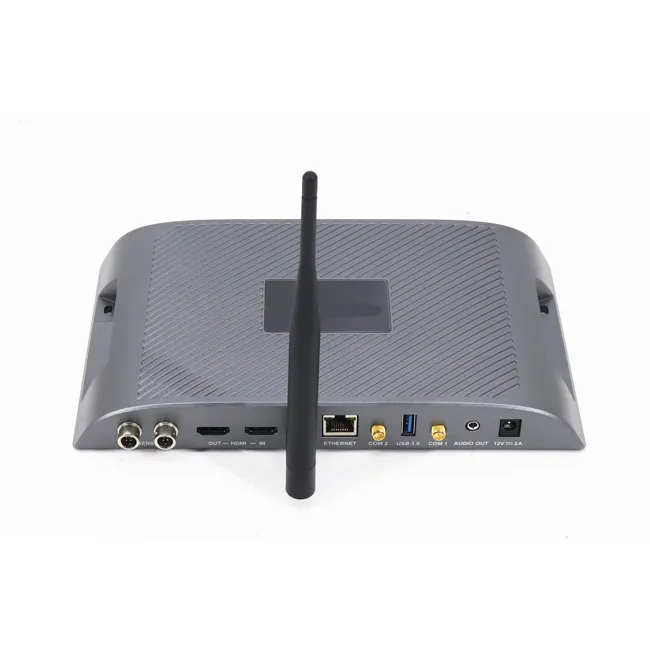
This image shows an actual application product, such as a compact Wi-Fi router, IoT gateway, or RF module, featuring one or more SMA connector ports integrated into its housing. The image clearly displays the physical layout and installation of the SMA interfaces on the product, visually demonstrating the critical role of SMA connectors in various modern RF devices, "from tight indoor routers to weather-exposed IoT gateways." It is the tiny but vital mechanical link connecting the internal radio to external antennas.
In modern RF and Wi-Fi builds, SMA connectors are the tiny mechanical links that quietly determine whether your signal chain runs clean or falls short. They sit between your radio and antenna, handling everything from tight indoor routers to weather-exposed IoT gateways. The wrong choice—wrong polarity, weak sealing, or mismatched plating—can turn a solid design into a noisy one.
Within TEJTE’s portfolio, options range from compact brass-gold SMA-JKW right-angle connectors to rugged stainless-steel SMA-KWK couplers and IP67 bulkhead types like N/SMA-KKF waterproof flanges. All use PTFE dielectric, follow RoHS compliance, and keep VSWR ≤ 1.20 @ 6 GHz with insertion loss ≤ 0.15 dB through hundreds of mating cycles. Their frequency coverage reaches DC–6 GHz or, in some stainless models, up to 18 GHz—enough for dual-band Wi-Fi 6E and 5 GHz backhaul radios.
Before diving into selection, it helps to confirm two basics: who owns the pin and where the seal sits.
How do you identify SMA connector gender and avoid RP-SMA mix-ups?
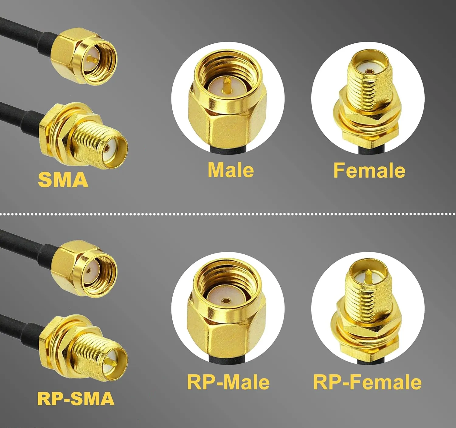
This diagram clearly compares the gender definitions and physical structures of standard SMA and Reverse Polarity (RP-SMA) connectors. It explicitly labels the differences in the position of the center pin and dielectric (PTFE) for SMA Male, SMA Female, RP-SMA Male, and RP-SMA Female – for instance, a standard SMA Male has a center pin, whereas an RP-SMA Male does not. This visual comparison is key for quick identification and avoiding mix-ups, helping users understand the pin and thread ownership to prevent high VSWR or connection failures due to polarity errors.
Pin/dielectric tells for SMA vs RP-SMA connector in seconds
Here’s the quick inspection most engineers rely on:
- Standard SMA-male → center pin present; threads on the inside.
- SMA-female (jack) → recessed socket, white PTFE visible; threads outside.
- RP-SMA-male → no center pin, just dielectric; threads inside.
- RP-SMA-female → center pin inside, threads outside.
You can spot this without tools—just a glance down the barrel. TEJTE’s RPSMA-JK (Part No. 08969-08975-08974) follows that reversed structure precisely. It’s rated DC-6 GHz, insertion loss ≤ 0.15 dB/6 GHz, and return loss > 20 dB, built with a brass gold-plated shell and beryllium-bronze contact for stable grip across temperature swings from –65 °C to +165 °C.
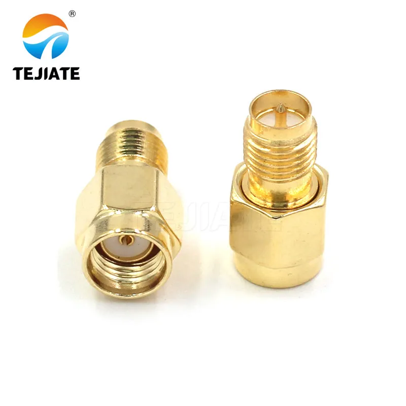
This image is a physical product photo of the specific TEJTE model RPSMA-JK (Part No. 08969, etc.) connector. It concretely shows the actual appearance of a Reverse Polarity SMA connector, whose structure aligns with the RP-SMA definition described in Figure 2 (e.g., RP Male lacks a center pin). This image connects the abstract concept of polarity with a real product, helping users confirm the RP-SMA components they are looking at or need to order, and understand its characteristics such as suitability for DC-6GHz, low insertion loss, and high-temperature stability.
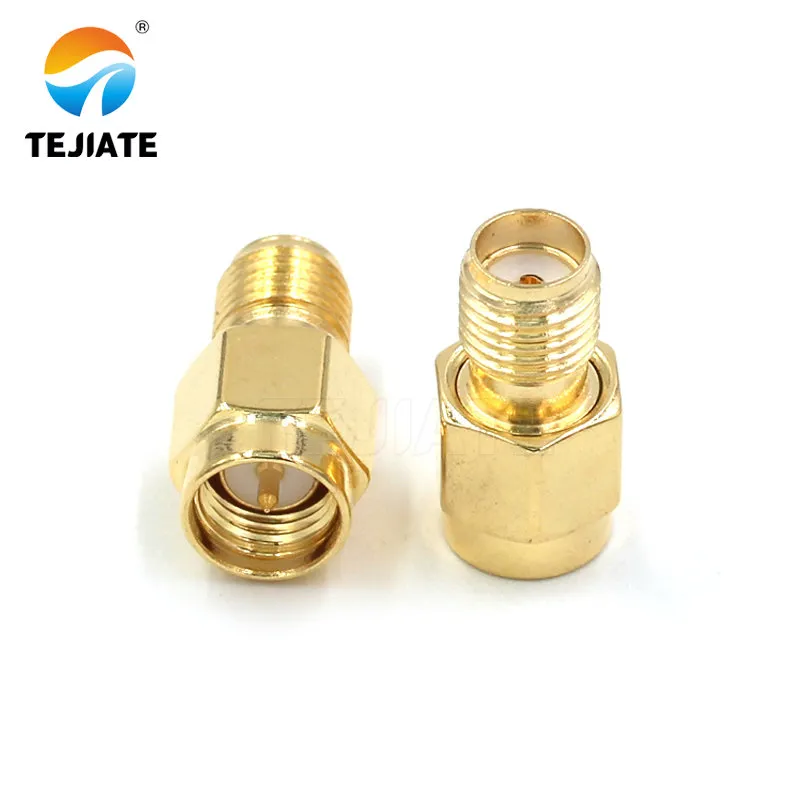
This image shows a physical photo of the TEJTE standard SMA connector model SMA-JK (Part No. 08975). It represents a standard SMA interface component, whose physical characteristics (e.g., presence/absence of center pin, thread type) should conform to the definition of standard SMA in Figure 2. This image provides users with a concrete visual reference for standard SMA connectors, commonly used for regular connections on the device side or antenna side, forming a direct contrast with the RPSMA-JK and facilitating correct selection and matching based on equipment port types.
Device-side vs antenna-side labeling traps and quick sanity checks
Mislabeling happens because some datasheets name gender by the pin, others by the thread. When connecting an RF module to an external antenna, remember:
- Radio side—usually SMA-K (female thread, no pin).
- Antenna side—generally SMA-J (male pin, inner thread).
- Check color rings or coding when assembling 2×2 or 4×4 MIMO panels.
If you skip this check, an RP-SMA antenna on a standard SMA radio leaves the signal path open. That mismatch can lift return loss above 25 dB, cutting link margin by several decibels. A quick polarity inspection saves both cables and sanity.
For more detailed pin mapping, see the related RP-SMA Connector Guide.
Which SMA connector variant fits your environment—standard, bulkhead or IP67 connector?
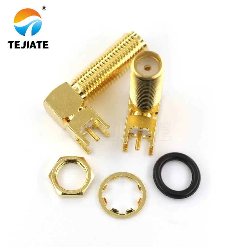
This image is a physical photo of the TEJTE SMA-KWE model connector. The SMA-KWE is a variant of the SMA connector, typically designed for panel mounting or other specific form factors. The document mentions its use in IP67 sealing (with O-rings) or as a bulkhead jack on 4x4 MIMO routers. This image shows the specific appearance of this model, helping users identify this type of SMA connector often used in scenarios requiring certain environmental adaptability or specific mounting methods.
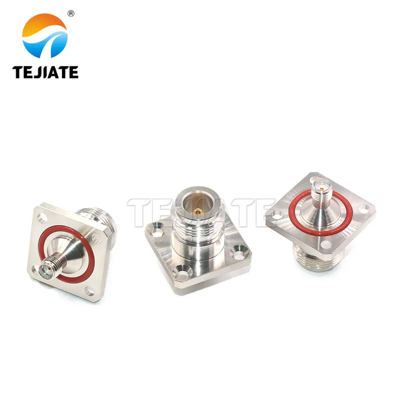
This image shows the physical appearance of the TEJTE N/SMA-KKF waterproof flange connector. This is a key hybrid interface solution, with one end being N-type (typically female) and the other end SMA (typically male or female), featuring a flange for IP67-rated sealed mounting. The image displays its rugged construction and sealing design (e.g., O-ring grooves, flange), suitable for outdoor environments. It allows an SMA interface on the device side to transition via a short jumper to a more robust and better-sealed N-type interface on the antenna side, thereby reducing mechanical stress and improving long-term reliability.
O-ring placement, thread engagement, and torque sequence for sealing
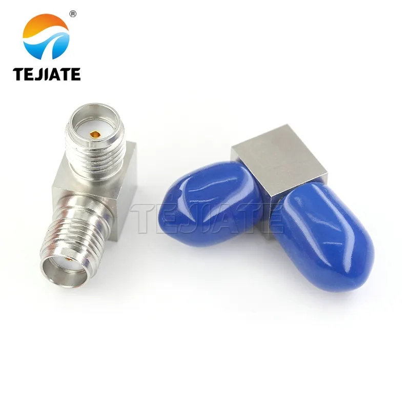
This image is a close-up physical photo of the TEJTE SMA-KWK stainless steel connector. It highlights the connector's characteristic of being manufactured from stainless steel, which offers better corrosion resistance compared to brass, making it suitable for marine, rooftop, or other outdoor environments exposed to harsh weather and UV radiation. The image likely shows its rugged shell and potentially higher performance specifications (e.g., DC-12.4 GHz frequency range, >1000 mating cycles). This image helps users identify this high-durability SMA connector variant designed for demanding conditions.
Waterproof models such as SMA-KWE-1.13 and N/SMA-KKF IP67 use silicone O-rings (grade 6146) positioned behind the bulkhead nut. Correct installation keeps moisture out without crushing the insulator:
- Finger-tighten until the gasket contacts the panel evenly.
- Apply torque—about 0.45 N·m for brass, 0.56 N·m for stainless.
- Stop once resistance increases; overtightening can shift the PTFE core, raising VSWR.
For marine or rooftop mounts, stainless designs like SMA-KWK (Part No. 35518) hold up far better. These run DC-0 to 12.4 GHz, with contact resistance ≤ 5 mΩ, insulation ≥ 5000 MΩ, and durability > 1000 cycles.
Indoors rack vs rooftop mast: plating, corrosion, and re-torque intervals
Indoor racks thrive with gold-plated brass connectors—low resistance and easy to service. Outdoor gear faces UV, rain, and thermal cycling; corrosion becomes the silent killer. Nickel-plated or stainless units like the N/SMA-KKF flange keep conductivity stable between –45 °C and +125 °C and handle 1000 V rms withstand voltage.
For maintenance, retighten every six months if exposed to vibration or temperature extremes. Even a ⅛-turn correction can restore several decibels of return-loss margin.
A full catalog of sealed variants is available under the SMA Connector IP67 Bulkhead Series on tejte.com, including SMA-KWE, KWK, and waterproof SMA/N assemblies.
Will your MIMO antenna layout change the SMA ends and spacing you need?
2×2 / 4×4 port mapping: SMA male/female pairing and color or keying schemes
In typical 4×4 Wi-Fi 6 routers, each radio chain ends in an SMA-KWE bulkhead jack mounted through the housing wall, paired with short SMA-male jumpers or SMA-to-SMA adapters (SMA-KKF, Part No. 08765) leading to the antennas.
Good assembly habits include:
- Label ports A–D or color-tag cables.
- Keep length tolerance within ±5 mm across all four pigtails.
- Use 50 Ω LMR-200 or RG316 coax—each adds roughly 0.15 dB/m @ 5 GHz.
A 5 mm cable mismatch translates to ~10 degrees of phase shift at 5 GHz, enough to degrade beamforming alignment. TEJTE production maintains ±5 mm tolerance to hold array coherence.
Cable dressing for equal length, phase tracking, and strain relief
Inside compact gateways, route pigtails in mirrored paths and avoid bends tighter than each cable’s minimum radius—20 mm for RG316, 25 mm for LMR-240. Secure them with flexible ties rather than hard clamps to prevent pin rotation.
Equal mechanical stress also helps preserve phase stability. If you later upgrade the antenna to an N-type connector, re-verify length—each N-interface adds about 30 mm to electrical path length.
Should you transition to N-type connector or stay on SMA for outdoor runs?
When N-female at the antenna + SMA at the radio lowers stress and loss
One common hybrid solution is to mount an N-female connector at the antenna and keep SMA-female or SMA-male ports on the radio side. A short SMA–to–N pigtail handles the transition without pushing the SMA threads to their limits. TEJTE’s N/SMA-KKF waterproof flange (Part No. 40420) was designed exactly for this purpose:
- Impedance: 50 Ω
- Frequency range: DC–6 GHz
- VSWR: ≤ 1.2
- Withstand voltage: 1,000 V rms
- Durability: 500 cycles
- Temperature range: –45 °C to +125 °C
Pairing this flange with an indoor SMA-KWE feedthrough maintains low reflection while relieving the radio chassis from mechanical stress. That small structural decision can improve field longevity by years, especially in tall outdoor poles where cable sway is unavoidable.
Choosing SMA to SMA adapter vs N to SMA pigtail: fewer interfaces win
Every added connector interface adds ≈ 0.1–0.3 dB of insertion loss and potential mismatch. For long outdoor feeds, that loss compounds quickly. If you can replace an SMA-to-SMA adapter with a single-piece N to SMA cable, do it. TEJTE’s assembly examples—SMA-KWE to N-KKF LMR-240—maintain stable loss under 0.2 dB @ 6 GHz over 1 m.
An adapter is fine for quick lab patching, but permanent outdoor runs deserve a continuous coax. The fewer threaded joints you expose, the fewer ingress points for moisture. For practical reference, see SMA to N Adapter: Selection, Sealing & Ordering for torque and sealing details.
How long can your link be before loss breaks the budget at 2.4 / 5 / 6 GHz?
Pick a 50 ohm coax cable (RG316 / RG58 / LMR-240) by length and bend radius
| Cable Type | Impedance | Max Freq | Attenuation (dB/100 m @ 2.4 GHz) | Attenuation (dB/100 m @ 5 GHz) | Min Bend Radius |
|---|---|---|---|---|---|
| RG316 | 50 Ω | 6 GHz | 24.5 | 31.8 | 20 mm |
| RG58 | 50 Ω | 6 GHz | 18.6 | 12.0 | 50 mm |
| LMR-240 | 50 Ω | 6 GHz | 6.6 | 10.9 | 25 mm |
For a 1 m jumper, the losses are tiny—just 0.07 dB (RG316) or 0.02 dB (LMR-240) at 5 GHz—but scale that to 10 m and the difference becomes a full dB. Flexible RG316 works beautifully for short pigtails or tight routing around modules, while LMR-240 is the go-to for outdoor or long fixed runs.
When designing, keep the total loss (including connectors) under 1.5 dB between radio and antenna. That gives enough headroom for MIMO calibration and fade margin. More data on cable loss modeling is discussed in the companion post RF Cable Loss: Pick, Budget & Verify at 2.4 / 5 / 6 GHz.
Extension vs relocation: when an SMA extension cable is the wrong fix
It’s tempting to extend an antenna using an SMA extension cable, but every extension adds joints and mismatch. If you only need an extra 0.5 m, replacing the existing line with a longer continuous cable (for instance, SMA-KWE to SMA-JWE LMR-240 2 m) will outperform a 1.5 m + 0.5 m chain by ≈ 0.3 dB.
Also, verify that bending radius is respected. Kinking a small RG316 to less than 20 mm radius can raise VSWR > 1.3 and permanently deform the braid. For outdoor installations, UV-resistant FEP jackets (used in TEJTE’s LMR series) maintain loss consistency even after 1,000 hours of sun exposure.
Can you order once and get the exact SMA parts you need?
| Device Port | Antenna Port | Form | Environment | Cable Family | Length (m) | Est. Loss (dB @ 5 GHz) | Suggested TEJTE P/N |
|---|---|---|---|---|---|---|---|
| SMA-F | SMA-M | Inline | Indoor | RG316 | 1 | 0.07 | SMA-KWE-RG316-1M |
| SMA-F | N-F | Bulkhead (IP67) | Outdoor | LMR-240 | 3 | 0.32 | SMA-KWE-N-KKF-LMR240-3M |
| RP-SMA-F | RP-SMA-M | Inline | Indoor | RG58 | 2 | 0.37 | RPSMA-KWE-RG58-2M |
| SMA-M | SMA-M | Right-angle (Panel) | Semi-outdoor | RG316 | 0.5 | 0.04 | SMA-JKW-RG316-0.5M |
| SMA-F | SMA-F | 4-hole Flange | Outdoor (IP67) | RG58 | 1 | 0.18 | SMA-KKF-RG58-1M |
| SMA-F | SMA-M | Inline | Outdoor (IP67) | LMR-240 | 5 | 0.55 | SMA-KWK-LMR240-5M |
Do you need a quick polarity/gender decision tree before checkout?
Even after years in RF design, engineers still pause before ordering to double-check connector genders. Pins, threads, and polarity reversals make the SMA family deceptively tricky. A single reversed part can stop production or damage an antenna port.
To simplify purchasing, use the following quick logic path.
Step 1 – Observe the device port:
- If it has a center pin → device uses SMA-male or RP-SMA-female type.
- If it has no pin (only dielectric) → device uses SMA-female or RP-SMA-male.
Step 2 – Check polarity mark or part code:
- Model code containing “RP” = reverse polarity (pin roles swapped).
- Example: RPSMA-JK (Part No. 08969-08975-08974) → RP-male-to-female adapter.
Step 3 – Confirm the mating target:
- Antenna side usually SMA-male, outdoor base stations sometimes N-female.
- Cables or jumpers are paired accordingly:
- SMA-F to SMA-M (standard chain)
- RP-SMA-F to RP-SMA-M (Wi-Fi radios)
- SMA-M to N-F (outdoor transition)
Step 4 – Order based on verified pair:
Once polarity and gender are identified, reference the correct TEJTE P/N from the previous Selection Matrix. That ensures mechanical fit and impedance continuity through the whole chain.
Example output:
Device port: SMA-F (no pin) → Antenna port: N-F (IP67) → Environment: Outdoor → Cable: LMR-240 3 m → Suggested P/N: SMA-KWE-N-KKF-LMR240-3M.
This simple mapping prevents “mirror mistakes” where both ends arrive female or both male—a surprisingly common procurement error even in telecom manufacturing. Keeping this tree handy before checkout means you only order once.
How do you install and verify SMA connections without hurting return loss?
Wrench sizes, torque targets, ESD, and no-twist cable rules
Always use the correct 8 mm torque wrench rather than pliers. Torque depends on material:
- Brass connectors: 0.45 N·m ± 0.05
- Stainless steel connectors: 0.56 N·m ± 0.05
Hand-tight first, then finish with one smooth pull until the wrench clicks. Never twist the cable body while tightening—the internal braid can loosen, adding micro-loss. For panel-mounts such as SMA-KWE or SMA-KKF, support the rear side of the bulkhead while applying torque to the nut.
Before handling, discharge static by touching a grounded metal surface; beryllium-bronze sockets are delicate. Even a light ESD event can pit the plating and increase contact resistance above 5 mΩ.
Acceptance: continuity, quick VSWR / return-loss spot checks
After assembly, verify each connection using a multimeter and a handheld network analyzer:
- Continuity test: inner-to-inner should show near-zero Ω; inner-to-outer > 10 MΩ.
- VSWR check: measure < 1.25 @ 6 GHz for indoor chains, < 1.30 @ 5 GHz outdoors.
- Return-loss check: better than 20 dB indicates a healthy interface.
If readings drift after installation, retighten lightly—threads can settle after thermal cycling.
Cables such as LMR-240 SMA assemblies from TEJTE maintain insertion loss ≤ 0.15 dB/m @ 5 GHz, so any measured deviation larger than 0.3 dB per connector suggests mechanical strain or a bent pin. Re-seat or replace before system calibration.
When done correctly, an SMA chain will survive 500 – 1000 mate cycles with no measurable degradation. Many installers keep a small torque chart inside the field kit—simple, but it saves countless decibels.
FAQ
1. How do I tell SMA from RP-SMA quickly without damaging the pin or dielectric?
2. Which SMA bulkhead and O-ring combo gives IP67 on a thin metal panel?
3. Can I mix SMA at the radio with N-type at the antenna to improve reliability outdoors?
4. What SMA ends should I order for a 4×4 MIMO antenna with color-coded ports?
5. When is an SMA-to-SMA adapter acceptable, and when should I use an N to SMA pigtail instead?
6. How much extra loss will a short SMA extension add compared with moving the radio?
7. What torque values and acceptance checks keep my SMA chain’s return loss in spec?
Conclusion
The world of RF connectors is full of look-alikes, and SMA variants top that list. Yet, by understanding gender, polarity, environment, and cable pairing, you can design or maintain systems that stay consistent year after year. From compact SMA-JKW right-angle adapters to weather-sealed N/SMA-KKF flanges, TEJTE’s product family keeps 50 Ω lines stable across every GHz band that matters.
For engineers planning new Wi-Fi or IoT deployments, explore related resources on TEJTE’s RF Connector Hub and the companion article “RF Cable Loss: Pick, Budget & Verify at 2.4 / 5 / 6 GHz.”
Bonfon Office Building, Longgang District, Shenzhen City, Guangdong Province, China

A China-based OEM/ODM RF communications supplier
Table of Contents
Owning your OEM/ODM/Private Label for Electronic Devices andComponents is now easier than ever.
