N-type Connector Guide: Outdoor Install & IP67 Sealing
Oct 19,2025
Preface
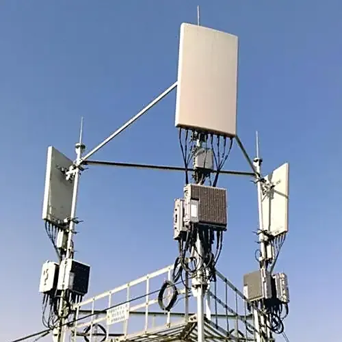
This image shows an application example of N-type connectors in a real-world outdoor environment (e.g., base station, antenna mast). It highlights the role of the N-type connector as a critical component in the entire outdoor RF link, emphasizing how its 50-ohm precision design, robust metal threads, and stable performance from DC to 11 GHz ensure long-term reliability of the signal chain in harsh weather conditions. The image likely shows the connector properly installed with waterproof sealing measures.
Every outdoor RF link relies on one silent component that rarely gets praise — the connector.
When you’re routing a Wi-Fi 6 access point, a 5 GHz bridge, or a LoRa gateway, it’s the N-type connector that holds the signal chain together. With its 50-ohm precision design, metal threads that can survive hundreds of mating cycles, and steady performance from DC up to 18 GHz, it’s trusted across base stations and test benches.
That said, picking the right N-type isn’t just about the connector itself. It’s about how it fits your coaxial cable, the weather it must handle, and whether it has to link with an SMA port or IP67 bulkhead. In the following sections, we’ll go through how to match variants, crimp them correctly on LMR-400, and keep outdoor runs sealed for the long term — all using verified parameters from TEJTE’s RF product line.
Which N-type variant matches your cable and site conditions?
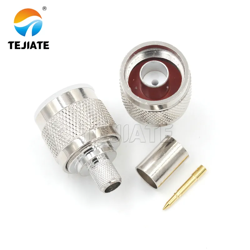
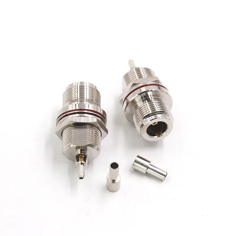
This image is a close-up physical photo of the N-type connector itself, clearly showing its physical structure including the metal shell, threaded coupling mechanism, center pin (typically gold-plated), and PTFE or PEI insulating material. This image is used to illustrate the robust construction and precision interface of the connector body, which is the foundation for its low VSWR (≤ 1.2) from DC to 6 GHz (or even 11 GHz depending on model) and its ability to operate from -45°C to +165°C.
When setting up an RF path, you’ll find that not all N-type connectors behave the same. They come in several mechanical formats — crimp, clamp, compression, and solder — each tuned for specific cable structures and field conditions.
For smaller and flexible cables such as RG316 and RG58, the crimp design is the most practical. The ferrule compression maintains low return loss, and the build process is quick once the strip lengths are correct. RG316, for example, uses a PTFE dielectric and 2.5 mm jacket; it pairs well with N-female clamp connectors like TEJTE N-KFY316-CL, achieving VSWR ≤ 1.2 and stable transmission up to 6 GHz. RG58, at roughly 5 mm in diameter, commonly mates with N-male crimp plugs such as N-JWE58-CR for short outdoor jumpers.
Heavier cables like LMR-200 and LMR-400 benefit from stronger mechanical interfaces. Compression or crimp N-males are rated for DC–11 GHz, while torque values rise from 130 N·cm on LMR-200 to about 180 N·cm on LMR-400. In tower work or long feeder lines, a clamp-type such as N-JH58-CL handles the mechanical stress on 5⁄8″ hardline, supporting torque up to 240 N·cm.
| Cable Family | Connector Type | Attachment | Frequency Range | VSWR ≤ | Torque (N·cm) | Typical Environment |
|---|---|---|---|---|---|---|
| RG316 | N-female bulkhead | Clamp | DC – 6 GHz | 1.2 | 100 – 120 | Indoor / test rigs |
| RG58 | N-male straight | Crimp | DC – 6 GHz | 1.2 | 120 – 150 | Short outdoor runs |
| LMR-200 | N-male right-angle | Compression | DC – 6 GHz | 1.15 | 130 – 150 | Router / antenna links |
| LMR-400 | N-male straight | Crimp | DC – 11 GHz | 1.15 | 160 – 180 | Base-station feeders |
All of these follow TEJTE’s standard build — gold-plated brass pins, nickel-plated shells, PTFE or PEI insulators, and working range –45 °C to +165 °C. Each survives roughly 500 mating cycles without loosening or oxidation.
(Reference parts listed under TEJTE RF Connectors)
How do you crimp an N-type on LMR-400 without hurting return loss?
Crimping an N-type connector onto LMR-400 seems easy until you test it at 5 GHz. The foam-PE dielectric is soft, so over-crimping or uneven stripping can distort impedance and increase VSWR. To get repeatable results, treat it like a precision step rather than routine fieldwork.
Recommended process (based on TEJTE N-JWE400-CR):
- Cut the coax square; clean copper with isopropyl alcohol.
- Slide the ferrule + O-ring before stripping.
- Strip: jacket 8 mm → braid 4 mm → dielectric 3 mm → center 2 mm.
- Crimp the pin with 10.9 mm (0.429″) hex die; pin height should sit within 0 – 0.3 mm.
- Crimp the ferrule fully for 360° braid coverage.
- Tighten the body to 160 – 180 N·cm using a torque wrench.
- Seal with heat-shrink or silicone boot for outdoor use.
When done properly, the joint achieves return loss ≥ 23 dB @ 2.4 GHz and ≥ 20 dB @ 5 GHz, with overall attenuation in line with factory-terminated assemblies.
You can verify this with a quick VSWR check (≤ 1.15). For installers handling multiple cable types, the matching strip data is available under TEJTE’s RF Cable Guide.
Can you install N-type on 5⁄8″ hardline or use screw-on types safely?
The 5⁄8″ hardline used in towers and base stations requires connectors that balance strength and sealing. The correct match is a clamp-type N-male, such as TEJTE N/SMA-KWFK (Part No. 66209). It includes a four-hole flange and silicone gasket that maintain IP67 sealing under torque cycles. The 25 mm square flange spreads mechanical load evenly, and the nickel-plated brass body resists corrosion after years of exposure.
Installation guidance:
- Trim the corrugated sheath carefully; remove any burrs.
- Slide on the O-ring and clamp sleeve.
- Torque to around 220 N·cm, ensuring full thread engagement.
- Apply neutral-cure silicone if the port faces upward or sideways.
“Screw-on” N-types — the quick-fit versions without ferrules — are fine for short bench cables below 1 GHz, but they’re not suited for weathered installs. Their threads don’t seal moisture, and at higher frequencies, the spiral path acts like an inductor, degrading impedance.
For outdoor reliability, stick with crimp or compression N-types using PTFE insulation and gasket sealing. A waterproof model such as N/SMA-KKF (Part No. 40420) withstands –45 °C to +125 °C, 1000 V dielectric pressure, and 500 cycles of mating — exactly what you’d expect from a connector designed for permanent outdoor duty.
(Additional reference: TEJTE N-female waterproof connectors)
Should you use N-type or PL-259/SO-239 for this run?
The question often comes up when building mixed radio systems: should you use an N-type connector or a PL-259/SO-239 pair?
Both are 50-ohm designs on paper, but their structure and sealing tell a very different story once you move above 500 MHz.
The N-type connector is a constant-impedance interface. Its threaded coupling, gold-plated brass center pin, and PTFE dielectric keep the signal path stable well past 6 GHz. Most TEJTE N-series connectors, including the N/SMA-KKF waterproof flange type, are rated DC–6 GHz, VSWR ≤ 1.2, and dielectric withstand 1000 V — perfect for high-frequency or outdoor use.
By contrast, the PL-259 (also known as UHF male) was never meant for modern GHz work. It performs decently up to about 300 MHz, but the geometry lacks controlled impedance. The SO-239 (female) counterpart uses a coarse-thread fit that traps moisture easily. Even with self-amalgamating tape, it rarely reaches IP67 sealing unless paired with external boots.
If your setup runs Wi-Fi 6, 4G/5G, or GNSS signals, use N-type connectors throughout or at least at the antenna ends. For legacy ham or CB rigs under 500 MHz, PL-259/SO-239 may still be acceptable. A simple rule:
High frequency + outdoor = N-type.
Low frequency + indoor = PL-259/SO-239.
(Reference for impedance-controlled designs: see TEJTE’s RF Connector Overview)
Will an SMA radio port connect cleanly to an N-type antenna chain?
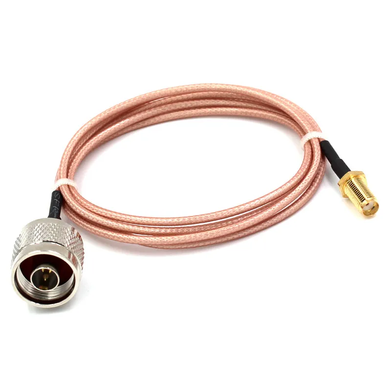
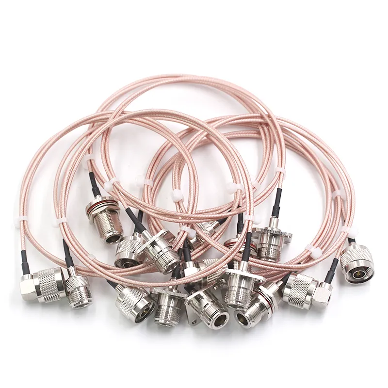
This image shows a typical coaxial jumper, likely with an N-type connector on one end and an SMA connector on the other. This jumper is the standard solution when device ports (e.g., Wi-Fi radios, 4G routers, IoT modems often use SMA) cannot directly mate with antenna ports (often using N-type). Using a single, high-quality 50-ohm jumper (e.g., based on RG316 or LMR-200 cable) avoids the cumulative loss and performance degradation associated with stacking multiple adapters.
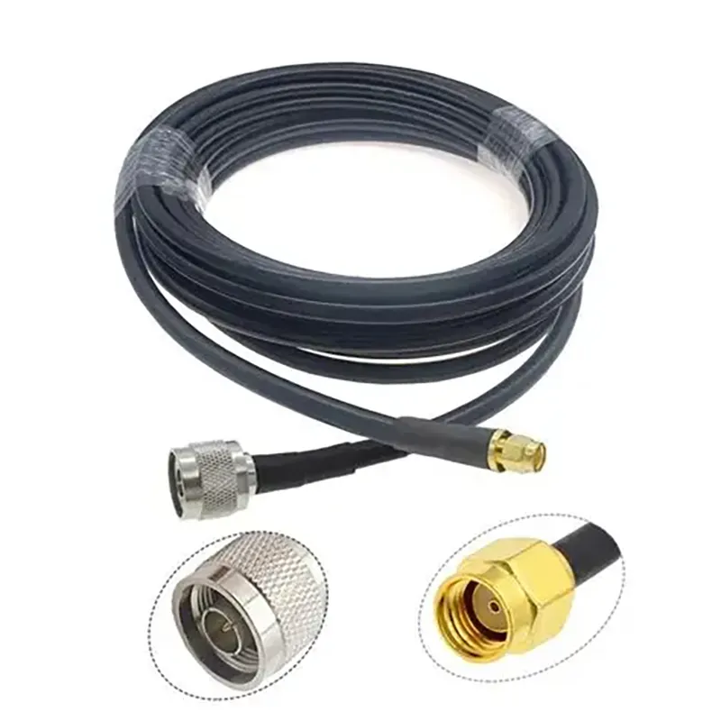
This close-up image shows an N-type to SMA adapter or pre-made pigtail. It provides a direct, low-loss connection method between SMA equipment and N-type antenna systems. The document emphasizes that using a single N-to-SMA jumper (e.g., TEJTE's N/SMA-U, N/SMA-KJ models) maintains lower insertion loss (<0.15 dB @ 6 GHz) and VSWR (≤ 1.2) better than daisy-chaining multiple SMA adapters, which is critical for performance at 5 GHz and above.
Many Wi-Fi radios, 4G routers, and IoT modems expose SMA or RP-SMA connectors on the device side, while antennas use N-type ports. Direct mating isn’t possible — the thread pitch and diameters differ completely — so you’ll need an adapter or pigtail to bridge the two.
The cleanest method is a short coaxial jumper: an SMA-male to N-male or N-female pigtail built with a 50-ohm cable such as RG316 or LMR-200. This approach avoids the stacking loss that comes with using multiple barrel adapters. For instance, a single N to SMA pigtail from TEJTE’s series (e.g., N/SMA-JJ, N/SMA-KJ, or N/SMA-JK) keeps insertion loss below 0.15 dB @ 6 GHz and maintains VSWR ≤ 1.2 : 1.
When you daisy-chain two or more SMA-to-SMA adapters, each interface adds around 0.05–0.1 dB loss and slightly degrades return loss. At 5 GHz, those small reflections can accumulate, creating phase noise or packet drops. That’s why a single N-to-SMA pigtail is the standard practice.
Another detail worth noting: SMA connectors come in two polarities — standard and reverse polarity (RP-SMA). If your access point uses RP-SMA (common on Wi-Fi routers), you’ll need a matching adapter like N/SMA-KKF or a short RP-SMA-to-N jumper.
These are typically assembled using RG316 for short runs or LMR-200 for outdoor durability.
For installation examples and reference cable types, see the SMA to N Adapter Guide, which covers the same coupling geometry discussed here.
How do you achieve IP67 sealing on outdoor N-type bulkheads?
This diagram details the key sealing elements for achieving IP67 rating (dust and temporary immersion protection) during the outdoor installation of an N-type bulkhead connector. It likely shows the dual silicone O-rings (one under the flange, one around the interface thread), the correct torque range (1.2–1.5 N·m), full surface contact between the flange and mounting panel, potential use of a washer (for thin panels), and the application of heat-shrink boots or self-fusing silicone tape. These measures collectively ensure the connector's long-term stability in harsh environments from -45°C to +125°C.
A connector’s electrical performance means nothing if water seeps in. The N-type bulkhead, when installed correctly, can reach IP67 sealing, resisting both rain and temporary immersion. But the sealing depends not only on the connector’s design — it’s also about how you torque and support the assembly.
Most waterproof N-types, such as N/SMA-KKF or N/SMA-KWFK, use dual silicone O-rings—one under the flange and one around the interface thread. The flange version requires full surface contact with the mounting panel. Apply torque between 1.2–1.5 N·m (≈120–150 N·cm) so the O-ring compresses uniformly. If you’re working with a thinner aluminum wall (<1.5 mm), add a flat washer inside to spread the force and prevent distortion.
Other outdoor tips from field installations:
- Create a drip loop so rainwater doesn’t travel directly into the connector.
- Use UV-resistant cable ties to anchor the cable 5–10 cm below the port.
- After thermal cycling, re-torque the connection — PTFE slightly relaxes after a few hot/cold cycles.
- If your system stays under constant sun exposure, a final heat-shrink boot or self-fusing silicone tape extends the seal life dramatically.
TEJTE’s IP67 bulkhead assemblies have been tested from –45 °C to +125 °C, withstanding 1000 V dielectric pressure and maintaining VSWR ≤ 1.2 after 500 cycles. These values align with standard lab practices for outdoor-rated RF enclosures.
More installation notes appear in TEJTE’s RF Cable Loss Guide, which also covers cable length effects on signal attenuation.
Can you verify return loss and prevent early failures after install?
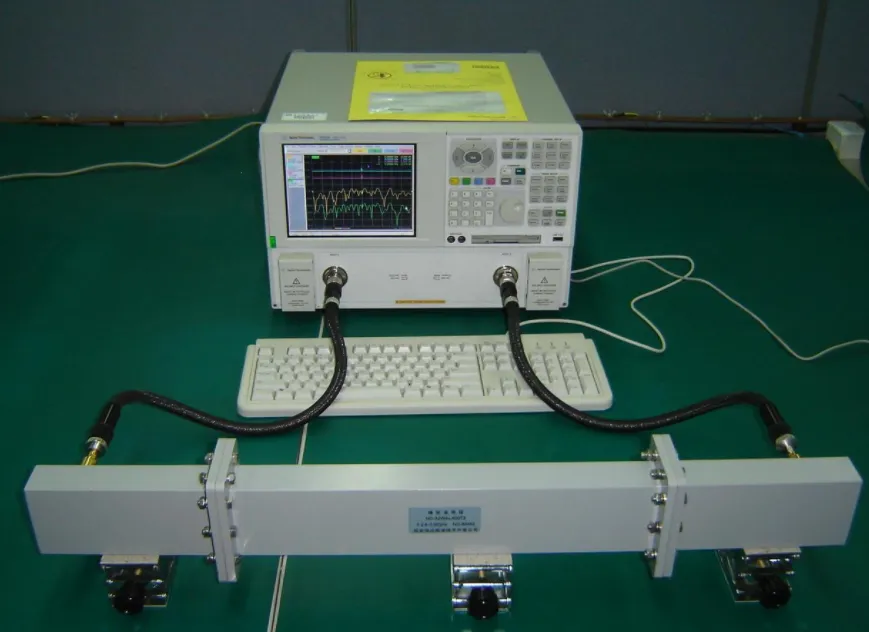
This diagram illustrates the important step of electrical performance verification after N-type connector installation. The image likely shows how to use a handheld VSWR meter or a mini Vector Network Analyzer (VNA) to set the reference plane at the radio port and measure the Voltage Standing Wave Ratio (VSWR) of the entire antenna chain. The goal is to ensure VSWR ≤ 1.2 across the operating band, confirming a good impedance match from the 50-ohm coaxial cable to the N-type interface. This process helps identify potential failures early, such as those caused by improper installation (e.g., over-crimping, missing O-rings).
Once the connectors are mounted and the system looks perfect, there’s still one thing that decides whether it stays that way: return loss. A perfect N-type termination should show a reflection below –23 dB at 2.4 GHz and at least –20 dB at 5 GHz. If the reading drifts upward after installation, moisture or a partial short inside the ferrule is usually to blame.
For quick field validation, a handheld VSWR meter or a mini-VNA can be used. Set the reference plane at the radio port and measure the full antenna chain. A reading of VSWR ≤ 1.2 : 1 across the band confirms that the impedance match from the 50 ohm coax cable to the N-type interface is intact. If you see a rising ripple, check for an over-tightened ferrule or a missing O-ring on the bulkhead.
Before final sealing, engineers often perform a simple continuity test:
- Inner to inner conductor: 0 Ω (no loss)
- Outer to outer: 0 Ω
- Inner to outer: open circuit (> 10 MΩ)
Once verified, apply the final torque and heat-shrink boot. TEJTE’s N/SMA-KKF and N/SMA-KWFK units, both rated for 500 mating cycles, show no measurable degradation even after multiple connect-disconnect sessions under –40 °C to +125 °C.
For recurring maintenance, re-check the return loss after the first thermal season; a 0.1 dB drift is normal, but anything higher may indicate trapped condensation or braid fatigue.
Order once without rework — which N-type SKU fits your cable and site?
| Cable Family | Connector Body / Ends | Attachment Type | Strip Lengths (mm) | Hex Size (mm) | Torque Range (N·cm) | Seal Kit | Suggested TEJTE P/N |
|---|---|---|---|---|---|---|---|
| RG316 | N-female bulkhead straight | Clamp | 5 / 2.5 / 1.5 / 1.0 | 8.0 | 100 – 120 | O-ring + Boot | N-KFY316-CL |
| RG58 | N-male straight | Crimp | 6 / 3 / 2 / 1.5 | 8.9 | 110 – 130 | O-ring + Shrink | N-JWE58-CR |
| LMR-200 | N-male right-angle | Compression | 7 / 3 / 2 / 1.5 | 10.2 | 130 – 150 | O-ring + Shrink | N-JWW200-CP |
| LMR-400 | N-male straight | Crimp | 8 / 4 / 3 / 2 | 10.9 | 160 – 180 | O-ring + Boot | N-JWE400-CR |
All models use nickel-plated brass shells, gold-plated contacts, PTFE insulation, and are qualified to –45 °C ~ +165 °C, dielectric 1000 V, VSWR ≤ 1.2.
When choosing between straight and right-angle forms, remember that every 90° elbow adds about 0.05 dB insertion loss at 6 GHz — small but noticeable in long feeder chains.
For integrators maintaining mixed SMA to N networks, TEJTE’s documentation under RF Connectors Guide cross-references SMA, BNC, and TNC series with equivalent torque and plating data, ensuring consistent specification across product families.
Do you need a step-by-step checklist to crimp N-type on LMR-400?
Tools Required
- Precision cable stripper (LMR-400 gauge)
- Hex crimp tool (10.9 mm die)
- Torque wrench (13 mm head)
- Isopropyl alcohol + lint-free wipes
- Silicone boot / heat-shrink sleeve
Assembly Steps
- Cut cable square; clean debris with alcohol.
- Slide ferrule and O-ring onto the jacket before stripping.
- Strip to lengths — jacket 8 mm / braid 4 mm / dielectric 3 mm / center 2 mm.
- Flare the braid evenly; insert pin until it seats.
- Crimp the pin using the 10.9 mm die.
- Crimp outer ferrule 360° for uniform grip.
- Apply 160 – 180 N·cm torque to the body thread.
- Seal with boot or heat-shrink.
Acceptance Criteria
This close-up image shows a finished N-type connector successfully crimped onto a coaxial cable (context suggests likely LMR-400). It visually demonstrates key acceptance criteria: the center pin is at the correct height and undamaged, the outer braid is fully and uniformly covered by the crimp ferrule, and the connector body is properly seated. Such correct assembly ensures mechanical strength (pull strength ≥ 80 N) and excellent RF performance (return loss ≥ 23 dB @ 2.4 GHz), making it suitable for demanding outdoor applications like base station feeders.
- Pin height: 0 – 0.3 mm above dielectric
- Braid coverage: 100 % around ferrule
- Pull strength: ≥ 80 N
- Return loss: ≥ 23 dB @ 2.4 GHz; ≥ 20 dB @ 5 GHz
- Visual check: no bent pin, no exposed braid
If all checks pass, the connector is ready for service. Rework is discouraged once the ferrule is crimped, as micro-fractures can propagate under vibration. For high-volume production, it’s common to spot-test one unit per batch for VSWR and continuity before field deployment.
You can find additional installation illustrations and torque examples under TEJTE’s SMA Connector Guide, which follows the same assembly philosophy used for precision N-types.
Frequently Asked Questions
1. What crimp hex sizes and strip lengths do I need for an N-type on LMR-400?
For standard LMR-400 coax, the most reliable configuration uses an N-male crimp connector such as TEJTE N-JWE400-CR. The ferrule size is 10.9 mm (0.429″) across flats, and the recommended strip sequence is 8 mm jacket → 4 mm braid → 3 mm dielectric → 2 mm center conductor.
Crimping torque should fall between 160–180 N·cm, enough to secure the braid without collapsing the dielectric.
A quick post-crimp check: make sure the pin height sits 0–0.3 mm above the PTFE. This ensures proper contact pressure and minimal return loss (≥23 dB @ 2.4 GHz). Over-crimping tends to raise VSWR, so always use a torque wrench and verify with a simple reflection test if possible.
2. Are screw-on N-type connectors reliable outdoors, or should I stick to crimp/compression?
Screw-on connectors were created for convenience, not for longevity. While they’re fine for bench testing or short indoor RF links below 1 GHz, they fail quickly in moisture and temperature cycles. The thread path provides no sealing surface; capillary water action can reach the dielectric, detuning impedance.
Crimp and compression N-types, by contrast, include O-ring grooves and heat-shrink boots, achieving IP67 waterproofing when assembled correctly. TEJTE’s N/SMA-KKF series, for instance, uses dual silicone seals and is rated –45 °C to +125 °C, 1000 V dielectric strength, and 500 mating cycles. For any outdoor antenna, crimped or compression-style connectors are the only reliable choice.
3. Can I mate an SMA radio to an N-type antenna without hurting return loss — adapter or pigtail?
Direct connection isn’t possible: the SMA connector has a smaller thread and different pitch. The proper method is a coaxial pigtail — for example, SMA-male to N-male or SMA-male to N-female — built with a flexible 50 ohm coax cable like RG316 or LMR-200.
Each adapter interface adds roughly 0.05–0.1 dB insertion loss. Stacking multiple adapters may double that figure and degrade return loss above 5 GHz. A single N to SMA pigtail solves this, keeping the match below 1.2 : 1 VSWR.
In Wi-Fi or cellular routers, where SMA or RP-SMA connectors are common, this short jumper maintains both mechanical reliability and low signal reflection, even in MIMO configurations.
4. When should I choose N-type over PL-259/SO-239 for ham or Wi-Fi installs?
It depends entirely on frequency and exposure. The N-type connector is a constant 50 Ω design with precise dielectric spacing; it remains stable through 6–11 GHz depending on model. PL-259 (UHF) connectors, though rugged, are impedance-variable and effectively limited to 300–400 MHz.
If you’re running Wi-Fi 6, 4G/5G, or any link over 1 GHz, always choose the N-type. It not only maintains better VSWR but also integrates sealing hardware for outdoor towers. PL-259/SO-239 remains fine for low-frequency amateur setups and CB radios, but mixing the two interfaces in one signal chain often introduces impedance bumps.
5. How often can I connect/disconnect an N-type before wear becomes a problem?
A properly plated N-type connector—nickel body, gold pin, PTFE insulator—handles at least 500 mating cycles before any noticeable degradation. Lightly lubricating the thread with dielectric grease slows oxidation and eases torque friction.
Avoid overtightening: 1.2 N·m (≈120 N·cm) is enough for most mated pairs. Beyond 800–1000 cycles, the female spring fingers may start loosening, slightly raising contact resistance.
In environments where connectors are frequently swapped—like RF test benches—it’s better to use adapters as sacrificial wear points instead of stressing the device’s native port.
6. Which seal parts actually make an N-bulkhead IP67 on a thin aluminum panel?
A proper IP67 connector seal comes from multiple layers working together:
- Front O-ring between the flange and panel surface, compressed evenly.
- Threaded interface O-ring between N-male and N-female couplers.
- Rear heat-shrink boot or silicone sleeve on the cable jacket.
- Optional silicone gasket washer if the panel is under 1.5 mm thick.
In TEJTE’s waterproof designs, like the N/SMA-KWFK four-hole flange connector, both O-rings are pre-installed. When tightened to 1.5 N·m, they compress just enough to block water without deforming the metal. After installation, a quick immersion test confirms whether the joint meets IP67 (1 m depth, 30 min).
7. Can I reuse an N-type connector after de-termination, and what checks are required?
Reusing connectors saves cost but demands careful inspection. After removing a crimped N-type, check for:
- Ferrule deformation — if the crimp barrel is oval or cracked, discard it.
- Center pin looseness — slight wobble can introduce intermittent contact.
- Dielectric burns or discoloration — indicates prior overheating or arc.
- Thread wear — stripped or dull threads compromise sealing torque.
Clamp-style connectors have a better chance of reuse than crimped ones. However, each reinstallation slightly reduces contact pressure and can elevate VSWR. For precision assemblies—especially over 3 GHz—fresh terminations are strongly recommended.
Conclusion
The N-type connector has survived decades of design shifts because it solves three problems at once: mechanical endurance, consistent impedance, and weather resistance. Whether you’re crimping it on a LMR-400 feeder, sealing a bulkhead at IP67, or bridging an SMA-to-N link on a 5 GHz access point, the physics stay the same — stable geometry equals predictable signal.
Every detail matters: strip length, torque, ferrule grip, even the way the O-ring seats under compression. These small tolerances are why TEJTE’s RF assembly line verifies each connector batch to ±0.05 mm strip accuracy and ≤ 1.2 VSWR consistency.
For engineers and installers working with 50 ohm coaxial systems, understanding these fundamentals ensures your next build won’t just work — it’ll stay working through wind, water, and time.
Bonfon Office Building, Longgang District, Shenzhen City, Guangdong Province, China

A China-based OEM/ODM RF communications supplier
Table of Contents
Owning your OEM/ODM/Private Label for Electronic Devices andComponents is now easier than ever.
