SMA attenuator: practical dB, power & VSWR guide
Oct 12,2025
Preface
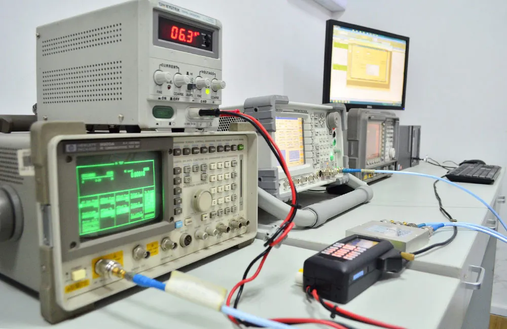
The image introduces how SMA attenuators protect receivers and analyzers by reducing excessive RF power, acting as safety buffers in test and transmission setups.
In RF work, SMA attenuators often play the role of unsung heroes. They don’t generate power, amplify gain, or filter signals, yet they quietly decide whether a system runs smoothly or falls apart under distortion. A mismatched transmitter can overload a receiver in seconds, and anyone who has blown a spectrum analyzer input knows how costly that mistake can be. That’s when a small device like an RF attenuator proves its worth.
At TEJTE, we frequently hear engineers debating a simple but important choice: should they stick with a 2 W fixed pad rated for DC–6 GHz, or invest in a 5 W step attenuator with a 0–130 dB range in 1 dB increments? The answer is never one-size-fits-all. It usually comes down to three practical factors—attenuation level, power handling, and return loss.
Quick tip from the field: keep one or two spare pads in your kit. More than a few engineers have been saved during field testing by a last-minute 10 dB SMA pad that kept a receiver from clipping. Think of an RF attenuator as a seatbelt—most of the time you won’t notice it, but when things go wrong, you’ll be glad it’s there.
Will a 1 W, 2 W, or 5 W SMA attenuator handle your power safely?
CW vs. burst/PEP power and heat rise considerations
Attenuators are rated for continuous-wave (CW) power, usually at 25 °C. For example, a 2 W SMA attenuator can safely dissipate +33 dBm without breaking a sweat in a room-temperature lab. But bursts complicate the story. A short 5 W peak envelope power (PEP) pulse may seem harmless, yet repeated bursts can heat the body and shift performance. That’s why RF engineers testing radar pulses or LTE uplinks often upgrade to 5 W pads, even if average power seems lower.
A quick reminder from the field: if your test gear feels warm to the touch, it’s already too hot. Many seasoned engineers keep a small infrared thermometer handy—cheap insurance against hidden heat build-up.
Derate for temperature and duty cycle to avoid failure
The fine print in datasheets matters. A 2 W attenuator is rated at 25 °C, but in a hot enclosure running at +70 °C, the safe continuous rating may drop closer to 1 W. TEJTE’s fixed SMA attenuators specify a wide range (–55 °C to +125 °C), but even then, derating applies. Step attenuators are a bit more delicate, usually rated for –10 °C to +50 °C in operation, reflecting the mechanical switch inside.
A conservative rule of thumb: run attenuators at no more than 70% of their rated power for continuous duty. Feeding +30 dBm into a 1 W device is asking for trouble; using a 2 W pad makes it safe. And if your transmitter edges toward +37 dBm, it’s time to move into the 5 W class.
Avoid the common trap: antenna labeling vs device labeling mismatch
Datasheets and product boxes don’t always tell the full truth. Outdoor antennas, for example, are usually equipped with an N female port, but some suppliers just label them “N-type.” When your indoor device carries an SMA male jack, the actual adapter you need is an N male to SMA female.
That’s where TEJTE’s N/SMA-K flange adapter (Part No. 08764) comes in. Built with brass and designed for 500 mating cycles, it’s a reliable choice for bridging antennas and routers.
Should you choose a fixed pad, a step attenuator, or a variable SMA attenuator?
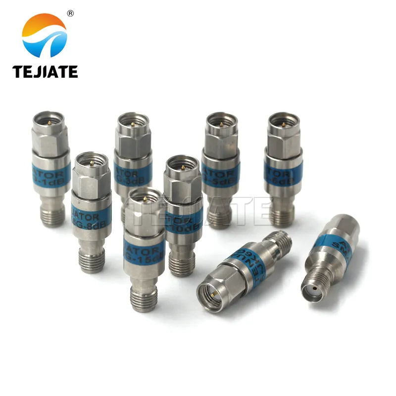
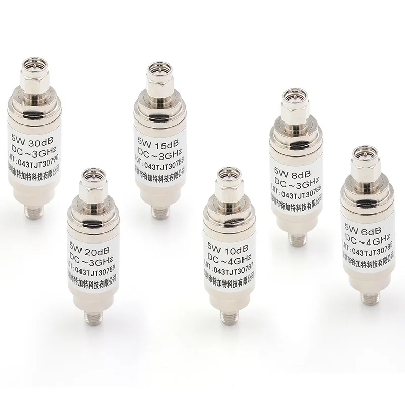
The image shows fixed SMA attenuators used for inline level control. Each pad offers stable attenuation (6–30 dB) and low VSWR ≤1.22, suitable for Wi-Fi, LTE, and IoT testing.
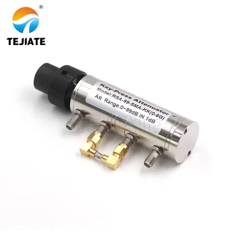
Field swaps vs. bench testing: pick by repeatability and wear
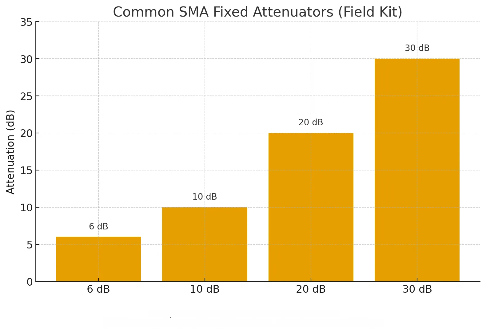
The table lists TEJTE’s SMA attenuator options, covering 1 dB, 3 dB, 6 dB, 10 dB, 20 dB, and 40 dB levels. Each model provides a consistent 50 Ω impedance, VSWR ≤1.22, and frequency coverage up to 6 GHz.
Fixed pads are the simplest and most durable option. A 2 W, 20 dB DC–6 GHz SMA attenuator will deliver the same result every single time you connect it. Many field engineers carry a small kit of 6 dB, 10 dB, 20 dB, and 30 dB pads, ready to plug in when a receiver starts to clip. They’re compact, low-cost, and virtually maintenance-free.
Step attenuators, by contrast, shine on the bench. A TEJTE SMA/N-type step attenuator covering 0–90 dB or 0–130 dB in 1 dB steps allows you to dial in precise values without juggling multiple pads. For R&D labs or device characterization, this saves time and improves repeatability. The trade-off is mechanical wear. Each click-stop is a moving contact, and after thousands of cycles, drift or contact noise may appear.
A practical tip: if you adjust levels multiple times a day, use a step attenuator. If you set it once and leave it in line for weeks, a fixed pad is better.
Click-stop accuracy, resolution (1/2/3 dB steps), and drift
Accuracy comes down to resolution. TEJTE’s step attenuators provide 1 dB resolution across the full range. That’s invaluable when you need to shave off just 2 or 3 dB. Still, tolerances matter. For example, specifications often show ±0.9 dB at 0–8 dB and up to ±2 dB at 10–20 dB. In critical measurements, a fresh fixed SMA attenuator may be more reliable than an aging step unit.
Variable attenuators—either screw-driven or electronic—sit between the two. They’re less common in everyday RF benches but prove useful in automated setups where continuous adjustment is required. If you need flexibility without constant connector wear, a step attenuator usually strikes the best balance.
How do you install a male-SMA to female-SMA pad without damaging connectors?
Wrench sizes, torque order, and strain relief on semi-rigid vs RG-316
SMA connectors are designed for 8 in-lb (≈0.9 N·m) of torque. Too loose, and you risk intermittent contact. Too tight, and you wear out the threads prematurely. Always use a proper SMA torque wrench, not your fingers. For semi-rigid assemblies, strain relief is essential so that the SMA pad isn’t bearing side stress. With flexible coax like RG316 cables, route the cable in gentle curves instead of sharp bends to protect the joint.
TEJTE’s 2 W SMA attenuators are compact—around 30 mm long with brass/nickel bodies—which makes them easy to handle. Still, good practice is to hold the analyzer port steady, rotate the attenuator nut, and apply final torque gently. This avoids twisting the mating port.
Acceptance checks: contact resistance, wobble, and re-torque intervals
Even when installed correctly, connections loosen slightly over time. A quick acceptance check is simple: wiggle the attenuator gently. It should feel firm, without wobble. Rising resistance in measurements can be a sign of dirty contacts—clean them and re-torque. In labs where gear is connected and disconnected hundreds of times, many engineers set re-torque intervals (say every 500 insertions) to maintain accuracy.
A real-world case proves the point: one customer used a 20 dB SMA pad daily on an analyzer input. After a year, the port threads wore down from constant swaps. Switching to a step attenuator for daily bench work reduced the wear and saved the analyzer from costly repairs.
Will this attenuator survive your frequency range (DC–6 GHz / 18 GHz)?
Flatness across band and where datasheets hide the caveats
A DC–6 GHz SMA attenuator is more than enough for Wi-Fi, LTE, and IoT testing. Within this range, TEJTE’s fixed pads stay flat within ±0.5 dB, so you know your 20 dB pad is really 20 dB across the band. But once you move into satellite or radar work—up near 18 GHz—things change. Attenuation can drift, insertion loss creeps up, and those tiny shifts may distort sensitive measurements. That’s why engineers stepping beyond 6 GHz usually switch to DC–18 GHz rated RF attenuators, which guarantee stability across the wider band.
Field note: always check the “attenuation flatness” line in the datasheet. It’s easy to skip, but it tells you if a 30 dB pad is still close to 30 at the band edge—or if it quietly turned into 32.
Instrument ports vs. outdoor nodes: sealing and handling
Lab setups stay clean and cool, but outdoor deployments test hardware differently. A nickel-plated brass pad works fine on the bench, yet an outdoor node benefits from stainless or gold-plated housings that resist corrosion.
Temperature is another silent killer. TEJTE’s fixed SMA attenuators survive –55 °C to +125 °C, but step attenuators are narrower, usually –10 °C to +50 °C, because of their mechanical switches. If you’re mounting gear in rooftop enclosures, those limits may matter more than whether you picked 10 dB or 20 dB.
The takeaway: match not just the dB and wattage, but the frequency and environment. A well-chosen RF attenuator keeps your system stable and your measurements honest.
Order in one pass: which SKU matches your dB, power, and band?
SMA Attenuator Spec-to-Order Matrix
| Target Attenuation (dB) | Frequency Range | Power Rating | Return Loss / VSWR | Connector Gender | Body Finish / Material | Use Case | Suggested TEJTE P/N |
|---|---|---|---|---|---|---|---|
| 1/2/3 dB | DC-6 GHz | 2 W | ≥20 dB RL / ≤1.22 | SMA-M to SMA-F | Brass, nickel | Fine trimming, calibration | 64270 / 64271 / 64272 |
| 5 / 10 dB | DC-6 GHz | 2 W | ≥20 dB RL / ≤1.22 | SMA-M to SMA-F | Brass, nickel | Inline protection, level setting | 64273 / 64274 |
| 20 dB | DC-6 GHz | 2 W | ≥20 dB RL / ≤1.22 | SMA-M to SMA-F | Brass, nickel | Analyzer protection | 64275 |
| 30 dB | DC-6 GHz | 2 W | ≥20 dB RL / ≤1.22 | SMA-M to SMA-F | Stainless | High isolation, strong transmitters | 64276 |
| 0-90 dB (1 dB steps) | DC-3 GHz | 2 W / 5 W | ≥17 dB RL / ≤1.3 | SMA-K to SMA-K / N-K to N-K | Gold, stainless | Bench testing, adjustable chains | KT3-0-90 |
| 0-130 dB (1 dB steps) | DC-3 GHz | 2 W / 5 W | ≥17 dB RL / ≤1.3 | SMA-K to SMA-K | Gold plated | R&D, wide-range margin testing | KT3-0-130 |
Decision prompts:
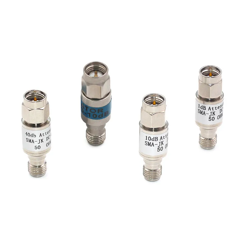
The image shows a 40 dB SMA male-to-female attenuator designed for high-power test ports. It limits RF levels to safe ranges, with insertion loss accuracy ±0.5 dB and frequency range DC–6 GHz.
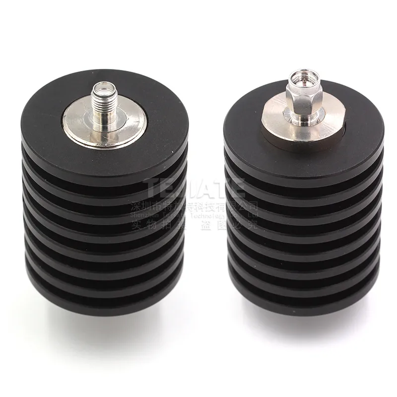
The image presents a TEJTE 5W SMA attenuator, designed for power loads in lab and field use. Built with a stainless-steel body and heat-dissipating core, it maintains low VSWR (≤1.20) under continuous RF stress.
The image showcases TEJTE’s SMA attenuator product family — from compact 1W 6dB models to robust 5W 40dB types — widely applied in RF testing, transmit power control, and network calibration.
- If your transmitter peaks at +33 dBm (2 W) and you need a –10 dB drop, the safe choice is a 2 W, 10 dB fixed attenuator.
- If you’re running continuous +37 dBm (5 W) bursts for testing, a 5 W step attenuator (0–130 dB) gives you both headroom and flexibility.
- For sensitive analyzer inputs handling Wi-Fi or LTE, a 20 dB fixed pad, DC–6 GHz is the standard protection method.
Field note: many labs order a mix—two fixed pads (10 dB, 20 dB) and one step attenuator. That combination covers 90% of test cases without overloading your budget.
For more context on how connector formats affect SKU choices, see our SMA to N adapter guide.
Estimate output power and margin before you go live?
Quick dB-to-Power Calculator
- Inputs:
- Input power P_in (W or dBm)
- Attenuation A (dB)
- Outputs:
- P_out (dBm) = P_in (dBm) – A
- P_out (W) = P_in (W) ÷ 10^(A/10)
- Optional:
- Return loss RL(dB) = –20·log10|Γ|
- VSWR = (1+|Γ|)/(1–|Γ|)
Example 1
Transmitter: +30 dBm (1 W)
Attenuator: 20 dB fixed pad
Output: +10 dBm (10 mW) — safe for most analyzers.
Example 2
Transmitter: +37 dBm (5 W)
Attenuator: 30 dB fixed pad
Output: +7 dBm (≈5 mW) — well within safe limits.
Quick tip: always round up attenuation rather than down. If you think 12 dB is enough, use a 20 dB pad. That extra cushion helps protect expensive instruments.
This little check is especially useful if you’re stacking devices. Two pads in series—say a 10 dB and a 20 dB SMA attenuator—will give you the right attenuation, but you’ll also add a bit of mismatch. Running the math first prevents surprises.
For more on combining attenuation with cable losses, check our U.FL to SMA pigtail guide. It shows how coax loss and attenuator values add up in real-world setups.
FAQ
1. How do I install a 20 dB male-SMA to female-SMA attenuator without damaging the ports?
Always use a proper SMA torque wrench set to 8 in-lb (≈0.9 N·m). Don’t twist the analyzer port—hold it steady and rotate only the attenuator nut. After the first snug fit, re-torque gently. A simple habit like this prevents thread wear and keeps your SMA pad performing consistently. Seasoned engineers also keep dust caps handy; they protect the threads between uses.
2. How many dB should I choose if my receiver is overloading by ~12 dB?
Round up, not down. In this case, go with a 20 dB SMA attenuator instead of 10 dB. That extra headroom prevents clipping and saves you from borderline performance. It’s better to sacrifice a little signal strength than to risk distorted measurements.
3. Will a 1 W SMA attenuator survive short 2 W peaks, or do I need 2 W/5 W with derating?
A 1 W pad might survive a few peaks, but repeated bursts build up heat. The safer path is a 2 W attenuator, or even a 5 W model if your transmitter sits near +37 dBm. Also remember derating: in hot enclosures or outdoor setups, the effective rating drops, so don’t run attenuators at the edge of their spec.
4. What return loss/VSWR is acceptable for a 50 Ω test chain at 2.4/5 GHz?
For lab work, aim for ≥20 dB return loss (≤1.22 VSWR). That ensures reflections stay minimal, especially in precision Wi-Fi or LTE testing. In field deployments, ≥17 dB RL (≤1.3) is often good enough. A quick check: if your readings look “noisy,” it’s worth swapping in a pad with tighter specs.
5. When should I use a step attenuator instead of swapping fixed pads in the field?
A step attenuator is ideal when you need repeatable adjustments on the bench—say, during R&D or when sweeping power levels. In rugged fieldwork, fixed pads are more durable and easier to replace. Many engineers carry both: pads for fast swaps outdoors, and a step attenuator for controlled testing back in the lab.
6. Does adding multiple attenuators in series help matching, or just add loss?
Mostly just more loss. Two pads rated at VSWR ≤1.25 each will combine into something closer to 1.3–1.35. That’s not a disaster, but it won’t improve matching. Stacking can help isolate a DUT from reflections, but it’s best to keep pad count low and pick a single value close to your target.
7. Can I place an attenuator right at the transmitter to protect a spectrum analyzer?
Yes—and you should. Putting the SMA attenuator at the source absorbs reflections immediately, protecting both your analyzer and the transmitter itself. It’s the same principle as wearing safety goggles: don’t wait until after the accident.
7. Can I place an attenuator right at the transmitter to protect a spectrum analyzer?
Yes—and in fact, that’s the safest approach. Placing an RF attenuator, such as a SMA attenuator pad, directly at the transmitter port ensures that excess power and reflections are absorbed before they ever reach the analyzer. This not only shields your test equipment but also stabilizes the transmitter itself by reducing mismatch stress.
Practical tip: in many labs, engineers keep a 20 dB RF attenuator permanently connected to analyzer inputs as a “sacrificial layer.” It’s far cheaper to replace a pad than to repair a damaged analyzer front end.
Bonfon Office Building, Longgang District, Shenzhen City, Guangdong Province, China

A China-based OEM/ODM RF communications supplier
Table of Contents
Owning your OEM/ODM/Private Label for Electronic Devices andComponents is now easier than ever.
