RP-SMA Connector: Polarity, Gender & Antenna Fit
Oct 9,2025
Identify your connector in 30 seconds: is it RP-SMA or SMA?
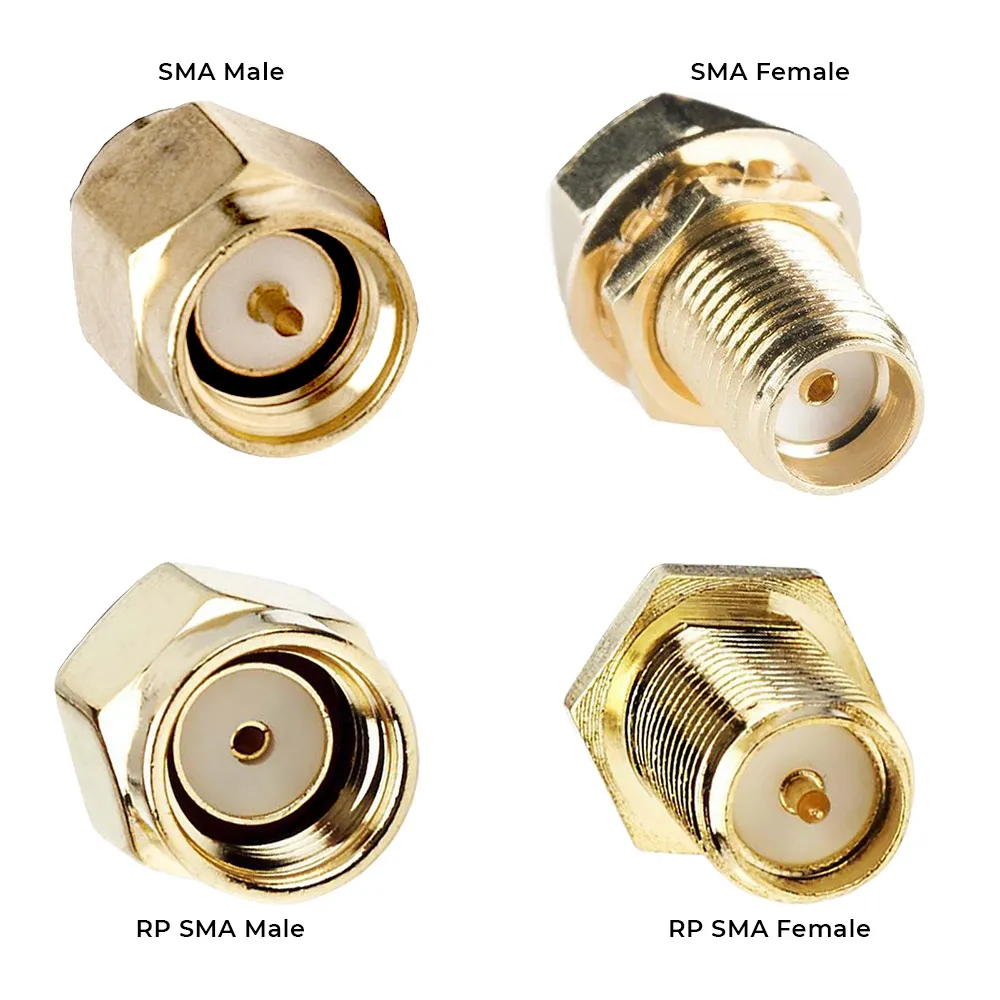
This figure is central to the document, designed to help readers distinguish between standard SMA and Reverse Polarity SMA within 30 seconds. It clearly illustrates the four key types (SMA Male/Female, RP-SMA Male/Female) and highlights whether the center conductor is a pin or socket – the most critical factor for identifying polarity and preventing connection failures due to confusion.
Visual cues: inner pin vs inner hole, reverse-polarity traps
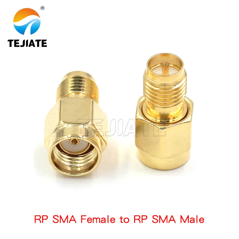
This figure illustrates the internal workings of a reverse polarity connector by showing a mated RP-SMA pair. It helps readers understand that despite identical external threads, the internal "socket-pin" contact is crucial for signal continuity, visually explaining why standard SMA and RP-SMA are incompatible.
Here’s the fastest way to check. In a standard SMA male, you’ll see a small center pin sticking out. In contrast, an RP-SMA male uses the same external thread but hides a socket (hole) inside. That’s the entire reverse polarity SMA trick — the threads remain unchanged, but the gender of the inner conductor is swapped.
Many people only realize this mismatch after they’ve screwed an antenna on tightly and still get no signal. I’ve been there myself, tightening until my fingers hurt, only to discover the problem wasn’t torque but polarity.
Take TEJTE’s RPSMA-JK adapter as a good reference. It features an external thread with an inner pin, supports frequencies up to 6 GHz, maintains contact resistance ≤5 mΩ, and survives over 500 mating cycles. On paper, it’s a rugged choice for routers, FPV transmitters, or lab gear. But even the best connector won’t save you if you confuse SMA with RP-SMA at the ordering stage.
Related read: SMA bulkhead connector
Router vs antenna ends: typical gender/polarity patterns in Wi-Fi gear
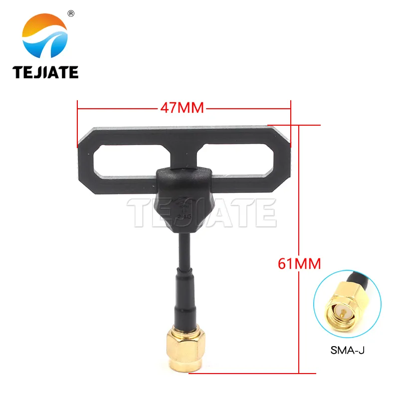
This figure uses a specific model (SMA-J) as an example to show the physical appearance and dimensions of a connector commonly found on Wi-Fi devices. Placed in the context of discussing "typical gender/polarity patterns in router vs. antenna ends," it helps readers recognize connector appearances in real products and understand that conventions can vary among manufacturers.
Most consumer Wi-Fi routers ship with RP-SMA female ports. The antennas that come in the box are RP-SMA male types — a design choice driven by FCC rules intended to stop users from casually upgrading to high-gain antennas.
Not every device follows this convention. FPV drone VTX modules, for example, often use standard SMA, as do certain RF instruments. If you’ve ever tried moving an antenna from a drone to a router and found it wouldn’t seat correctly, now you know why. A quick inspection up front saves you from that “tight but not working” headache later.
Will your Wi-Fi antenna actually fit this RP-SMA connector?
Common router/antenna port mappings (RP-SMA to SMA mistakes to avoid)
| Device Port Type | Antenna Type | Typical Use Case |
|---|---|---|
| RP-SMA Female (router) | RP-SMA Male (antenna) | Consumer Wi-Fi routers (TP-Link, ASUS, Netgear) |
| SMA Female (instrument) | SMA Male (antenna) | RF lab gear, spectrum analyzers |
| RP-SMA Female (FPV module) | RP-SMA Male (antenna) | Drone VTX units, RC transmitters |
| SMA Female (outdoor AP) | SMA Male (antenna) | Outdoor access points, 4G/5G routers |
Mistakes usually happen when someone buys a standard SMA antenna for a router that expects RP-SMA. The threads will grab, the antenna will feel snug, but inside, the pin and socket never meet. The result? Zero RF continuity. This is one of the most common customer complaints I’ve seen, and it always comes down to polarity mismatch.
For a deeper breakdown, see: Wi-Fi antenna connector guide
Quick check: thread size, pin presence, and lock-nut depth
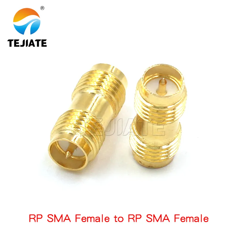
This figure appears when the document introduces the "3-step quick check." It serves as a concrete visual aid to help readers practice the described steps: verifying the universal thread size, observing the center contact (a socket in this female adapter), and noting mechanical features like the lock-nut, enabling reliable connector identification.
If you’re not sure which one you’re holding, run this 3-step check:
- Thread size – Both SMA and RP-SMA use the same 1/4-36UNS thread, so you can’t judge just by screwing them together.
- Pin presence – This is the real giveaway. SMA male has a pin, RP-SMA male has a hole.
- Lock-nut depth – On bulkhead RP-SMA jacks, the nut-and-washer stack is sometimes slightly deeper, which can help you spot the difference in a parts drawer.
It sounds simple, but doing this quick check before installation can save you from the classic “tight but not working” headache.
Choose the right adapter: do you need RP-SMA to SMA or something else?
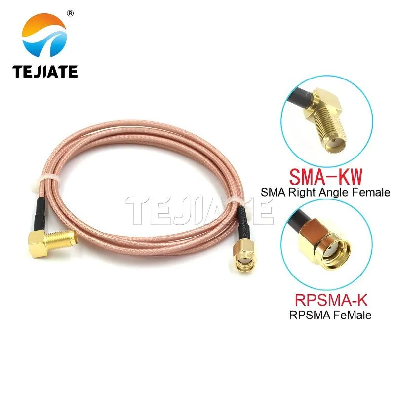
This figure expands the reader's identification skills by showing that the distinction between SMA and RP-SMA also applies to right-angle connectors, not just straight ones. It emphasizes that the principle of polarity checking holds true for different form factors, reminding users to prioritize center contact polarity even when selecting adapters or connectors for space-constrained applications.
Inline vs panel adapters: when to adapt at the chassis vs the cable
The fastest fix is often an inline reverse polarity SMA (RP-SMA) to SMA adapter. It lets you connect mismatched gear in seconds, and TEJTE’s inline couplers, for example, are rated at ≤0.15 dB insertion loss up to 6 GHz. That’s practically invisible for casual Wi-Fi use.
But here’s the catch. Stack two or three adapters directly on your router’s port and you’re asking for trouble. The constant torque on the board-mounted jack can crack solder joints or even lift the connector off the PCB. I’ve seen this happen in the field, and replacing a broken port is far more painful than picking the right adapter in the first place.
When you know you’ll be swapping antennas frequently, a smarter move is to use a short RP-SMA to SMA pigtail or a panel-mounted bulkhead adapter. These options take the mechanical stress away from the device’s connector and make antenna changes far less risky. It’s the difference between worrying every time you twist an antenna on and just swapping it without a second thought.
Loss, mismatch, and durability considerations for frequent swaps
Every extra junction adds a little insertion loss. For high-quality adapters, expect around 0.1–0.3 dB, which may not matter for casual browsing but can hurt in FPV drones or lab test setups where signal margin is tighter.
Another overlooked issue is durability. Gold-plated adapters give great conductivity but wear quickly if you connect/disconnect daily. Nickel plating, while not as flashy, handles repetitive cycles better. That’s why many engineers keep a “sacrificial” adapter attached — the cheap part takes the wear, not the expensive router port.
And don’t forget about cable choice. RG316 coax is a popular option for pigtails because it balances flexibility with low attenuation — only 1.46 dB/m at 2.4 GHz, making it reliable for Wi-Fi frequencies. If space is even tighter, RF1.13 cable works, though at higher loss (around 3.27 dB/m at 2 GHz). In either case, picking the right adapter plus cable length can make the difference between a rock-solid link and a flaky connection.
How do you attach or crimp an RP-SMA connector on coax properly?
Cable prep, crimp hex sizes, and strain relief best practices
Start with the right cable for your project. RG174 is thin and flexible but has higher loss (≈13 dB/100 m at 100 MHz, climbing to 166 dB/100 m at 3 GHz). RG316 offers better performance — only 0.93 dB/m at 1 GHz and still under 1.5 dB/m at 2.4 GHz — making it a favorite for Wi-Fi pigtails. If space is really tight, RF1.13 micro-coax is even smaller at 1.13 mm OD, though you’ll trade some loss (≈3.27 dB/m at 2 GHz).
Once you’ve picked your cable:
- Strip in three layers — outer jacket, braid, dielectric — keeping the conductor clean.
- Fold braid neatly back over the jacket for solid ground contact.
- Insert into connector body until the dielectric is flush.
- Crimp with the right die. Most RP-SMA use a 0.128″ (3.25 mm) hex for the ferrule.
- Add strain relief with heat shrink. This small step prevents cable fatigue when flexed repeatedly.
One little tip from experience: always check your stripper blade sharpness. A dull blade nicks the conductor, and you won’t notice until the cable fails under load.
More details: RP-SMA to SMA cable RG316
Acceptance criteria: pin height, pull test, and contact resistance
After crimping, it’s tempting to assume the job’s done. But a quick inspection saves headaches:
- Pin height — The center pin should be level with the connector face. Too short and it won’t mate; too long and it can damage the jack.
- Pull test — Tug firmly on the cable. A good crimp resists at least 5 N without slipping.
- Contact resistance — Expect ≤5 mΩ for the inner conductor. Anything higher suggests poor crimping or contamination.
Some engineers even do a quick network analyzer sweep after assembly. It might sound overkill, but seeing a VSWR ≤1.3 up to 6 GHz gives peace of mind that your connector is ready for service.
Should you order RP-SMA bulkhead, pigtail, or PCB variants?
Panel thickness vs thread length; nut/washer stack-up
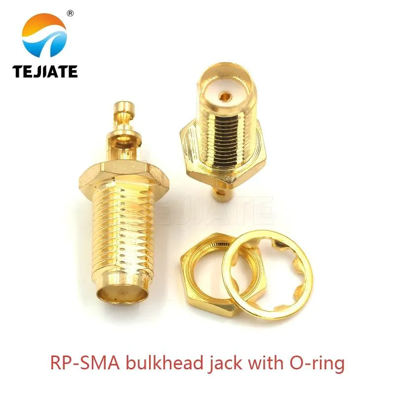
This figure illustrates an RP-SMA bulkhead connector designed for panel mounting, highlighting its integrated O-ring seal. The document context links it to the selection of thread length based on panel thickness and the need for weatherproofing in outdoor applications (like Wi-Fi access points), demonstrating how to choose the right RP-SMA variant for specific use cases.
For chassis-mounted designs, the bulkhead RP-SMA connector is usually the go-to. But here’s the detail many overlook: thread length must match your panel thickness.
- A standard 6 mm thread works fine for thin 1.5–2 mm aluminum panels.
- For thicker housings (3–4 mm), you’ll need a longer-thread version, otherwise the nut won’t bite properly.
At TEJTE, bulkhead jacks like the RP-SMA bulkhead jack with O-ring are designed with adjustable thread options and sealing rings, ensuring both a secure fit and IP-rated weatherproofing. It’s the kind of detail that makes outdoor Wi-Fi access points survive long-term exposure.
One practical tip: always check the washer/nut stack-up height before ordering. I’ve seen engineers forced to file down washers on-site just to make connectors fit — not fun when you’re on a tight deployment schedule.
See product: RP-SMA bulkhead jack with O-ring
PCB jack footprints and reflow-safe vertical SMT options
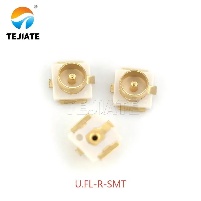
This figure represents a category of compact, surface-mount PCB connector solutions. Referenced in the discussion on "PCB jack footprints and reflow-safe vertical SMT options," it illustrates how miniaturized connectors or adapters like this can be used in space-constrained IoT boards or Wi-Fi modules to interface between onboard miniature connectors and standard RP-SMA ports.
If space is at a premium, PCB-mounted RP-SMA connectors are another option. They come in two main flavors:
- Through-hole PCB jacks — mechanically strong, good for repeated antenna swaps.
- Vertical SMT jacks — compact and reflow-safe, ideal for slim IoT boards or Wi-Fi modules.
For reflow, ensure the insulator material can survive the oven. TEJTE’s RP-SMA PCB connectors use PTFE, which handles the heat without warping. Also, double-check your footprint library — even a 0.2 mm mismatch in pad placement can create impedance discontinuities that wreck your return loss at 5 GHz.
Learn more: SMA PCB connector
If you’re designing a production run, it’s smart to order a few samples and run a test reflow. Nothing beats seeing with your own eyes how the connector behaves under real solder paste and oven conditions.
Can (RP-)SMA bulkhead shells be grounded through the chassis?
Star washer bite, paint/oxide removal, and ground strap tactics
When mounting into a metal enclosure, always use a star washer beneath the securing nut. The sharp edges of the washer dig into the surface, cutting through paint or anodized coatings that would otherwise insulate the shell. Without this bite, your connector might look secure but electrically float, acting like an antenna for noise instead of rejecting it.
Another trick I’ve seen technicians use in the field: scraping away a small ring of paint around the panel cutout before installing the bulkhead. It’s not pretty, but it guarantees metal-to-metal contact. If aesthetics matter, pair the connector with a conductive gasket that handles both sealing and bonding.
And if your housing is plastic? Then the shell has nowhere to ground naturally. In that case, adding a ground strap from the connector body to the system ground is essential. Skipping this step often shows up later as unexpected ESD failures or random Wi-Fi disconnects.
Example: RP-SMA bulkhead jack with O-ring
ESD & EMI tips: bonding priorities in plastic vs metal housings
With metal housings, life is easier. The connector’s body bonds directly to the chassis, and once you ensure good bite through coatings, you’re effectively shielding the device. You’ll see better rejection of both conducted and radiated noise.
With plastic housings, the connector shell can only be bonded if you intentionally add a strap or conductive insert. This step is often skipped in consumer-grade routers, but in higher-spec equipment like outdoor base stations, engineers make it a priority. The reason is simple: without a bonded shell, any static discharge travels straight into the RF front end, risking latch-up or even permanent failure.
One quick rule of thumb I like to use: if the device is going outdoors or into an EMI-heavy environment, always assume shell bonding is mandatory. Indoors and in plastic, you may get away without it — but sooner or later, an ungrounded connector will remind you why it matters.
Where should you buy RP-SMA connectors and how do you avoid fakes?
BOM notes for “RP-SMA vs SMA” correctness in procurement
A common pitfall is sloppy documentation in the Bill of Materials (BOM). Writing just “SMA jack” leaves too much room for error. Instead, every BOM entry should include:
- Polarity — RP-SMA or SMA
- Gender — male (pin) or female (socket)
- Form factor — bulkhead, pigtail, or PCB
- Frequency rating — for example, DC–6 GHz
I’ve seen projects derailed because a team ordered SMA instead of RP-SMA. The parts looked fine until assembly day, when nothing fit. Clear BOM notes avoid that kind of costly headache. For instance, TEJTE’s RPSMA-JK connector is explicitly rated for ≤0.15 dB insertion loss up to 6 GHz and over 500 mating cycles. That level of detail is what purchasing teams need to prevent misorders.
Reference: SMA PCB connector guide
Vendor checklist: plating, dielectric, VSWR, and documentation
A trustworthy supplier should always provide complete technical specs. When you’re evaluating vendors, make sure these boxes are ticked:
- Plating — 3 µm minimum gold over brass, or nickel-plated for durability
- Dielectric — PTFE (Teflon) for low-loss performance up to 6 GHz
- VSWR data — ≤1.2 typical, anything higher signals poor precision
- Datasheet — full drawings, crimp hex sizes, and environmental ratings
Vendors like TEJTE RF connectors publish detailed datasheets and maintain consistency across production batches. That means you’re not gambling on whether the next order will actually fit your coax or PCB footprint.
Order in one pass: which RP-SMA part number matches your use case?
RP-SMA Ordering Matrix
| Use case | Polarity & gender (device to antenna) | Form Factor | Panel thickness to Thread length | Coax type | Attenuation ref. | Crimp hex & pin | Finish & Seal | Suggested TEJTE P/N |
|---|---|---|---|---|---|---|---|---|
| Wi-Fi router to antenna | RP-SMA-F to RP-SMA-M | Bulkhead | 1.5-2.5 mm to ≥6 mm thread | RG174 | 30.16 dB/100 m @ 400 MHz | 0.128" hex, solid pin | Gold, O-ring | TEJTE-RPSMA-BH-174 |
| Drone FPV gear | RP-SMA-F (VTX) to RP-SMA-M (antenna) | Pigtail | N/A | RF1.13 | 3.27 dB/m @ 2 GHz | Split pin | Gold, no seal | TEJTE-RPSMA-PT-113 |
| Outdoor AP | RP-SMA-F to RP-SMA-M | Bulkhead | 3-4 mm to ≥8 mm thread | RG316 | 1.46 dB/m @ 2.4 GHz | 5.41 mm hex | Nickel, O-ring | TEJTE-RPSMA-BH-316 |
| Lab test setup | SMA-F (instrument) to RP-SMA-M | Adapter | N/A | RG58 | 13 dB/100 m @ 100 MHz | 0.255" hex | Gold plated | TEJTE-RPSMA-ADP58 |
Note: Attenuation values are typical at 20–25 °C and sea level, based on TEJTE’s test data for each coax family.
This table isn’t just a catalog — it’s a decision tool. For example, if your project requires ultra-compact routing (like FPV drones), RF1.13 pigtails save space, but you’ll accept higher loss compared to RG316. On the other hand, outdoor APs need bulkhead connectors with O-rings to seal against rain, where nickel plating provides better mechanical wear resistance than gold.
Explore more: RP-SMA to SMA adapter cables
Avoiding daisy-chain adapters and long pigtails to reduce loss
FAQs
What Wi-Fi antenna should I use with an RP-SMA connector?
If your router has an RP-SMA female port, you’ll need an RP-SMA male antenna. That’s the pairing almost all consumer Wi-Fi brands (ASUS, TP-Link, Netgear) use. Swapping in a standard SMA antenna won’t work — the threads fit, but the inner pin and socket don’t touch.
How do I attach or crimp an RP-SMA connector onto RG174/RG316?
Strip the cable in three steps (jacket, braid, dielectric), slide the ferrule on, and crimp with the proper hex die — usually 0.128″ for RG174/RG316 ferrules. Don’t forget strain relief: a small heat-shrink sleeve prevents flex cracks at the connector joint. In lab work, I’ve seen poorly relieved RG174 cables fail after just a few bends. More details are in our SMA crimp connector guide.
What does an RP-SMA connector look like, and which coax types does it support?
An RP-SMA male looks just like an SMA male, but instead of a center pin it has a recessed hole. Supported coax types include RG174 (thin but higher loss), RG316 (better balance of loss and flexibility), and RF1.13 (ultra-compact micro-coax, popular in drones). Each has trade-offs, so check attenuation data before you order.
Is RP-SMA the same as SMA, and how can I tell them apart quickly?
No. The threads are identical, but polarity is reversed. Quick trick: if the male has a pin, it’s SMA; if the male has a hole, it’s RP-SMA. It takes less than 30 seconds to check, and doing so can save you from ordering the wrong antennas.
Can an RP-SMA bulkhead be grounded through the chassis for better EMI?
Yes. In a metal housing, use a star washer so the connector shell bites through paint or oxide. In plastic enclosures, add a ground strap to system ground — otherwise static discharge can go straight into your RF front end. We cover this in depth in our SMA bulkhead connector mounting tips.
Which adapter should I buy for RP-SMA to SMA without adding too much loss?
Skip daisy-chained couplers. A short RP-SMA to SMA pigtail is the better choice, as it keeps insertion loss low (≈0.1–0.3 dB per junction). TEJTE’s RP-SMA to SMA cable RG316 is a common solution because RG316 offers low attenuation and good flexibility.
Where can I buy reliable RP-SMA connectors, and how do I avoid mismatched genders?
Stick with vendors that provide full datasheets, including drawings, VSWR charts, and plating thickness. If those aren’t available, walk away. TEJTE’s RF connectors catalog clearly lists polarity, gender, and frequency rating, so you won’t run into “tight but not working” surprises.
Bonfon Office Building, Longgang District, Shenzhen City, Guangdong Province, China

A China-based OEM/ODM RF communications supplier
Table of Contents
Owning your OEM/ODM/Private Label for Electronic Devices andComponents is now easier than ever.
