
The confusing part is usually the 3 dB.
A buyer orders a small SMA splitter for a lab setup. The unit arrives, the connectors fit, and nothing looks suspicious. Then someone checks the output level and sees roughly half the input power on each branch. The first reaction is often: “Why is the loss so high?”
For a 2-way divider, that result may be completely normal.
A Wilkinson power divider is not selected only because it has the right connector on the outside. The useful questions are more practical: how many branches does the system really need, what frequency range must be covered, how much loss can the link budget accept, and how much isolation is needed between output ports?
If those details are missing from the RFQ, the quoted part may still mate correctly. It just may not be the right RF component.
How many output ports should the RF path actually have?
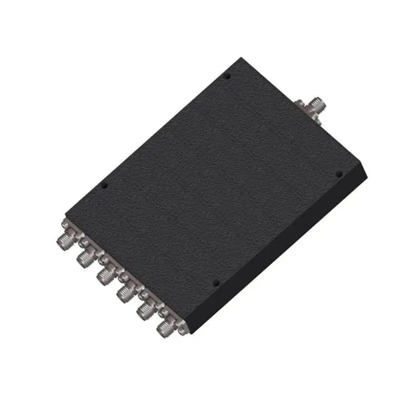
Multi-port Wilkinson power divider in a shielded metal enclosure with SMA interfaces. This type of RF divider is used where equal signal distribution, output isolation, return loss, amplitude balance, and stable multi-channel RF performance are required.
Start with the number of real loads.
One source feeding two receivers is a 2-way requirement. One source feeding four measurement channels is a 4-way requirement. If eight devices must receive the same signal at the same time, then an 8 way RF splitter belongs on the table.
Do not start from the largest SKU that looks convenient.
Extra outputs are not harmless. They bring extra split loss, extra connectors, extra terminations, more cable routing, and more inspection points. In a tight enclosure, even connector spacing can become a problem. A compact SMA power splitter may look fine in a catalog photo, then become difficult to wire once four coax cables are attached side by side.
For an equal power divider, the unavoidable split loss is:
Ideal Split Loss (dB) = 10 × log10(N)
Where:
N = number of equal output ports
| Output Ports | Ideal Split Loss |
| 2 | 3.01 dB |
| 3 | 4.77 dB |
| 4 | 6.02 dB |
| 8 | 9.03 dB |
This is the first number to check before comparing datasheets.
A 2 way power splitter is already about 3.01 dB down at each output. A 4 way power splitter is about 6.02 dB down. An 8-way unit is about 9.03 dB down. That loss is not poor workmanship. It is equal power division.
The cleaner way to think about the measured path is:
Measured source-to-output loss ≈ ideal split loss + excess insertion loss
So if a 2-way RF splitter measures about 3.45 dB from input to one output, the divider has not “wasted” 3.45 dB inside the housing. About 3.01 dB is the theoretical split. The remaining part is excess loss, assuming the test setup and datasheet definition match.
That one distinction prevents a lot of wrong rejections.
Write the RF path before choosing the catalog name
A vague purchasing line might say:
SMA RF splitter, 2 way
That is not enough for a controlled RF purchase.
A better line is:
1 input to 2 equal outputs, 50 ohm, SMA female ports, required frequency range: [x–y GHz].
Now the supplier knows the divider architecture. The inspection team also knows what to verify.
For a 3 way RF splitter, 4 way RF splitter, or coaxial power splitter, add the same information: impedance, port count, connector family, connector gender, frequency range, and whether the split must be equal. If the product will connect to test equipment, also check port spacing and cable clearance. Thick coax can turn a neat drawing into a messy bench setup very quickly.
Unused outputs need attention too.
In a 50-ohm RF system, unused ports normally need matched 50-ohm terminations unless the manufacturer gives a different instruction. Leaving a port open can affect return loss, isolation, and repeatability. The part may still pass a simple visual check. It may even pass continuity. The RF problem appears when the divider is swept, or when one output branch starts interacting with another.
If future expansion is the reason for buying more ports, write that into the decision. Do not let it happen by accident.
Which loss number on the datasheet should you compare?
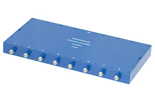
An 8-way RF power divider with multiple SMA ports for distributing one RF source to several channels. An equal 8-way split has approximately 9.03 dB of theoretical split loss before additional excess insertion loss is considered.
Insertion loss is where many power divider comparisons become untidy.
Some datasheets show total source-to-output loss. Some show only excess insertion loss above the theoretical split. Some give typical values. Some give maximum values. Some show one frequency point even though the system needs the whole operating band.
Those are not small wording differences.
| Datasheet Loss Wording | What It May Mean | What to Confirm |
| Total insertion loss | Split loss plus excess loss | Does the number include 3.01 dB, 6.02 dB, etc.? |
| Excess insertion loss | Loss above ideal division | What is the total source-to-output loss? |
| Typical value | Common measured result | Is there a guaranteed maximum? |
| Maximum value | Acceptance limit | Across which frequency range? |
| Single-frequency value | One-point test result | What happens at low and high band edges? |
For link-budget work, calculate the expected output level instead of relying on one label.
Pout(dBm) = Pin – 10log10(N) – ILexcess – ILcable – ILadapter
Example:
Input power: +10 dBm Divider: 2-way equal split Ideal split loss: 3.01 dB Excess insertion loss: 0.50 dB Cable loss after divider: 0.80 dB Adapter loss: 0.20 dB Estimated output level: +5.49 dBm
That final number is what the receiver, analyzer, or downstream module actually sees.
The divider is only one part of the passive path. A sample may work on the bench with a short cable and no adapter stack. Production may use a longer cable, a tighter bend, or one extra adapter on every output. At 2.4 GHz, 5.8 GHz, or microwave frequencies, those small losses stop feeling small.
Keep split loss and excess loss in separate fields
Avoid writing only:
Insertion loss < 3.5 dB
For a 2-way divider, that sentence can be read two ways. It may mean total source-to-output loss below 3.5 dB. Or it may mean excess insertion loss below 3.5 dB on top of the normal 3.01 dB split. Those two requirements are very different.
A clearer RFQ line is:
2-way equal Wilkinson power divider, 50 ohm. Maximum excess insertion loss: [value] dB across [frequency range]. Total source-to-output loss = ideal split loss + excess insertion loss.
This wording gives purchasing, engineering, and incoming inspection the same baseline. It also stops a normal equal-split result from being treated as a bad part.
Why does output isolation matter after the signal has already been divided?
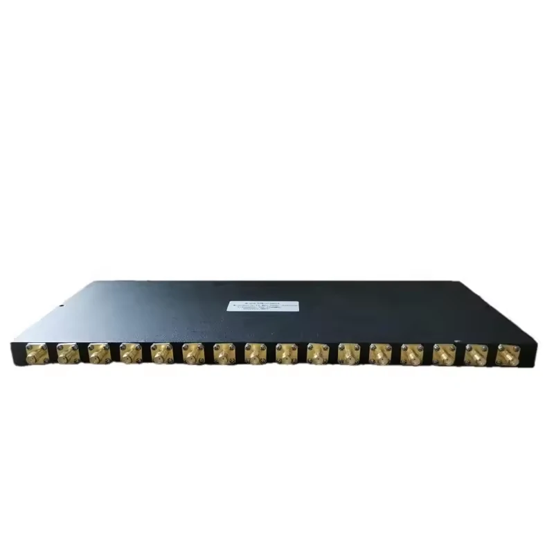
Rack-style multi-way RF power divider designed for distributing an RF signal across multiple output ports. Multi-port dividers require careful evaluation of theoretical split loss, excess insertion loss, isolation, impedance, connector format, and frequency range.
Loss tells you how much signal reaches each output. Isolation tells you how much one output can bother another.
Those are different problems.
In a Wilkinson divider, the isolation resistor is part of the reason the output ports can be separated from each other while still sharing the same input source. That separation becomes useful when the connected loads are not perfectly quiet, perfectly matched, or perfectly identical. Real receivers and instruments rarely behave that neatly.
A simple example: one source feeds two receivers. Receiver A has a slightly poor input match. Receiver B is more sensitive and sits close to its threshold. Without enough output-to-output isolation, reflections or load interaction from one branch can disturb the other branch. The signal was divided correctly, but the branches are no longer behaving independently.
That is why RF splitter isolation should not be treated as a minor datasheet line.
Isolation becomes more important in these layouts:
| Application | Isolation Priority | Why It Matters |
| One source feeding two passive monitors | Medium | Branch interaction may still affect readings |
| Multiple sensitive receivers | High | One receiver path can disturb another |
| GNSS signal distribution | High | Receiver desensitization is a real risk |
| Parallel RF measurement paths | High | Coupling can corrupt comparison data |
| Noncritical signal monitoring | Medium | Depends on load match and frequency |
A multi-receiver GNSS distribution setup is a good practical case. One antenna signal may be divided into several vehicle or module receivers. The designer does not only care that each branch gets signal. They also care that one receiver input does not pull, reflect, or disturb the others. In that kind of system, insertion loss, return loss, amplitude balance, and output isolation should be checked together.
Do not approve a divider by isolation at only one center frequency if the system uses a wider band. The worst point is often near the band edge.
Do not confuse isolation with insertion loss
A divider with acceptable insertion loss can still have weak isolation.
Insertion loss answers this:
How much signal reaches the output?
Isolation answers this:
How much can one output branch interact with another branch?
For a 2-way divider, engineers often look at transmission paths such as S21 and S31, then isolation between output ports such as S23. For a multi-way unit, the same idea expands across more output combinations.
If the divider is used only for rough signal monitoring, the isolation target may not be severe. If it is used for receiver distribution, coherent testing, or calibration work, weak isolation can turn into a hidden measurement problem.
How tight must amplitude and phase balance be?
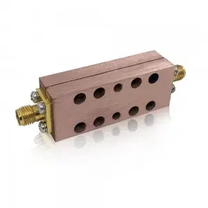
A compact Wilkinson 2-way power divider featuring SMA interfaces for splitting one RF input into two equal outputs. Suitable for RF testing, receiver distribution, laboratory systems, and microwave signal routing where insertion loss and output isolation are important.
Two outputs can both have acceptable loss and still fail as a pair.
That sounds strange until you look at the requirement. In many systems, the absolute signal level matters most. In others, the relationship between channels matters just as much. If output 1 is 0.2 dB different from output 2, a simple monitoring system may not care. A phase-sensitive test setup may care very much.
Amplitude unbalance for a 2-way divider is usually checked by comparing the two transmission paths:
Amplitude Unbalance = |S21 – S31|
For a multi-output RF power divider:
Amplitude Unbalance = maximum output transmission – minimum output transmission
That keeps the comparison focused on path-to-path difference, not only absolute loss.
Phase balance becomes important when the downstream channels must remain coherent. Common examples include phased systems, multi-channel receivers, antenna-array distribution, calibration networks, and IQ measurement paths.
This kind of table is more useful than a vague note saying “balanced outputs.” It gives the inspection team something to record.
For a basic RF signal splitter used to feed two noncritical monitors, a loose balance requirement may be acceptable. For a calibration fixture or multi-channel receiver path, ask for the actual amplitude and phase balance across the full operating band.
Keep balance separate from total loss
Do not mix these two judgments:
Is each path low enough in loss?
and:
Are the paths close enough to each other?
A divider may have similar path loss on both outputs but too much total loss for the system. Another divider may have acceptable total loss but poor path-to-path balance. Both cases are possible.
That is why S-parameter data is useful when the application is sensitive. Visual inspection cannot tell you phase balance. Connector mating cannot confirm amplitude tracking. A part can look clean and still be wrong for coherent RF work.
When is a Wilkinson topology preferable to a resistive splitter?
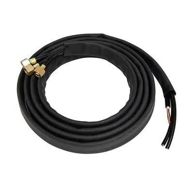
RF coaxial cable assembly for connecting power divider ports to receivers, analyzers, antennas, or other RF equipment. Cable length, attenuation, connector type, and bend routing should be included when calculating total source-to-output signal loss.
A Wilkinson divider is usually attractive when the design needs lower excess loss, good matching, equal in-phase outputs, and useful output isolation within a defined RF band.
That does not mean every splitter should be Wilkinson.
A resistive splitter can make sense when very broad bandwidth, simple construction, or low-frequency behavior matters more than efficiency. In some applications, near-DC coverage is more important than low excess loss. In others, isolation and power efficiency are worth the narrower design constraints of a Wilkinson network.
The topology should follow the job.
| Requirement | Wilkinson Divider | Resistive Splitter |
| Low excess loss | Strong candidate | Usually less attractive |
| Output isolation | Strong when properly designed | Depends on structure |
| Near-DC operation | Often limited by design | Often more suitable |
| Very broad bandwidth ratio | Must verify | Often useful |
| Equal in-phase outputs | Common advantage | Possible, but check data |
| Power efficiency | Better in balanced splitting | More dissipative |
| Simple monitoring use | Often acceptable | Often acceptable |
A procurement mistake is calling every metal RF splitter a Wilkinson power divider. The housing does not prove the internal circuit. If topology matters, ask for it directly.
The RFQ can say:
Wilkinson topology required, 50 ohm, equal split, isolation and S-parameter data required across.
If topology does not matter, write the performance requirements instead:
50 ohm RF power splitter, equal outputs, maximum total loss/excess loss, minimum isolation, return loss, power rating, and connector format specified across.
That gives the supplier room to offer a suitable structure without guessing.
Do not let the product name replace the test data
A part labeled “Wilkinson” still needs frequency, loss, isolation, balance, match, power, and connector checks. A part labeled “RF splitter” may still be perfectly acceptable if it meets those same requirements.
For sourcing, the better habit is to ask:
What does the RF path need to prove?
Not only:
What is the splitter called?
That small shift helps separate useful divider selection from catalog-name matching.
How should frequency range be approved for a real RF system?
Do not approve the divider at one comfortable frequency and assume the rest of the band will behave the same.
A Wilkinson network is built for a defined RF range. Some units are narrowband. Some are broadband. Some connectorized dividers cover several GHz cleanly, but the usable result still depends on the internal circuit, connector launch, housing design, and how the ports are measured.
For a real system, check the full working band:
| Item to Confirm | Why It Matters |
| Lowest operating frequency | Some Wilkinson designs do not extend near DC |
| Highest operating frequency | Loss, return loss, and isolation may worsen at the edge |
| Harmonics or test frequencies | The divider may be used beyond the nominal signal band |
| Future band expansion | Avoid approving a part that has no margin |
| Connector rating | The connector can become the limit even if the circuit is suitable |
The sweep should include input return loss, output return loss, source-to-output transmission, isolation, amplitude balance, and phase balance. Looking only at S21 is too thin for a production decision.
Match power handling to the actual port condition
Power rating is not just a number printed beside the frequency range.
A divider used as a splitter may behave differently from the same device used as a combiner. In balanced Wilkinson splitting, the isolation resistor ideally dissipates little power. Under imbalance, mismatch, or combining conditions, that resistor can see more stress.
So avoid calculating only by dividing watts.
Use dB for the RF path first. Then convert to watts if thermal limits, transmitter limits, or safety margins require it.
A practical power-budget sheet should record:
| Field | Buyer Note |
| Input power | CW or peak power should be clear |
| Frequency | Power rating may depend on band |
| Port count | Determines expected divided output |
| Load condition | Matched or possible mismatch |
| Splitter rating | Do not assume combiner rating is identical |
| Ambient temperature | Enclosure heat may reduce margin |
| Connector type | SMA and N-Type layouts may not share the same power limit |
| Safety margin | Follow project or manufacturer requirement |
Choose the connector and housing from the installation, not the keyword
An SMA power splitter is useful where the RF level, size, and frequency range fit a compact threaded interface. It is common in lab setups, RF modules, wireless equipment, and small distribution networks.
N-Type configurations make more sense when the system needs a larger interface, stronger mechanical handling, or higher practical power margin. TEJTE power divider products include SMA and N-Type configurations such as 1:2, 1:3, 1:4, and 1:8 across different RF bands, but the port format still needs to match the actual installation.
Do not only write “SMA” or “N type.” Write the gender on every port.
Input: SMA female Outputs: SMA female x 2 Impedance: 50 ohm Frequency: [required range] Mounting: bench / panel / enclosure
Connector spacing also matters. Four straight SMA ports may be fine with flexible RG316 jumpers. The same spacing may be annoying with thicker low-loss coax. If the unit will sit in a box, include cable bend radius and service clearance before ordering.
When can a divider also be used as an RF splitter combiner?
A passive divider is often reciprocal, but that does not make every splitting use safe when reversed.
Combining depends on the signals. Equal coherent inputs behave differently from unrelated signals. Inputs with different amplitude, different phase, or different frequencies can push power into the isolation resistor or create unexpected loss and heating.
If several answers are unclear, do not treat the part as a casual RF splitter combiner. That topic deserves its own combiner selection review, especially for multiple transmitters or higher-power systems.
Validate the unit with a VNA before accepting production
For sensitive applications, the acceptance test should match the RFQ.
A simple incoming test sequence can be:
- Measure input return loss.
- Measure each source-to-output path.
- Measure output return loss.
- Measure output-to-output isolation.
- Compare amplitude and phase balance.
- Confirm all unused ports are terminated correctly during measurement.
Keep theoretical split loss out of the excess-loss judgment. A 2-way unit should not fail just because each output is near the 3 dB region. Compare the measured result against:
ideal split loss + allowed excess insertion loss
A compact acceptance table is usually enough:
| Parameter | Test | Acceptance Source |
| Input return loss | S11 | RFQ / datasheet |
| Transmission | S21, S31, etc. | RFQ / datasheet |
| Excess insertion loss | Calculated | RFQ |
| Output return loss | S22, S33, etc. | RFQ / datasheet |
| Isolation | S23, etc. | RFQ / datasheet |
| Amplitude balance | Path comparison | RFQ |
| Phase balance | Path comparison | RFQ |
| Port labeling | Visual check | PO / drawing |
This is also where small ordering mistakes show up: wrong gender, unclear port labels, mixed connector formats, or a divider quoted for a narrower band than the system actually uses.
FAQ
Why does a 2-way Wilkinson power divider lose about 3 dB?
Because equal division sends half the input power to each output. Half power is about 3.01 dB below the input level. That is theoretical split loss, not automatically excess component loss.
Is insertion loss added on top of theoretical split loss?
Sometimes yes, depending on the datasheet wording. Confirm whether the stated value is total source-to-output loss or excess insertion loss above ideal division.
Should unused ports on a 50-ohm RF splitter be terminated?
Normally yes. Unused ports should usually have matched 50-ohm terminations unless the manufacturer states otherwise. Open ports can affect return loss, isolation, and repeatability.
Is a Wilkinson divider always better than a resistive splitter?
No. Wilkinson dividers are useful for low excess loss, good matching, and output isolation within a designed band. Resistive splitters may be better for some very broad or low-frequency requirements.
Can a Wilkinson divider work as a combiner?
Often it can, but combiner use depends on phase, amplitude, frequency relationship, power rating, and isolation-resistor dissipation. Do not assume reverse operation is safe without checking the conditions.
Which VNA measurements matter most?
For a 2-way unit, check S11, S21, S31, output return loss, and output-to-output isolation. Then compare amplitude and phase balance between the two output paths.
What should buyers write in a power divider RFQ?
Write port count, impedance, frequency range, topology if required, insertion-loss definition, isolation, return loss, balance, power handling, connector gender, mounting, and whether S-parameter data is required.
Final Practical Note
A good power divider order is usually won before the quotation stage.
If the RFQ separates ideal split loss from excess insertion loss, defines the full frequency range, lists isolation and balance targets, and names every connector port clearly, the supplier has much less room to guess. That matters more than choosing the nicest-looking splitter photo.
For TEJTE power divider selection, send the port count, operating band, impedance, connector gender, input power, and whether the unit will be used only as a splitter or also as a combiner. Those details are enough to start with the right RF path instead of repairing the wrong one later.
