What Is a 7/16 DIN Connector (L29)? Uses, Torque & Adapters
Aug 27,2025
Introduction
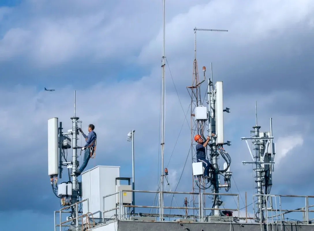
If you’ve ever worked on a rooftop cell site, a distributed antenna system (DAS), or a telecom shelter in the middle of summer heat, chances are you’ve come across a 7/16 DIN connector. Also known as the L29 connector or sometimes just “DIN 7/16,” this threaded coaxial interface has been a workhorse in high-power RF systems for decades.
So, what makes it special? In short: it’s built for power handling, low Passive Intermodulation (PIM), and reliable outdoor performance. When smaller connectors struggle to carry high RF loads or break down under weather stress, the 7/16 DIN steps up. That’s why you’ll still find it widely used on macro base stations, rooftop antennas, broadcast towers, and in-building DAS hubs.
For engineers, technicians, and even procurement teams, knowing the role of this connector isn’t optional—it’s critical. Mis-selecting connectors can introduce signal loss, raise PIM levels, or even damage expensive gear. This guide breaks down the anatomy, specs, torque values, weatherproofing methods, common adapters, and real-world comparison with N-Type and 4.3-10 connectors.
By the end, you’ll have a practical checklist for when to use the 7/16 DIN connector, what tools to keep on-hand, and how to avoid the most common mistakes.
What Is a 7/16 DIN Connector (L29)?
If you’ve ever worked on a rooftop cell site, a distributed antenna system (DAS), or a telecom shelter in the middle of summer heat, chances are you’ve come across a 7/16 DIN connector. Also known as the L29 connector or sometimes just “DIN 7/16,” this threaded coaxial interface has been a workhorse in high-power RF systems for decades.
So, what makes it special? In short: it’s built for power handling, low Passive Intermodulation (PIM), and reliable outdoor performance. When smaller connectors struggle to carry high RF loads or break down under weather stress, the 7/16 DIN steps up. That’s why you’ll still find it widely used on macro base stations, rooftop antennas, broadcast towers, and in-building DAS hubs.
For engineers, technicians, and even procurement teams, knowing the role of this connector isn’t optional—it’s critical. Mis-selecting connectors can introduce signal loss, raise PIM levels, or even damage expensive gear. This guide breaks down the anatomy, specs, torque values, weatherproofing methods, common adapters, and real-world comparison with N-Type and 4.3-10 connectors.
By the end, you’ll have a practical checklist for when to use the 7/16 DIN connector, what tools to keep on-hand, and how to avoid the most common mistakes.
The 7/16 DIN connector is a threaded RF connector developed to meet the needs of cellular and broadcast networks that push both high power and low PIM requirements. The name comes from its metric dimensions: 7 mm outer contact and 16 mm inner insulator diameter.
You’ll often see it labeled in different ways across vendor catalogs:
- L29 connector (its IEC standard code)
- DIN 7/16 (from the German standards body, Deutsches Institut für Normung)
- 7 16 connector or connector din 7 16 (search variants in North America and Asia)
Don’t get confused—these terms all refer to the same connector family.
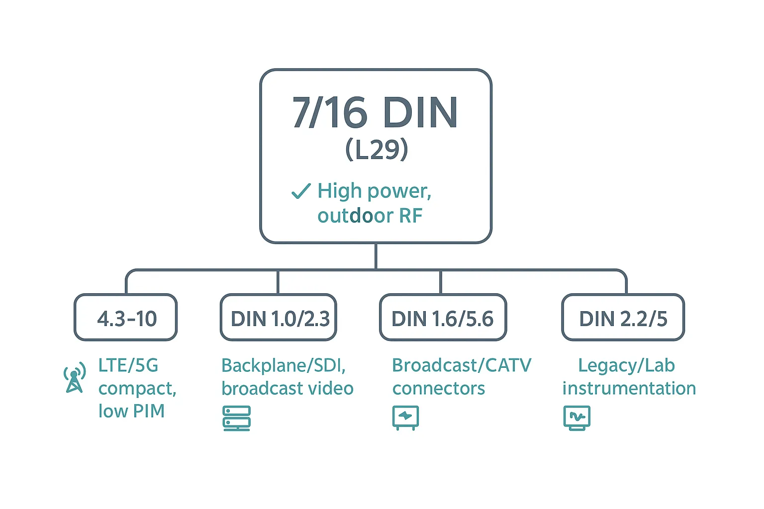
Minimal family-tree infographic showing the DIN coaxial connector family. 7/16 DIN (L29) is centered as a high-power outdoor RF interface, with branches for 4.3-10 (LTE/5G compact, low PIM), DIN 1.0/2
Where It’s Used
- Macro base stations – The classic application, where high transmit power and multiple carriers demand low-PIM connections.
- Rooftop and outdoor antennas – Because of their robust weather sealing and mechanical strength.
- DAS (Distributed Antenna Systems) – Especially in stadiums, arenas, and airports where PIM must be tightly controlled.
- Broadcast links – TV and radio towers often rely on DIN 7/16 for both durability and low loss at high power levels.
Think of the 7/16 DIN as the “big iron” of RF connectors: not the smallest or cheapest, but built to perform reliably under harsh conditions.
Anatomy & Specs of the 7/16 DIN Connector
At first glance, the 7/16 DIN looks chunky compared to something like an SMA or even an N-Type. That’s intentional. Its threaded coupling ensures solid mating under vibration and weather stress, while its size allows for larger contact surfaces, which translates into higher power handling.
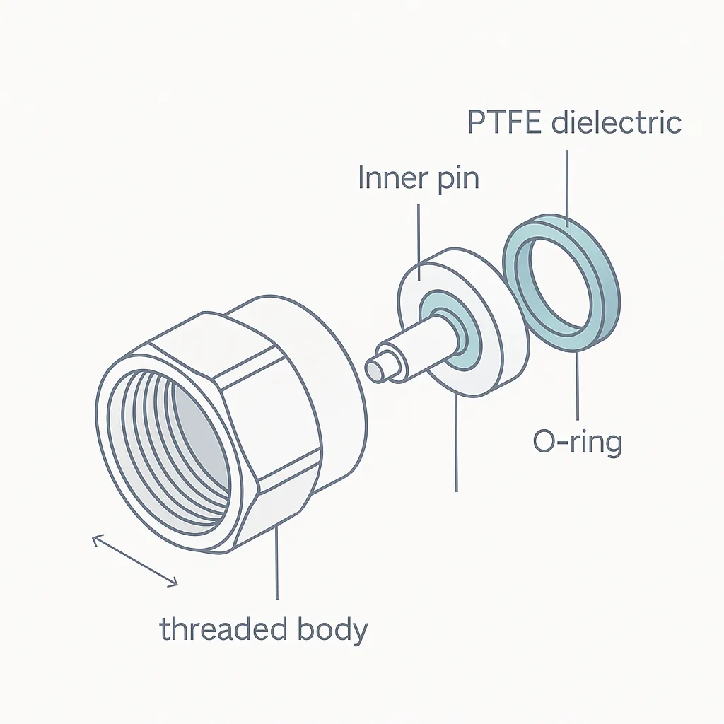
Clean vector diagram labeling the threaded shell, inner pin, PTFE dielectric, and O-ring seals.
Key Features
- Coupling mechanism: Threaded, typically requiring a torque wrench to achieve proper spec.
- Impedance: Standard is 50 Ω, optimized for RF telecom and broadcast applications.
- Frequency range: From DC up to 7.5 GHz, covering VHF, UHF, and many microwave bands used in cellular networks.
- Power handling: Supports hundreds of watts (and in some cases >1 kW), depending on cable type and frequency.
- Materials: Brass or copper alloy bodies, often silver-plated or nickel-plated; PTFE dielectric; rubber O-rings for sealing.
- Durability: Typical mating cycle rating is around 500 connect/disconnect operations, far higher than fragile PCB connectors like U.FL.
Why It Works Outdoors
The connector’s large body and sealing system give it strong resistance to weather. When combined with accessories like weatherproof boots or self-amalgamating tape, 7/16 DIN interfaces can stay operational for years in rain, snow, or coastal salt fog.
Quick Specification Snapshot
| Parameter | Typical Value | Notes |
|---|---|---|
| Impedance | 50 Ω | Standard for telecom RF |
| Frequency Range | DC – 7.5 GHz | Usable across VHF, UHF, microwave |
| Power Handling | >500 W @ 2 GHz | Depends on cable & cooling |
| Return Loss (VSWR) | <1.2 up to 2.5 GHz | Low reflection for efficiency |
| Mating Cycles | ~500 | With proper torque use |
| Weatherproof Rating | IP67–68 | With sealing kits |
Power, PIM & Performance of 7/16 DIN
When engineers talk about the 7/16 DIN connector, three words often come up: power, PIM, and reliability. This connector wasn’t designed for tiny IoT boards or lab instruments—it was engineered for systems where you’re pushing serious wattage into antennas day after day.
Why High Power?
The large contact surfaces of the 7/16 DIN reduce resistance and allow more current to flow without overheating. That’s why you’ll find them on base station feeders and broadcast transmitters where output stages may exceed several hundred watts. Smaller connectors, like N-Type, simply can’t manage this load as safely.
Low Passive Intermodulation (PIM)
PIM is the invisible enemy in multi-carrier systems. Two or more RF signals can interact at a poorly made junction, creating unwanted mixing products that fall back into your operating bands. These artifacts reduce network capacity and degrade coverage. The 7/16 DIN connector’s mechanical stability, silver-plated surfaces, and tight torque control make it one of the lowest-PIM solutions still widely available.
Field engineers know this first-hand: a connector that isn’t torqued properly or has surface contamination can spike PIM measurements instantly. That’s why the 7/16 DIN remains the default for operators who still prioritize ultra-clean RF paths.
Performance Snapshot
| Performance Metric | Typical Value | Application Context |
|---|---|---|
| Power Handling | 500–1500 W (band-dependent) | Base stations, broadcast |
| PIM Rating | -155 dBc or better | Multi-carrier LTE/5G |
| Frequency Range | DC – 7.5 GHz | Cellular, DAS, broadcast |
| VSWR / Return Loss | ≤1.2 up to 2.5 GHz | Stable efficiency |
| Reliability | 500+ mating cycles | With proper torque use |
Torque Values & Tools
Ask any field technician: improper torque is the number one cause of connector failures. Too loose, and you invite moisture ingress or PIM spikes. Too tight, and you risk damaging threads or deforming the dielectric.
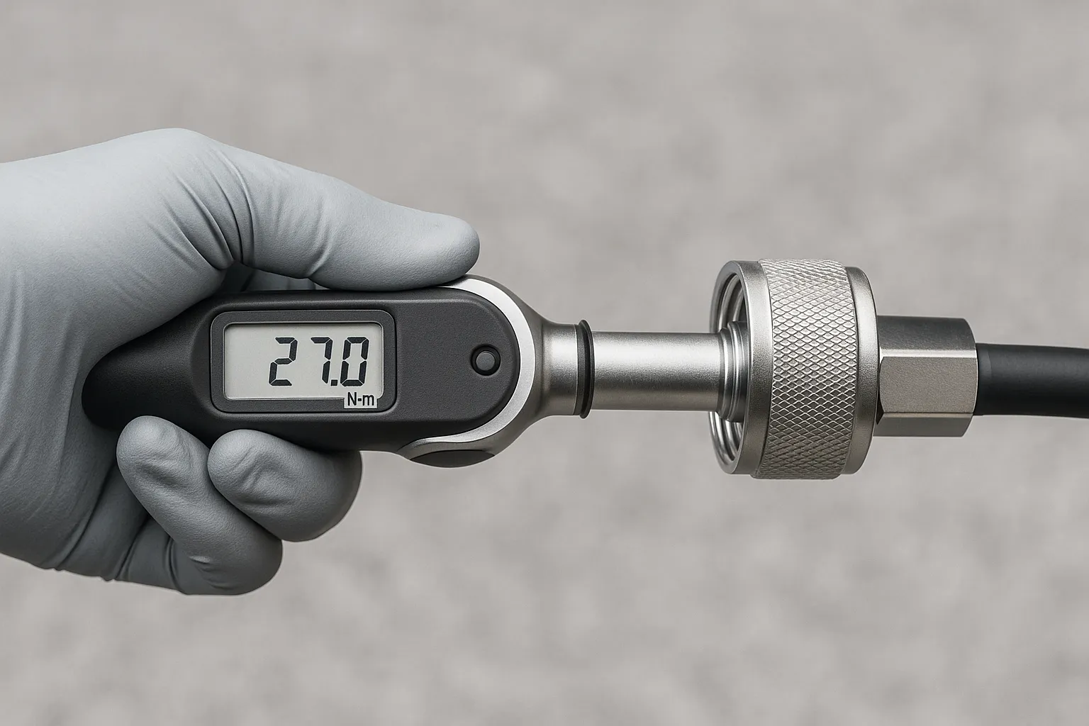
Technician tightening a 7/16 DIN with a torque wrench; neutral background; no visible brands.
Standard Torque Guidelines
Most manufacturers recommend 25–30 N·m (Newton-meters) for 7/16 DIN connectors. Some product variants or adapters may differ slightly, so always confirm with the datasheet.
Tools You’ll Need
- Calibrated torque wrench with interchangeable heads.
- Cleaning kit (isopropyl alcohol wipes, lint-free cloths) before mating.
- Torque verification tool for re-checks during maintenance.
Common Mistakes to Avoid
- Hand-tightening only (“finger-tight”)—never sufficient.
- Over-torqueing to “make it extra tight,” which often cracks plating.
- Skipping re-torque after environmental stress (rain, snow, vibration).
Torque Checklist
| Step | Best Practice |
|---|---|
| Clean contacts | Use alcohol wipes before mating |
| Pre-tighten by hand | Align threads gently to avoid cross-threading |
| Apply torque wrench | Tighten to 25–30 N·m (per spec) |
| Verify seating | Ensure full mechanical contact, no visible gaps |
| Re-check after stress | Inspect after storms or heavy vibration |
Weatherproofing & IP Rating
A connector that performs beautifully in the lab can fail miserably on a tower if not protected from the elements. That’s why the 7/16 DIN connector is often paired with IP67 or IP68 sealing solutions.
Built-in Protection
The connector body itself includes O-rings and gaskets that resist dust and water. But these are only part of the story—real-world installs demand extra layers.
Best Practices for Outdoor Sealing
- Self-amalgamating tape as the first wrap, ensuring overlap.
- Heat-shrink tubing for mechanical strength and UV resistance.
- Weatherproof boot or cap designed for the connector series.
Field Inspection Notes
- After heavy rain, check for condensation around boots.
- In hot/cold swing climates, re-seal if you spot cracking in tapes.
- For coastal or industrial areas, inspect for salt or chemical deposits.
With proper sealing, a DIN 7/16 port can remain serviceable for 10+ years without replacement.
Form Factors & Part Naming
The 7/16 DIN family isn’t just one connector—it comes in multiple form factors depending on how it’s mounted and used. Vendors and installers often throw around short codes, so here’s a quick guide:
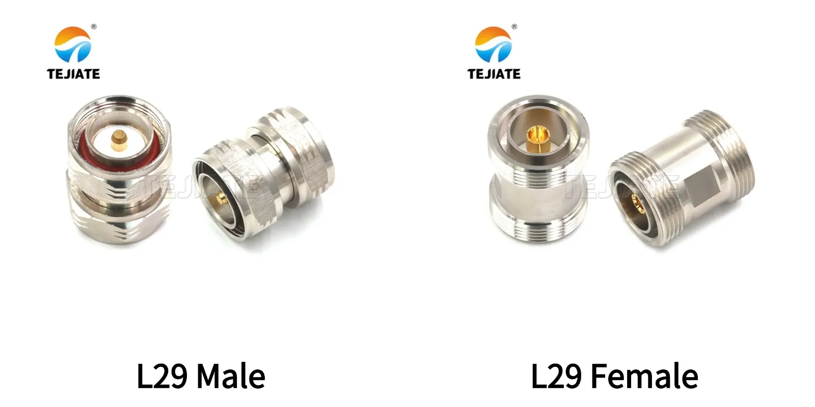
Studio photo comparing L29 / 7/16 DIN male (plug) and female (jack). Useful for the Form Factors section to clarify gender naming in DIN coaxial connectors.
Common Variants
- KF / JF (panel connectors): For bulkhead or panel mount installations.
- JJ / KK (through connectors): Straight-through couplers, male-to-male or female-to-female.
- Right-angle versions: For tight cabinet or rooftop spaces.
- Surge arrestors: Lightning protection units often use DIN 7/16 interfaces.
Quick Part Map
| Code / Form Factor | Typical Use Case |
|---|---|
| KF / JF | Cabinet or panel ports |
| JJ / KK | In-line couplers, testing |
| Right-Angle | Space-limited installations |
| Arrestor Module | Lightning protection, outdoor feeders |
Cable Pairing for Outdoor Runs
A connector is only as good as the cable it’s paired with. The 7/16 DIN connector shines when used with low-loss coaxial cables designed for outdoor telecom use.
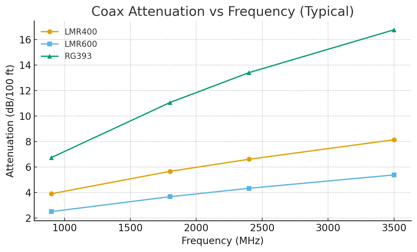
Minimal line chart showing typical attenuation (dB/100 ft) versus frequency for three telecom coaxial cables—LMR400, LMR600, and RG393—at 900, 1800, 2400, and 3500 MHz. Helps plan feeder length and cable selection.
Typical Cable Choices
- RG393: Flexible, often used inside cabinets or for short jumpers.
- LMR400: Mid-size, balances loss and handling ease; popular for rooftop runs.
- LMR600: Lower loss per meter, ideal for longer feeder cables where attenuation is critical.
Key Considerations
- Bend radius: Don’t exceed manufacturer minimums—kinking raises VSWR.
- Tensile load: Support cables with hangers to avoid stress on connector joints.
- Grounding: Use proper grounding kits at intervals to prevent lightning damage.
Attenuation Planning Table
| Frequency (MHz) | Cable Type | Attenuation per 100 ft | Best Use Case |
|---|---|---|---|
| 900 | LMR-400 | ~3.9 dB | Mid-length DAS / rooftop feeders |
| 1800 | LMR-600 | ~4.4 dB | Longer macro-site runs |
| 2400 | RG-393 | ~6.7 dB | Short jumpers inside cabinets |
| 3500 | LMR-600 | ~6.8 dB | 5G mid-band links |
Common Adapters & Use Cases
Even though the 7/16 DIN connector is rugged and reliable, there are plenty of situations where you’ll need to adapt it to other interfaces. This is common during upgrades, mixed-vendor environments, or when reusing legacy gear.
Popular Adapters
- 7/16 ↔ N-Type: Still one of the most frequent transitions, since N-Type is common on medium-power gear.
- 7/16 ↔ 4.3-10: As networks migrate to smaller, higher-density interfaces, this adapter has become critical.
- Gender changers (JJ/KK): Handy for correcting mismatched cable assemblies or test setups.
When to Use Adapters
- Temporary testing: Lab benches or field troubleshooting often need quick adapters.
- Mixed generations of equipment: Old macro stations with DIN 7/16 paired to newer 4.3-10 components.
- Legacy broadcast gear: Where replacing the entire feeder line is impractical.
When to Avoid Adapters
- Permanent outdoor links: Every adapter is an extra junction—another potential source of PIM and weather leaks.
- Critical high-power runs: Direct mating is always superior for efficiency and longevity.
7/16 DIN vs 4.3-10 vs N-Type
The RF industry has been slowly shifting away from DIN 7/16 toward newer designs like 4.3-10. That doesn’t make the DIN obsolete, but it does mean you should understand the trade-offs.
Quick Comparison
| Feature | 7/16 DIN | 4.3-10 | N-Type |
|---|---|---|---|
| Size | Large, 29 mm body | Smaller, compact | Medium |
| Torque Requirement | 25–30 N·m | 5–8 N·m | ~1.5 N·m |
| PIM Performance | Excellent (-155 dBc) | Excellent, more stable | Moderate |
| Power Handling | Very high (>1 kW) | High, optimized | Moderate |
| Port Density | Low (large ports) | High (more ports/area) | Moderate |
| Weatherproofing | IP67-68 with kits | Similar IP67-68 | Requires seals |
| Cost | Higher | Mid-range | Lower |
Takeaway:
- Stick with 7/16 DIN if you’re maintaining high-power legacy sites or broadcast towers.
- Choose 4.3-10 if you’re deploying new LTE/5G gear where port density and easier torqueing matter.
- Use N-Type for smaller, cost-sensitive links that don’t need extreme PIM suppression.
Buyer’s Checklist
Selecting the right DIN 7/16 connector (or its alternatives) isn’t just about grabbing the cheapest option online. You’ll want to go through a structured checklist.
Step-by-Step Selection Guide
- Power Rating: Know your site’s maximum transmit power. Oversizing here avoids overheating.
- Frequency Band: Match connector and cable to operating bands (700 MHz vs 3.5 GHz will affect attenuation).
- Cable Length & Type: Choose LMR400/600 or RG393 depending on run distance and flexibility needs.
- PIM Requirements: For LTE/5G multi-carrier, insist on certified low-PIM connectors.
- Weatherproofing Plan: Budget for boots, tapes, or heat-shrink kits if outdoors.
- Spare Parts & Tools: Always keep extra connectors and a torque wrench on-hand for field swaps.
Maintenance Rhythm
- Quarterly: Check torque and inspect seals.
- After major storms: Look for moisture intrusion or corrosion.
- Annual: Run PIM tests and replace worn boots/tapes.
This kind of preventive care can extend the life of your connectors and reduce costly tower climbs.
FAQs on 7/16 DIN Connectors
Q1. Is there any difference between “7/16 DIN” and “connector din 7 16”?
No—these are simply different naming conventions for the same interface. “DIN 7/16,” “7 16 connector,” and “L29 connector” all point to the same standard.
Q2. When should I use a 7 16 to N-Type adaptor? Will it increase PIM?
Use it only when connecting legacy DIN-based feeders to equipment with N-Type ports. Yes, every adapter adds a small PIM risk, so minimize where possible.
Q3. Should I migrate from 7/16 DIN to 4.3-10?
If you’re rolling out new LTE/5G gear, yes—the 4.3-10 is smaller, lighter, and easier to torque. But for high-power broadcast or legacy macro sites, DIN 7/16 still outperforms.
Q4. Is the 7/16 DIN connector waterproof?
The connector includes seals, but real-world waterproofing requires tape, heat-shrink, and weather boots for IP67/68 performance.
Q5. Which cables pair best with 7/16 DIN?
- RG393: Short cabinet jumpers
- LMR400: Mid-length rooftop feeders
- LMR600: Long-distance, low-loss runs
Conclusion
The 7/16 DIN connector (L29) isn’t the newest kid on the block, but it remains a trusted workhorse wherever high power, low PIM, and outdoor durability are non-negotiable. From macro cell towers to broadcast antennas, it continues to deliver clean, stable connections that newer, smaller designs still aim to match.
As networks evolve, you’ll see more 4.3-10 connectors replacing DIN 7/16, especially in 5G deployments. But for legacy systems, upgrades, or high-power scenarios, the DIN 7/16 is still worth every cent.
If you’re specifying hardware, make sure your choice balances power, frequency, cable type, and weatherproofing. And never skip the torque wrench—your future PIM tests will thank you.
Explore Further
If this guide has helped you understand the 7/16 DIN connector, you may also find these resources useful for comparing related RF interfaces and planning your cabling strategy:
- SMA vs BNC vs N-Type: Which RF Connector Should You Use? – side-by-side breakdown of three widely used connectors.
- RF Adapter Guide: From SMA to 110 GHz – practical overview of adapters and when to use them.
- Best Coaxial Cables 2025: RG & LMR Picks – compare loss, flexibility, and cost.
- RF Connector Selection Guide – step-by-step process to choose the right interface.
Your Project Toolbox
For engineers sourcing hardware, here are direct links to the categories most often paired with DIN 7/16 systems:
- L29 Adapter Series – full range of 7/16 DIN (L29) adapters.
- RF Connectors – SMA, BNC, N-Type, DIN, and more.
- RF Cables – pre-terminated jumpers and low-loss feeder cables.
- Outdoor RF Antennas – weather-rated solutions for rooftop and tower installs.
Bonfon Office Building, Longgang District, Shenzhen City, Guangdong Province, China

A China-based OEM/ODM RF communications supplier
Table of Contents
Owning your OEM/ODM/Private Label for Electronic Devices andComponents is now easier than ever.
