
ATNC to BNC adapter can look like a simple metal fitting, but the wrong one can quietly damage the usefulness of a test setup.
The common mistake is not that the adapter cannot mate. It usually can. The TNC thread locks, the BNC bayonet turns into place, and the signal path passes continuity. The problem appears later: the impedance was wrong, the adapter direction was misunderstood, the BNC side was selected for a video system instead of RF testing, or the adapter stack moved the measurement reference plane without anyone recording it.
That is why TNC-to-BNC conversion should not be treated as a casual “connector changer.” It is a mechanical transition between a threaded RF interface and a bayonet quick-connect interface, but it is also part of the RF path. For engineers and buyers, the practical question is not only, “Will this fit?” It is, “Will this fit the port, the cable, the impedance, the frequency range, and the way the assembly will actually be used?”
How Does a TNC to BNC Adapter Connect Threaded and Bayonet Interfaces?
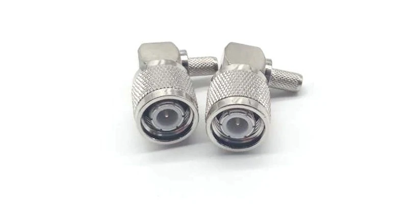
This image shows right-angle TNC RF connectors designed for coaxial cable assemblies where straight connectors may create routing stress, bending issues, or clearance problems inside RF systems.
A TNC connector uses a threaded coupling system. A BNC connector uses a bayonet lock. That mechanical difference is the main reason these adapters exist. Many RF systems still mix both interfaces because equipment generations, field hardware, antenna cables, and bench instruments do not always use the same connector family.
A typical example is a BNC instrument connected to a device or antenna lead that uses TNC. Oscilloscopes, signal generators, counters, older RF instruments, and some lab fixtures commonly use BNC ports. Ruggedized RF hardware, antenna systems, and field radio equipment may use TNC because the threaded coupling gives better mating security than a quick bayonet lock.
The adapter bridges those two connector systems. One side provides the TNC interface. The other side provides the BNC interface. That sounds simple, but it creates two separate decisions: the mechanical decision and the RF decision.
The mechanical decision answers these questions:
- Is the TNC side male or female?
- Is the BNC side male or female?
- Is the adapter straight, right-angle, bulkhead, or panel-mounted?
- Will the adapter hang directly from a port or be supported by a cable?
- Will it be installed temporarily or remain in the system?
The RF decision is different:
- Is the system 50 ohm or 75 ohm?
- What frequency range must the adapter support?
- Is the adapter used for measurement, antenna connection, signal injection, or troubleshooting?
- Will it sit inside the calibrated test path?
- Is return loss or VSWR important for this setup?
A part can pass the mechanical check and still be wrong electrically.
That happens often with BNC because BNC connectors appear in both RF test systems and video or broadcast systems. A 50 ohm RF BNC adapter and a 75 ohm video-style BNC adapter may look similar to a non-specialist buyer. In a low-frequency or rough continuity check, the difference may not be obvious. In RF measurement, antenna matching, or production validation, that small sourcing mistake can create reflected energy, inconsistent results, or unexplained test variation.
Mechanical conversion is not the same as RF compatibility
A TNC to BNC adapter is not a universal RF fix. It does not correct impedance mismatch. It does not remove the loss from a poor cable. It does not make a damaged port suitable for repeatable measurements. It only creates a physical and electrical bridge between two connector interfaces.
That distinction matters in troubleshooting.
If a technician connects a TNC antenna cable to a BNC test instrument and sees a weak signal, the adapter is only one possible cause. The issue may come from the cable type, cable length, connector wear, antenna mismatch, calibration boundary, or an impedance error somewhere else in the chain.
This is similar to RG cable selection. A cable is not correct just because the outside diameter looks close or the connector can be installed. The impedance, dielectric, shielding, attenuation, connector fit, and application all matter. The same logic applies here. The adapter should be treated as one part of the RF path, not as an isolated hardware item.
For a buyer, the better sourcing habit is to write the actual requirement instead of a short search phrase. “TNC to BNC adapter” is useful for searching. It is not enough for purchasing.
A clearer line item would be:
TNC male to BNC female adapter, 50 ohm, straight body, DC–6 GHz, for RF test equipment transition.
That one sentence removes several common risks. It defines direction, gender, impedance, body style, frequency range, and application. A supplier can check the part against the RF use case instead of guessing from a vague connector name.
Where TNC-to-BNC transitions commonly appear
TNC-to-BNC adapters are common in mixed RF environments rather than brand-new clean-sheet systems. They often appear when the equipment was not designed as one complete connector ecosystem.
Common use cases include:
- Connecting BNC test equipment to a TNC antenna cable
- Connecting a TNC device port to a BNC cable
- Using rugged TNC field hardware with bench instruments
- Building field adapter kits for service technicians
- Testing legacy equipment without replacing existing cable assemblies
- Temporarily adapting a prototype before the final cable design is confirmed
Temporary use is where the adapter is most convenient. A lab user can quickly connect a device under test, take a measurement, and remove the adapter later. But for production, vibration, panel-mounted equipment, or repeated testing, a short custom cable assembly may be safer than a rigid adapter hanging from the port.
How Do You Choose the Correct TNC-to-BNC Direction?
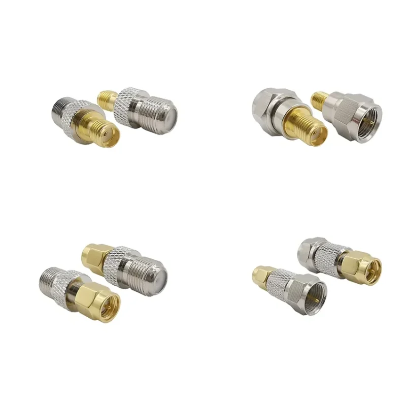
The phrase “TNC to BNC” is often used loosely. In real purchasing, it is not loose at all.
A TNC female device port does not need the same adapter as a TNC male cable. A BNC female instrument input does not need the same adapter as a BNC male cable end. The adapter must be selected from the installed interface outward.
Start with the fixed side. If the device already has a TNC female port, the adapter must have a TNC male side. If the existing cable has a TNC male plug, the adapter must have a TNC female side. Only after that should you choose the BNC side.
This order prevents one of the most common buying mistakes: searching “tnc to bnc adapter,” seeing a product photo that looks close, and ordering before checking the actual port gender.
With RF connectors, gender is normally defined by the center contact, not only the outer shape. A male connector usually has a center pin. A female connector usually has a center socket. The coupling nut or outer shell can confuse new buyers, especially when panel jacks, bulkhead versions, or reverse-polarity connector families are involved. For standard TNC and BNC adapters, inspect the center contact and the mating interface before ordering.
TNC-to-BNC adapter direction matrix
Use this matrix as a practical check before sending an RF adapter inquiry. It is not a substitute for drawing review, but it catches the most common direction mistakes.
| Installed TNC Side | Installed BNC Side | Likely Adapter Needed |
| TNC female device port | BNC male cable | TNC male to BNC female |
| TNC male cable | BNC female instrument | TNC female to BNC male |
| TNC female antenna port | BNC female test instrument | TNC male to BNC male |
| TNC male device lead | BNC male cable | TNC female to BNC female |
| Unknown port | Unknown port | Inspect center contact and coupling style first |
The table is intentionally simple. It forces the buyer or engineer to name both installed sides before selecting the adapter. That one step can prevent a wrong shipment, especially when the request is passed from engineering to purchasing and then to a supplier.
In internal BOMs, avoid writing only:
TNC/BNC adapter
That description leaves too much room for error.
A better BOM note would be:
RF adapter, TNC male to BNC female, 50 ohm, straight body, rated for target test frequency, for connecting TNC female device port to BNC male test cable.
This kind of wording is longer, but it is cheaper than receiving the wrong adapter before a test deadline.
Do not assume “TNC to BNC” and “BNC to TNC” are identical
Search engines may treat “TNC to BNC adapter” and “BNC to TNC adapter” as closely related. Suppliers may even use both phrases on the same product page. That does not mean every physical adapter is interchangeable.
For a straight adapter, the two connector families are still on opposite ends, but the gender combination controls whether the part can actually mate with the installed hardware. For example, a TNC male to BNC female adapter and a TNC female to BNC male adapter solve different problems. Both may appear under similar keywords. Only one may fit the equipment in front of you.
For field technicians, the safest habit is to record the actual connection path:
Device TNC female port → adapter TNC male side → adapter BNC female side → BNC male cable.
That format makes the direction visible. It also helps later if a test result must be repeated, because the adapter is part of the RF path, not just a mechanical accessory.
If the setup is used for measurement, record the adapter model as well. Two adapters with the same interface names can behave differently at higher frequencies because of internal geometry, plating condition, dielectric support, machining tolerance, and wear from repeated mating.
A continuity check will not show those differences. A VNA sweep might.
For low-risk bench troubleshooting, a general RF adapter may be enough. For repeatable validation, write down the adapter direction, impedance, frequency range, calibration state, and where the adapter sits in the measurement chain. That small record can save hours when two engineers test the same device and get slightly different numbers.
How Should 50 Ohm Matching Guide TNC to BNC Adapter Selection?
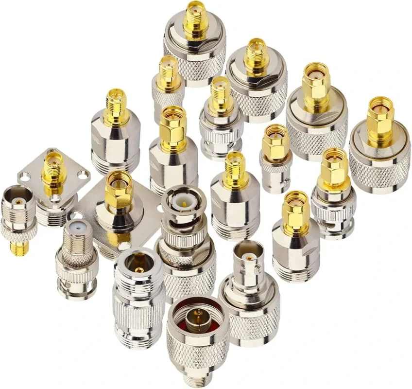
The adapter direction may be correct, but the RF system can still be wrong if impedance is ignored.
Most RF test and antenna systems using TNC and BNC hardware are built around 50 ohm transmission paths. That does not mean every BNC adapter on the market is automatically a 50 ohm RF adapter. BNC also appears in 75 ohm video, broadcast, CCTV, and measurement environments. The outside connector style may look familiar, but the electrical intent may be different.
For a technician doing a quick continuity check, this may not matter. For a test engineer comparing return loss, insertion loss, antenna match, or output power, it matters quickly.
A TNC to BNC adapter should match the impedance family of the system. If the cable is RG58, RG142, RG316, or another 50 ohm coaxial cable, the adapter should also be specified as 50 ohm. If the BNC side belongs to a 75 ohm video cable or broadcast device, do not assume it belongs in a 50 ohm RF bench setup.
Avoid mixing RF test adapters with video BNC adapters
The trap usually starts with the BNC side.
A buyer sees “BNC adapter” in a catalog and assumes it fits the request. Mechanically, it may. Electrically, it may not be the adapter the engineer expected. A BNC adapter intended for video distribution, CCTV service, or general low-frequency connection may not be the right choice for a 50 ohm RF test chain.
The result is rarely dramatic at first. The setup may still show a signal. The device may still power through a basic check. The connector may not heat, spark, or fail visibly. Instead, the numbers become less trustworthy. A return loss measurement looks worse than expected. Two test benches disagree. A cable that passed last week appears marginal after someone replaced the adapter.
That is why the adapter should be written clearly in the BOM or purchase request.
Use:
TNC male to BNC female adapter, 50 ohm, for RF test equipment, target frequency DC–6 GHz.
Avoid:
TNC BNC converter.
The first request gives the supplier enough information to check the part. The second request only names two connector families and leaves the important decisions open.
Confirm the cable before blaming the adapter
If the RF result is poor, the adapter is not always the guilty part.
The cable may be the limiting factor. A short RG316 jumper, a longer RG58 cable, a semi-rigid RG402 assembly, and a 75 ohm RG59 video cable do not behave the same just because they all use coaxial construction. Cable impedance, attenuation, shield construction, bend history, connector termination, and length all affect the signal path.
A TNC to BNC adapter only adds one transition. The complete path may include:
- instrument output
- BNC cable
- BNC-to-TNC adapter
- TNC device port
- internal PCB transition
- antenna or load
If any part is mismatched, worn, bent, poorly terminated, or outside its practical frequency range, the adapter may be blamed unfairly.
For production or incoming inspection, label the full path. Do not only record the adapter part number. Record the cable type, cable length, connector count, adapter count, and test frequency. That record helps separate a real adapter issue from a cable or setup issue.
How Does a TNC to BNC Adapter Affect RF Measurement Accuracy?
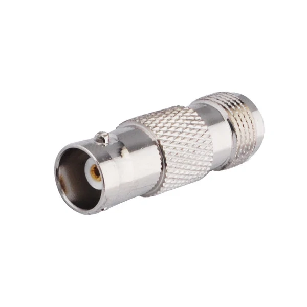
This image shows a straight RF coaxial adapter used to convert between BNC and TNC connector interfaces. It is commonly used for RF test equipment, antenna cables, field service kits, and mixed connector systems.
An adapter adds another interface. That is the simplest way to think about it.
Every interface can add a small amount of insertion loss and reflection. At low frequency, the difference may be small enough to ignore in a rough functional check. As frequency increases, the same adapter becomes more visible in the measurement. Internal geometry, dielectric support, plating condition, center pin alignment, and repeated mating wear all become part of the result.
This does not mean adapters should be avoided completely. They are useful. They save time. They help connect mixed equipment. But they should not be invisible in the test record.
Watch VSWR and return loss when frequency increases
A continuity meter can tell whether the center conductor connects and whether there is a short to shield. It cannot tell whether the adapter is clean enough for a higher-frequency RF measurement.
For RF work, S11 and return loss show how much signal is reflected back from the transition. S21 or insertion loss shows how much signal passes through the adapter path. VSWR is another way to express mismatch. These measurements are not always needed for a simple service adapter, but they are useful when the adapter sits inside a repeatable test setup.
A practical rule is simple:
If the adapter is only used for quick troubleshooting, mechanical fit and impedance may be enough.
If the adapter is used for comparison data, production validation, antenna tuning, or VNA measurement, record and test it.
The issue becomes worse when adapters are stacked. One adapter may be acceptable. Two or three adapters, plus several cables, can move the reference plane and add small errors that look like device variation. In that situation, the device under test may not be the real reason for the poor result.
RF path penalty table
Use this table to judge how much attention the adapter deserves in the setup.
| Setup Condition | Adapter Risk | Recommended Action |
| Low-frequency continuity check | Low | Confirm fit, gender, and no short |
| Temporary RF bench connection | Medium | Confirm 50 ohm impedance and frequency rating |
| Antenna tuning or return loss check | Medium to high | Include adapter in test record |
| VNA measurement after calibration plane | High | Treat adapter as part of the measured path |
| Multiple adapters stacked together | High | Reduce transitions or use a custom cable |
| Production comparison testing | High | Standardize adapter model and inspection method |
The table is not a laboratory standard. It is a sourcing and test-control tool. Its job is to stop a small adapter change from becoming an unexplained measurement difference.
When Should You Use a TNC to BNC Adapter Instead of a Cable Assembly?
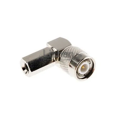
This image shows a right-angle TNC RF adapter suitable for compact RF equipment, antenna connections, and test setups where cable routing direction and mechanical stress need to be controlled.
A rigid adapter is useful when the connection is short, supported, and temporary. It works well on a bench where the equipment is stable and the adapter is not carrying cable weight or side load. It is also convenient in field kits where one technician may need to connect several connector families during troubleshooting.
But a rigid adapter is not always the better long-term choice.
If the TNC or BNC port is mounted on a PCB, small enclosure, thin panel, or sensitive instrument front panel, a heavy cable hanging from a rigid adapter can create leverage. The connector may loosen over time. The panel nut may shift. The center contact may wear unevenly. In mobile or vibrating equipment, the problem becomes more serious.
A short cable assembly can reduce that stress. It gives the connection some flexibility, lets the cable bend away from the port, and helps prevent the adapter body from acting like a lever.
Adapter vs cable assembly decision table
| Condition | Better Choice | Reason |
| Temporary bench test | TNC to BNC adapter | Fast conversion and easy removal |
| Small PCB-mounted port | Cable assembly | Reduces leverage on the connector |
| Field service kit | Adapter or short cable | Depends on space and strain relief |
| Repeated production test | Tested cable assembly | Improves repeatability |
| Space-limited enclosure | Right-angle adapter or short cable | Controls routing stress |
| Precision RF validation | Lowest-interface path | Minimizes uncertainty |
A good RF setup is not always the one with the fewest parts. It is the one with the fewest uncontrolled parts.
For a quick bench check, the adapter may be the cleanest option. For a permanent build, repeated test fixture, or customer-facing assembly, a purpose-built cable can be more stable. The decision should consider electrical performance and mechanical life together. If the setup will be moved, bent, pulled, or repeated hundreds of times, the cable assembly usually deserves serious consideration.
How Do TNC to BNC Adapters Compare With Other RF Adapter Options?
A TNC to BNC adapter usually shows up when the RF setup is not perfectly clean on paper. One side is built around threaded TNC hardware. The other side still uses BNC, often because the bench instrument, test cable, or older service fixture was designed that way.
That is different from a TNC to SMA adapter. SMA is smaller, more common on compact RF modules, PCB-mounted hardware, GNSS units, Wi-Fi devices, and small antenna leads. If a cable is hanging from an SMA port, mechanical stress becomes a bigger concern. A rigid TNC-to-SMA adapter may fit, but it can put too much leverage on a small connector.
N to TNC adapters solve another problem. N-type connectors are larger and more common around antenna systems, outdoor RF equipment, and bigger coaxial cables. They are not usually selected just to connect a quick lab instrument. They are selected because the system already uses larger RF hardware.
TNC to BNC sits between those worlds. It is not as compact as SMA conversion and not as heavy as N-type conversion. Its value is practical: connecting a threaded interface to a bayonet interface without rebuilding the whole cable path.
| Adapter path | Usually used for | Watch carefully |
| TNC to BNC | Bench instruments, field kits, mixed RF systems | BNC impedance and gender |
| TNC to SMA | Compact modules and small antenna ports | Port stress and SMA size |
| N to TNC | Antenna-side or larger RF equipment | Weight, size, and cable support |
| BNC to SMA | Instruments to compact devices | 50 ohm / 75 ohm BNC confusion |
The table is only a starting point. The real selection still depends on the installed port, cable type, frequency range, and whether the adapter will be moved repeatedly.
How Can You Test a TNC to BNC Adapter Before Use?
Do not start with the VNA. Start with your eyes.
Check the TNC thread first. Look for flattening, burrs, cross-thread marks, or plating damage. Then check the BNC side. The bayonet slots should lock smoothly without a loose, half-engaged feel. If the adapter has already been used in a lab drawer for years, assume it may have been over-tightened, dropped, mixed with 75 ohm hardware, or connected to dirty cables.
The center contact matters more than the outer shell. A bent pin, widened socket, pushed-back contact, cracked dielectric, or metal shaving inside the interface can create an intermittent fault. Some problems only appear after the cable is moved.
A basic inspection sequence can be short:
- confirm TNC and BNC gender
- check thread and bayonet condition
- inspect center contact alignment
- look for cracked dielectric
- test center continuity
- test shield continuity
- confirm no center-to-shield short
That is enough for a service kit or non-critical troubleshooting part. For measurement use, add S-parameter checking. S11 or return loss shows the reflected portion of the signal. S21 or insertion loss shows the transmission through the adapter path. If the adapter sits after calibration, it is part of the measured device path whether the report says so or not.
How Do You Use TNC to BNC Adapters With Test Equipment?
Many bench instruments use BNC because it is fast. Oscilloscopes, signal generators, counters, and older RF tools are full of BNC ports. The device under test may use TNC because the cable needs a threaded lock or because the system was built for field use.
That mix is normal. The mistake is treating the adapter as invisible.
For a quick signal check, it may not matter much. For return loss, antenna tuning, VNA comparison, or production testing, the adapter position should be written down. If one engineer calibrates with the adapter in place and another adds it after calibration, the two results may not match. The device may look unstable when the setup is the real variable.
A useful test note is plain and boring:
BNC instrument port → BNC male cable → BNC female to TNC female adapter → TNC male device cable.
That line tells the next person exactly what was tested. It also gives purchasing the information needed to reorder the same interface path.
How Do You Specify the Right TNC to BNC Adapter for Procurement?
A short product name is not a specification. “TNC BNC adapter” may be fine for a search box, but it is weak for a purchase request.
Send the supplier the connection path. Then add the electrical and mechanical requirements.
A clear request could be:
TNC male to BNC female adapter, 50 ohm, straight body, DC–6 GHz, for connecting a TNC female device port to a BNC male RF test cable. Quantity: 200 pcs.
If the adapter will be used in a repeated test fixture, add:
Please confirm frequency rating and recommended RF inspection method. Adapter will be used for comparison testing, not only mechanical conversion.
If the adapter will be used in the field, add:
Repeated mating expected. Please confirm thread condition, bayonet lock quality, packaging label, and whether bulkhead or cable assembly versions are available.
That extra detail avoids the usual back-and-forth: wrong gender, wrong BNC impedance, wrong body style, or a part that fits one bench cable but not the actual device port.
Why Are TNC to BNC Adapters Still Useful in Mixed RF Systems?
Mixed connector systems are not going away. Labs keep older instruments because they still work. Field teams keep adapter kits because the next site may not match the last one. Production teams may test the same product with a temporary fixture before the final cable assembly is released.
A TNC to BNC adapter is useful because it lets those systems talk to each other without forcing a full cable redesign. It gives access, speed, and flexibility.
The limit is also clear. If the setup becomes permanent, heavy, vibration-prone, or measurement-sensitive, the adapter should be controlled like any other RF component. Sometimes the better answer is not another adapter. It is a short TNC-to-BNC cable assembly with strain relief and a known test result.
FAQ
Is a TNC to BNC adapter the same as a BNC to TNC adapter?
The terms are often used together, but the physical adapter still has a specific gender on each side. A TNC male to BNC female adapter will not solve the same problem as a TNC female to BNC male adapter. Always check the installed ports first.
Can I use a TNC to BNC adapter with 50 ohm RF equipment?
Yes, if the adapter is specified as 50 ohm and rated for the frequency you need. Do not assume every BNC adapter is suitable for RF testing, because BNC hardware is also common in 75 ohm video systems.
Does the adapter affect RF performance?
It can. One good adapter may add only a small change, but the effect becomes more noticeable at higher frequencies, in return loss testing, or when several adapters are stacked together. For measurement work, record the adapter position.
When is a cable assembly better than a rigid adapter?
Use a cable assembly when the port is small, panel-mounted, PCB-mounted, exposed to movement, or carrying cable weight. The short cable reduces leverage and usually makes the installation more forgiving.
What should I include in a quotation request?
Include TNC gender, BNC gender, impedance, frequency range, body style, application, quantity, and any test requirement. A complete line item is easier to quote correctly than a vague phrase like “TNC BNC converter.”
Final Buying Note
Before ordering a TNC to BNC adapter, write the real connection path from port to cable. Then check impedance, frequency range, gender, and mechanical load. If the adapter is only for quick troubleshooting, a standard RF adapter may be enough. If it will stay in a fixture, sit after calibration, or support a heavy cable, treat it more carefully.
For TEJTE RF adapter sourcing, send the installed port type, mating cable side, operating frequency, impedance, and quantity. That information is usually enough to prevent the common mistakes before the adapter reaches the bench.
