
An SMB connector can mate correctly, pass a continuity check, and still be the wrong cable termination.
The problem usually starts at the rear of the connector, not at the SMB mating interface. A buyer sees “SMB connector for RG174,” the production team sees a crimp ferrule that looks close enough, and the first assembly appears normal. Then the lot reaches pull testing or RF inspection. Ferrules move, braid strands escape, center contacts sit at different depths, or return loss changes from sample to sample.
For an SMB cable connector, the front interface is only one part of the specification. Cable dimensions, ferrule geometry, center-contact termination, strip dimensions, tooling, and inspection method all belong to the same assembly process.
That matters even more with miniature coax such as RG174 and RG316, where a small dimensional mismatch leaves less room for the termination process to absorb variation.
Which Cable Dimensions Must Match the SMB Connector First?
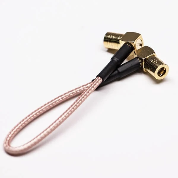
Factory-terminated miniature coax jumper featuring right-angle SMB connectors and RG316-style cable for space-limited RF connections.
“Suitable for RG174” is useful shorthand. It is not enough information to release a connector into production.
RG designations identify cable families, but connector termination depends on physical dimensions. Two cables sold under the same general RG designation can also vary slightly by manufacturer, conductor construction, jacket material, or production tolerance.
Before approving an SMB connector RG174 or SMB connector RG316, check the actual cable drawing against the connector drawing.
At minimum, record:
- jacket outside diameter
- braid or shield outside diameter
- dielectric outside diameter
- center conductor diameter
- solid or stranded center conductor
- shield construction
- jacket material
The connector side needs the same level of attention. Check the ferrule inside diameter, rear-body bore, dielectric support area, center-contact termination geometry, jacket entry, and available space for strain relief or heat shrink.
Measure the cable instead of matching only the RG number
A common purchasing mistake is to treat the RG designation as if it defines the entire connector termination.
Consider a connector marketed as an SMB crimp connector RG174. The description may tell you the intended cable family, but it does not tell production which ferrule cavity to use, how far the dielectric should enter the body, or whether the center contact is crimped or soldered.
The same problem appears with an SMB crimp connector RG316.
RG174 and RG316 are both small coaxial cables, but they should be treated as separate termination interfaces until the actual cable and connector dimensions have been compared. The useful question is not:
“Does this connector say RG174 or RG316?”
It is:
“Does this exact connector P/N fit this exact cable construction?”
That distinction becomes important during substitutions. A purchasing team may find another SMB connector with the correct front interface and similar appearance. If the ferrule, rear bore, or center-contact geometry changes, it is not a drop-in process replacement.
For a wider comparison of miniature coax construction before selecting the connector, the existing RG Cable Guide can remain the cable-family reference. The termination drawing should still control the final connector decision.
Check ferrule and rear-body dimensions before approving a substitute
The ferrule deserves particular attention because a visually acceptable crimp can hide a poor mechanical joint.
If the ferrule is too large, the tool may close fully while failing to capture enough braid. The assembly can look neat and still move during a pull test.
If the ferrule or rear body is too small, the operator may force the cable into the connector, damage the jacket, disturb the shield, or deform the dielectric.
A simple compatibility card prevents many of these errors from reaching the workstation.
SMB Cable Compatibility Card
| Check | Cable Data | Connector Requirement | Status |
| Jacket OD | Record actual/drawing value | Rear entry must accept cable | Pass / Review |
| Braid OD | Record value | Match shield capture area | Pass / Review |
| Dielectric OD | Record value | Match internal support | Pass / Review |
| Center conductor OD | Record value | Match center contact | Pass / Review |
| Ferrule ID | — | Connector drawing value | Pass / Review |
| Rear-body bore | — | Connector drawing value | Pass / Review |
| Strip dimensions | — | Approved assembly drawing | Confirmed |
| Center contact | Solid/stranded conductor | Crimp or solder as specified | Confirmed |
| Approved cable family | Cable P/N | Connector P/N | Released / Hold |
This card is more useful than a BOM line that only says “SMB connector, RG174.”
For production sourcing, keep both the cable manufacturer/P/N and connector P/N on the approved record. Otherwise a later cable substitution can silently change the termination even though the commercial description appears unchanged.
How Do You Confirm Plug, Jack, and Center Contact Before Termination?
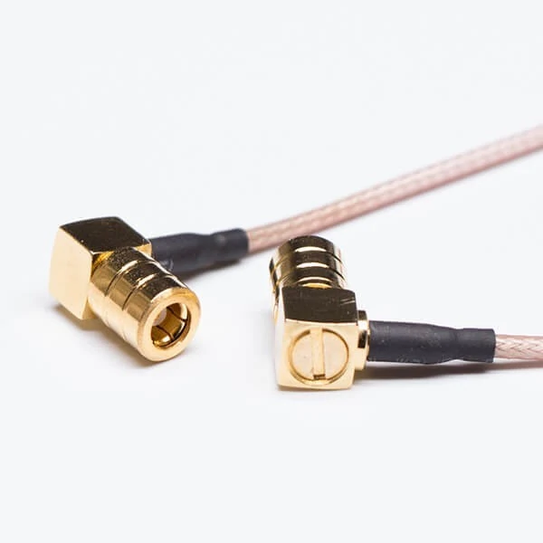
Detailed view of right-angle SMB cable connectors used to inspect interface geometry, contact position, cable entry, and termination workmanship.
Cable compatibility does not prevent an interface mistake.
SMB terminology can become confusing when suppliers, marketplaces, and drawings use “male,” “female,” “plug,” and “jack” inconsistently. Production should therefore verify the actual mating geometry rather than rely only on a product title.
Confirm three items independently:
- connector family — SMB
- outer mating role — plug or jack
- center contact — pin or socket
Then confirm whether the connector belongs on the cable side or equipment side.
Separate shell gender from center-contact geometry
The safest incoming-inspection method is to compare the connector against the approved drawing and, when practical, an approved mating sample.
Do not release a lot because the connector “looks like the previous SMB.”
Check:
- plug or jack geometry
- center pin or socket
- mating reference dimensions
- straight or right-angle body
- intended 50-ohm RF system
- drawing revision
- physical mating sample where available
This is especially useful when purchasing from a new supplier. A photograph can hide small interface details, and marketplace naming conventions are not a substitute for dimensional confirmation.
The existing TEJTE SMB connector reference can handle the broader interface background; this termination guide is concerned with making sure the exact cable-end hardware arriving at production matches the approved assembly.
Keep straight and right-angle versions separate
A right angle SMB crimp connector should not be treated as the same production part with the body simply bent 90 degrees.
The front SMB interface may remain the same, but the rear termination architecture can change. Ferrule dimensions, contact insertion method, cable exit direction, assembly sequence, and tool access may differ.
For this reason, a straight SMB male crimp connector and a right-angle version should normally have separate approved part numbers and work instructions unless the manufacturer explicitly specifies a shared termination process.
A compact incoming verification table can catch the error before stripping any cable.
| Verification | Equipment Port | Cable Connector |
| SMB family confirmed | Yes / No | Yes / No |
| Plug / jack | Record | Record |
| Pin / socket | Record | Record |
| Straight / right-angle | Record | Record |
| 50 Ω path | Confirm | Confirm |
| Drawing reference | Record | Record |
| Physical sample checked | If available | If available |
Once the cable dimensions and mating interface are frozen, the next question is the actual termination route: does the center contact crimp, solder, or use a mixed crimp-and-solder process?
That decision needs to come from the connector assembly drawing—not from the words “SMB crimp connector” in the product title.
Should the Center Contact Be Crimped, Soldered, or Both?
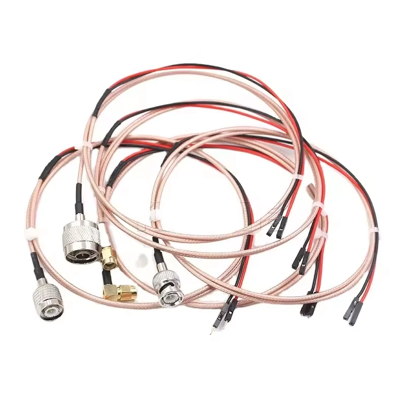
Collection of coaxial cable assemblies with multiple RF connector configurations, illustrating factory termination for controlled mechanical performance and RF testing.
The words SMB crimp connector do not automatically mean that every part of the connector is crimped.
Some cable-mounted SMB designs use a crimped center contact and a crimped ferrule. Others use a soldered center conductor followed by a ferrule crimp over the braid. A third design may use a captivated contact or another assembly sequence.
The connector assembly drawing should decide the process.
Before production starts, separate two operations:
Center conductor termination
- crimp
- solder
- specified insertion depth
- final contact position
Outer shield termination
- ferrule crimp
- braid fold-back
- braid capture
- rear-body seating
Mixing these two decisions is a common source of bad work instructions.
Read the connector drawing before selecting the process
If a center contact is designed for crimping, the contact barrel and conductor must match the approved crimp cavity.
If it is designed for soldering, solder quantity and heat become process variables.
This matters with small coaxial cable because excessive soldering heat can move or soften the dielectric near the contact. Too much solder can also wick backward along the conductor, creating a locally stiff section immediately behind the connector.
For PTFE-based miniature coax, control:
- soldering temperature
- dwell time
- solder volume
- conductor insertion depth
- dielectric movement
- solder wicking
- final contact position
A termination that looks mechanically complete may still have the center contact sitting too far forward or too far back.
For production control, document the complete process route:
Cable → Strip → Braid preparation → Center contact termination → Contact inspection → Body insertion → Ferrule crimp → Strain relief → Electrical test → RF test
That sequence becomes especially useful when troubleshooting. If an assembly fails, the process record shows where to investigate instead of treating “crimping” as one single operation.
How Should Strip Dimensions Be Transferred From Drawing to Work Instruction?
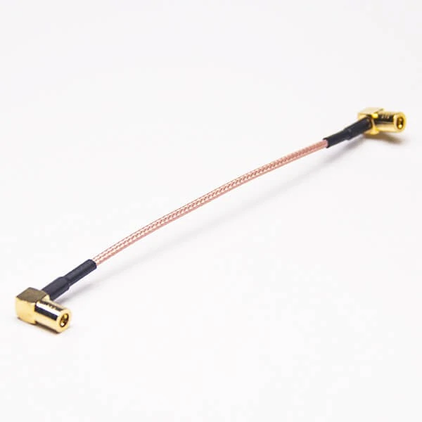
Full view of a miniature coax cable assembly terminated with two right-angle SMB connectors, showing cable length, connector orientation, and strain-relief construction.
“Strip 5 mm” is not an adequate instruction for an SMB cable termination.
A connector drawing may depend on several separate dimensions:
- jacket strip length
- braid exposure
- dielectric strip length
- center conductor exposure
- braid fold-back length
- final center-contact position
Each dimension should use one clearly defined datum from the cable end.
Keep braid strands out of the contact area
Loose braid strands are small enough to disappear during assembly and serious enough to create a short later.
Inspect for:
- strands entering the center-contact cavity
- uneven braid fold-back
- missing shield strands
- braid trapped against the dielectric
- insufficient shield coverage
Do this before the ferrule hides the termination.
Once heat shrink or strain relief is installed, some workmanship defects become difficult to see without destroying the assembly.
Control dielectric position after stripping
The dielectric should not simply be “close enough.”
If too much dielectric is removed, the center conductor loses support and the transition geometry changes. If too little is removed, the contact may not reach its intended axial position.
Either condition can affect RF repeatability.
A practical workstation record can look like this:
| Dimension | Drawing Symbol | Nominal | Tolerance | Inspection Tool |
| Jacket strip | A | Per drawing | Per drawing | Caliper / gauge |
| Braid exposure | B | Per drawing | Per drawing | Optical / gauge |
| Dielectric strip | C | Per drawing | Per drawing | Caliper |
| Center conductor | D | Per drawing | Per drawing | Gauge |
| Braid fold-back | E | If required | Per drawing | Visual / gauge |
| Final contact position | F | Per drawing | Per drawing | Depth gauge |
There should not be a single “universal SMB stripping dimension” copied across different connectors.
The correct dimensions belong to the specific cable-and-connector combination.
Which Crimp Tool and Die Belong to This SMB Connector?
The tool should be selected from the connector requirement, not from the operator’s memory of a similar SMB part.
An SMB crimp tool may need two different functions:
- a cavity for the center contact
- a hex cavity for the ferrule
Those dimensions are not interchangeable.
The fact that one cavity physically closes around the part does not prove it is the correct tooling.
Verify the complete tooling setup before the first lot
Record:
- tool frame part number
- die set part number
- center-contact cavity
- ferrule cavity
- ratchet function
- full closure
- die wear
- calibration or verification status
- crimp position
A useful rule is to avoid selecting the ferrule hex size only from the RG cable designation.
An SMB connector RG174 from one manufacturer may not necessarily use the same ferrule geometry as another RG174-compatible connector. The same applies to RG316.
Use the connector drawing and the qualified process.
SMB Crimp Tool Approval Matrix
| Item | Required | Actual | Result |
| Tool frame | Approved P/N | Record | Pass / Hold |
| Die set | Approved P/N | Record | Pass / Hold |
| Contact cavity | Drawing/process spec | Record | Pass / Hold |
| Ferrule cavity | Drawing/process spec | Record | Pass / Hold |
| Tool verification | Current | Record | Pass / Hold |
| Full-cycle ratchet | Functional | Record | Pass / Hold |
| Cable P/N | Approved | Record | Pass / Hold |
| Connector P/N | Approved | Record | Pass / Hold |
This matrix is particularly useful when the same workstation handles several miniature coax assemblies. It prevents a die left from the previous job from becoming an invisible process change.
How Can the Crimp Be Inspected Without Cutting Every Assembly Apart?
Cross-section inspection is useful during qualification, but production cannot destroy every cable.
Routine inspection therefore needs a strong non-destructive visual standard.
Check the ferrule under magnification.
Look for:
- symmetrical compression
- complete crimp
- cracks
- split ferrule
- sharp flash
- rear-body damage
- cable entering off-center
Then inspect both ends of the ferrule.
Excessively crushed jacket, protruding braid, pulled-back jacket, or a ferrule positioned too far forward can all indicate an unstable termination.
The center contact also needs inspection.
Reject or review an assembly if the contact:
- is excessively recessed
- projects farther than the approved reference
- moves axially
- rotates when the design should retain it
- contacts the outer body
- shows visible dielectric disturbance
Visual inspection does not prove RF performance, but it can prevent obvious process defects from reaching electrical testing.
What Pull Test Should Be Defined for the Finished Termination?
Avoid publishing one universal pull-force value for every SMB connector.
Cable retention depends on the cable construction, ferrule geometry, braid capture, jacket material, rear-body design, and crimp tooling.
The acceptance value should therefore come from the customer requirement, connector qualification, validated internal process, or applicable project specification.
Just as important, define how the test is performed.
Record:
- where the connector is held
- whether the cable is pulled axially
- pull speed
- gauge length
- test duration
- destructive or non-destructive method
- peak load
- failure location
Do not confuse cable retention with SMB mating retention.
Cable retention asks whether the cable pulls out of the connector termination.
SMB mating retention asks whether the plug separates from the mating jack.
They are different mechanical tests.
A failed pull sample should also record the failure mode. A single force number is much less useful than knowing whether the braid slipped, ferrule moved, jacket stretched, or center contact shifted.
Why Can a Connector Pass Continuity but Still Fail an RF Test?
Continuity is only the first electrical gate.
It can identify:
- open center conductor
- open shield path
- center-to-shield short
It does not fully detect:
- impedance discontinuity
- incorrect dielectric position
- poor braid transition
- inconsistent contact depth
- local geometry changes
- frequency-dependent mismatch
This is why an assembly can show a clean continuity result and still produce poor return loss or unstable insertion loss near the required operating band.
For RF-sensitive production, sweep the completed assembly across the required band rather than checking only one convenient frequency.
Insertion-loss measurement can follow an established RF connector test method such as IEC 61169-1-2, which covers insertion-loss measurement for RF connectors, including cable connectors and adapters.
For return-loss verification, record at least:
- S11
- S22 where appropriate
- full test range
- worst-case frequency
- calibration planes
- fixture or reference assembly
A practical qualification method is to compare the terminated sample against a known-good assembly.
| Frequency Point | Reference IL | Sample IL | ΔIL | Acceptance |
| Low band | Record | Record | Calculate | Project limit |
| Mid band | Record | Record | Calculate | Project limit |
| Application band | Record | Record | Calculate | Project limit |
| Upper band | Record | Record | Calculate | Project limit |
| Worst case | Record | Record | Calculate | Project limit |
The value of this comparison is not a universal allowable delta. It is process visibility.
If several assemblies made from the same cable, connector, strip dimensions, and tooling begin moving away from the approved reference, production has evidence that something in the termination process has changed.
That is far more useful than waiting for an end customer to report that the cable “connects but the RF signal is worse.”
Control Right-Angle SMB Assemblies Before Cable Routing Begins
A 90-degree connector solves a packaging problem, but it can create a routing problem if the cable exit direction is not defined early.
A right angle SMB crimp connector is useful where the cable must run parallel to a PCB, pass beneath a low enclosure lid, or leave a dense RF module without adding unnecessary height. That does not mean any 90-degree version can replace a straight connector.
The drawing should define the viewing direction, exit quadrant, nearby component clearance, first clamp point, and cable no-bend area.
Keep the first bend away from the connector tail
Do not force the coax into its final route immediately behind the ferrule.
Allow enough straight cable for the termination and strain-relief area, then apply the cable manufacturer’s bend-radius requirement. Tight bending directly behind the connector can place repeated mechanical stress on the braid capture and center-conductor transition.
If the connector can rotate after mating, also decide whether field adjustment is acceptable. Rotating the body after installation may twist the coax rather than simply redirect it.
For fixed OEM assemblies, specify cable-exit orientation on the drawing instead of leaving it to the assembler.
How Should a 50-Ohm SMB Cable Connector Be Verified?
Do not verify impedance by reading “50 Ω SMB” from the connector description alone.
Check the complete path:
PCB or device → SMB interface → cable termination → coax → opposite connector → load
The current IEC sectional specification for 50-ohm Type SMB connectors is IEC 61169-10:2024. It covers mating-face dimensions, gauging, selected tests, inspection requirements, and recommended performance characteristics for the SMB series; IEC lists the standard SMB series operating frequency as up to 4 GHz.
That figure should not be used to invent a rating for every commercial SMB assembly. If a supplier claims a particular connector or finished cable works at another frequency, request the product-specific specification or test data.
Termination still matters.
A nominally correct 50 ohm SMB cable connector can show poor RF behavior if:
- the dielectric position changes
- center-contact depth is inconsistent
- braid termination is uneven
- stripping dimensions vary
- the connector body is not fully seated
The front interface does not compensate for a poor rear transition.
Qualify the First Article Before Operators Start Volume Crimping
The first article should approve a process, not just a connector.
Freeze these items together:
- cable manufacturer and P/N
- SMB connector P/N
- tool frame
- die set
- stripping dimensions
- center-contact process
- ferrule process
- operator work instruction
- inspection method
Changing one of them later may change the termination.
Use destructive inspection before production release
A production lot cannot be cut apart, but qualification samples can.
Depending on project risk, first-article inspection may include:
- pull testing
- cross-section inspection
- center-contact retention
- ferrule examination
- continuity
- isolation
- insertion loss
- return loss
IEC 61169-1-2:2019 provides insertion-loss test methods applicable to cable RF connectors and RF connector adapters, making it a useful authority when a project needs a defined connector insertion-loss measurement method.
A simple release record keeps the acceptance logic visible.
| Test | Sample Level | Acceptance Basis | Evidence |
| Cable identity | 100% setup verification | Approved P/N | Inspection record |
| Strip dimensions | Defined samples | Assembly drawing | Measurement sheet |
| Center contact | Defined samples | Process specification | Inspection |
| Ferrule crimp | Defined samples | Process specification | Inspection |
| Pull retention | Qualification | Project limit | Test report |
| Continuity | 100% or defined plan | Pass | Test log |
| Isolation | Defined plan | Pass | Test log |
| S21 | Qualification | RF requirement | VNA record |
| Return loss | Qualification | RF requirement | VNA record |
The useful outcome is a repeatable reference assembly. Production now has something measurable to reproduce.
Release Production Lots With Process-Control Evidence
Once the first article is approved, routine control becomes simpler.
Incoming and production inspection should catch the obvious mix-ups first:
- wrong cable
- wrong SMB end
- wrong ferrule
- wrong die
- exposed braid
- damaged center contact
- contaminated connector
- incorrect cable-exit orientation
Tooling changes should be treated as process changes.
A new die, repaired crimp frame, different cable supplier, different connector supplier, revised strip-machine setting, or altered work instruction can justify another setup verification or first-article check.
Destructive inspection does not need to consume every assembly. Use an agreed sampling plan based on lot size, process history, customer criticality, previous failures, and recent changes.
SMB Cable Connector Lot-Release Matrix
| Characteristic | Method | Frequency | Acceptance | Failure Action |
| Connector P/N | Visual | 100% / setup | BOM | Hold |
| Cable P/N | Visual | 100% / setup | BOM | Hold |
| Strip dimensions | Measurement | Setup / sample | WI | Stop process |
| Crimp appearance | Visual | Defined plan | Visual standard | Sort |
| Pull retention | Destructive | Sampling | Project limit | Expand test |
| Continuity | Electrical | Defined plan | Pass | Rework / hold |
| Isolation | Electrical | Defined plan | Pass | Hold |
| RF test | VNA | Risk based | RF requirement | Investigate |
The matrix is intentionally project-specific. A laboratory test cable and an inexpensive internal jumper do not always require identical inspection depth.
Decide When a Factory-Terminated Assembly Is Safer Than Field Crimping
Field termination is useful when technicians need repair flexibility and already have approved tooling.
It makes sense for:
- service depots
- prototypes
- low-volume repair
- controlled maintenance environments
- trained technicians
Factory termination usually becomes more attractive when repeatability matters more than field flexibility.
Typical cases include:
- OEM production
- repeated purchase lots
- controlled cable lengths
- RF-sensitive equipment
- required test records
- serialized or lot traceability
Do not compare only connector unit price.
Field crimping also brings tool frames, die sets, calibration or verification, operator training, setup scrap, rework, inspection, and RF testing.
| Factor | Field Crimp | Factory Assembly |
| Tool investment | Buyer controlled | Supplier controlled |
| Operator skill | High importance | Supplier controlled |
| Length flexibility | High | High when specified |
| Repeatability | Process dependent | Easier to standardize |
| VNA documentation | Must be arranged locally | Can be specified with order |
| Repair convenience | High | Lower |
| Traceability | Requires local system | Easier to build into production |
| Typical fit | Repair / prototype | OEM / repeated production |
For buyers, the better question is not “Which connector is cheaper?”
It is “Which process gives the required mechanical and RF consistency at the lowest total production risk?”
FAQ
How can I tell whether an SMB cable connector really fits RG174?
Do not rely only on “RG174” in the product title. Compare jacket, braid, dielectric, and center-conductor dimensions with the connector’s ferrule, rear bore, and center-contact geometry. The actual cable P/N and connector drawing should be approved as a pair.
Can the same crimp die be used for RG174 and RG316 SMB connectors?
Do not assume so. Different connector rear bodies and ferrules can require different die cavities even when both connectors use the same SMB mating interface. Check the approved tooling for the exact connector P/N.
Why can an SMB ferrule look tight but fail a pull test?
The wrong die, insufficient braid capture, incorrect ferrule position, incomplete tool closure, or cable-to-connector dimensional mismatch can all produce a visually tight crimp with weak retention.
Can an SMB connector pass continuity and still have poor VSWR?
Yes. Continuity mainly identifies opens and shorts. Dielectric movement, braid transition, center-contact position, and local impedance discontinuities can still degrade return loss or VSWR at RF frequencies.
Does a right-angle SMB connector require a different crimp tool?
Not automatically. The mating interface angle does not by itself determine the tooling. Compare the ferrule, contact, rear termination, and manufacturer’s process requirement for the exact right-angle connector.
How often should an SMB crimp tool be checked?
Use the tool manufacturer’s guidance and the factory quality plan. Also recheck the process after die replacement, tool repair, abnormal pull-test results, product changes, or other events that could affect crimp geometry.
When is a factory-terminated SMB cable better than field crimping?
Factory assembly is usually preferable when the project needs repeated-lot consistency, controlled RF performance, traceability, documented testing, or lower assembly risk. Field crimping remains useful where trained technicians and approved tooling are already available.
Specify the Termination, Not Just the SMB Interface
A useful purchasing description needs more than:
SMB connector for coax cable
A stronger RFQ or BOM note would identify:
SMB cable connector, 50 Ω, plug/jack and center-contact configuration specified, straight or right-angle body, approved for defined RG174/RG316 cable P/N, center-contact termination method specified, ferrule crimp requirement defined, target operating frequency stated, with mechanical and RF inspection requirements as applicable.
That gives the supplier enough information to check the rear termination instead of selecting a part only by the front interface.
For repeat production, send the cable type, actual cable P/N, required SMB interface, orientation, frequency range, cable length, termination method, and acceptance requirements before ordering.
The connector may be only a small item in the BOM. The termination process determines whether it behaves like the part the drawing intended.
